
Abstract
High-speed plunge-cut centreless grinding opens up enormous potential for the manufacturing of difficult-to-machine materials and to improve the surface quality while reducing the grinding forces. For this investigation, a new grinding wheel base body of carbon fibre-reinforced plastic (CFRP) was developed to achieve grinding wheel speeds up to 150 m/s in plunge-cut centreless grinding of hardened shafts. For evaluation of the performance characteristics, the grinding forces and the surface quality of different grinding tools were detected. These experiments were conducted using a newly developed measuring system to analyse the grinding forces in the workrest blade. The experimental results are described and discussed in this article.
Keywords
Introduction
Every continuous development in machining production coupled with the development of advanced materials calls for a shift in the technological process limits with regard to grinding, 1 causing new challenges for tool machines and tools. 2 In finishing operations, the high requirements concerning quality also have to be observed, causing minimal technological changes to have a profound impact on the work result. 3
By increasing the grinding wheel speed in the process with geometrically undefined cutting edges, process limits can be extended, as in processes with geometrically defined cutting edges in the context of high-speed cutting (HSC) machining. A major advantage is the reduction of the load on the abrasive grain and an improvement in the surface quality. 3 In contrast, the increased centrifugal forces produce unpredictable property changes in the grinding wheel, which may have a characteristic negative effect on the work result. 4 In addition, due to the disproportionate relationship between spindle speed and spindle power, significant technological and design expenses are to be expected. For these reasons, research was conducted to analyse the impact of influence parameters on process stability 5 and process characteristics. 6 One of the main issues for the application of high spindle speeds in centreless grinding is the control of the process stability by adjusting the speed of the workpiece. 7
Economic relevance is gained through the use of high cutting speeds, especially in the production of mass parts, by extending the current process limitations of the grinding wheel speed during plunge-cut centreless grinding up to vs = 150 m/s. Due to this practice, grinding wheel base bodies made of carbon fibre–reinforced plastic (CFRP) can be used. 8
For the evaluation of the performance potential of a grinding wheel with a CFRP base body in the process of plunge-cut centreless grinding, the process forces and surface quality on a reference workpiece were analysed.
Experimental conditions
For the investigation of plunge-cut centreless grinding, an analysis and description of the occurring process forces is necessary. The workpiece is cut free to illustrate the force components (Figure 1), which are relevant for the investigation. The reaction forces are being determined accordingly, which can be classified into tangential and normal force components. 9
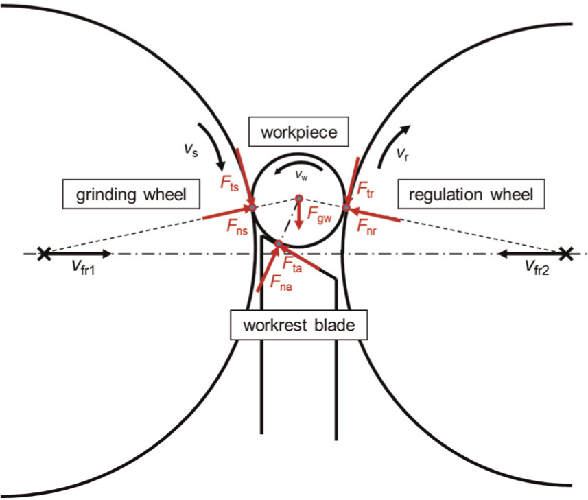
Force vectors and moments in the grinding gap.
Figure 2 shows the equilibrium of forces in the workrest blade and the geometric relationships. This shows that by means of the workrest blade angle β and the measured vertical force FyA, the calculation of the resulting force FA is possible. 10 This is necessary to comprehend the impact on the grinding process of the workrest blade angle β
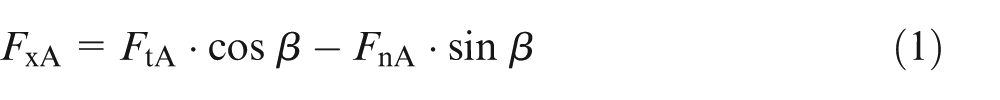
Force vectores at the work rest blade.
As part of the experimental investigations, the tangential force (FtS) was determined. Furthermore, the vertical force (FyA) was measured by means of a specially designed workrest blade (Figure 3). For this purpose, a divided workrest blade was constructed, in which two piezoelectric force sensors from the company Kistler (9132A slimline sensor) were installed. The integration of a triaxial force sensor was not possible due to the low grinding gap of 12 mm. The experimental setup is shown in Figure 4.
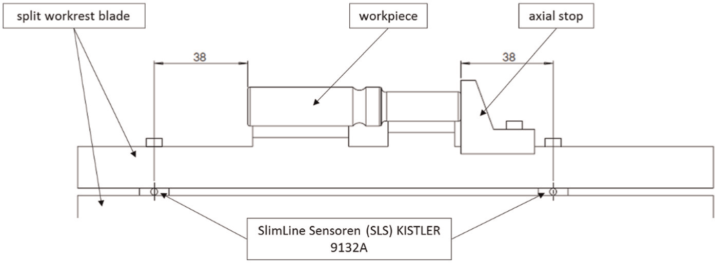
Schematic layout of the workrest blade with integrated force sensors.
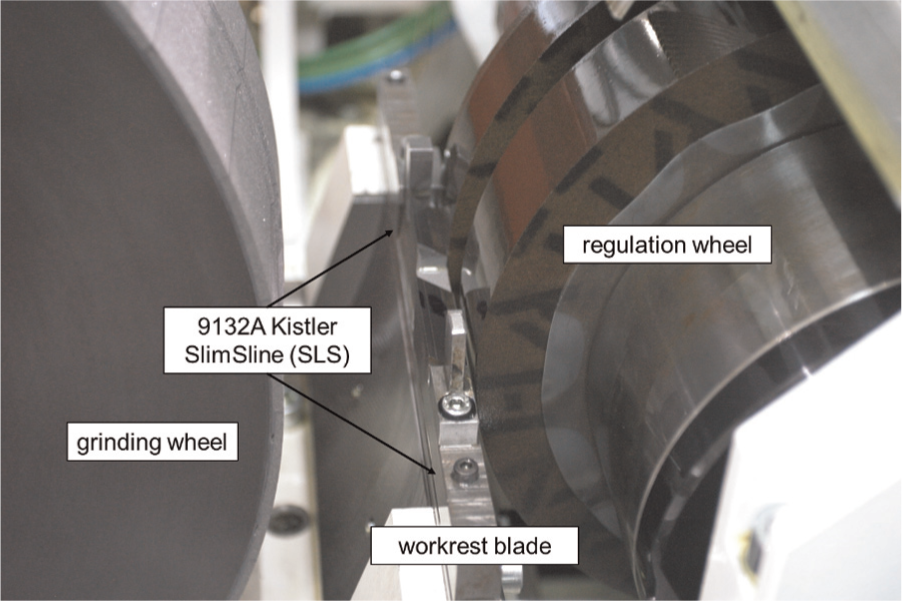
Workrest blade with integrated force sensors, grinding wheel and regulation wheel.
The sensors are integrated 20 mm below the contact surface of the workrest blade (Figure 3). This was done, on one hand, in order to minimise the error which may occur through the bending of the upper section and, on the other hand, to ensure the necessary stability in the grinding gap. 11 The sampling rate was set to 2000 Hz.
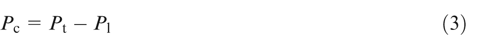
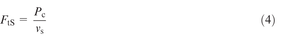
To determine the tangential force FtS, the total power Pt of the grinding spindle was recorded. The average power Pc can be determined by subtracting the idle load power Pl. By means of the grinding wheel speed vs, the tangential force FtS is calculated
Experimental procedure
During plunge-cut centreless grinding, the grinding process is divided into several stages: rough machining, semi-finishing, fine finishing and sparking-out (Figure 5). This is achieved by changing the radial displacement in the direction of the radial feed speed
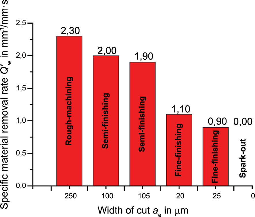
Multilevel process management.
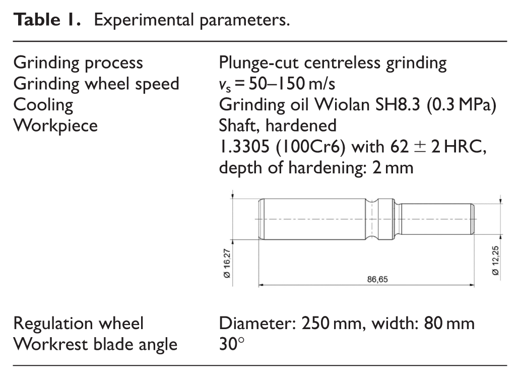
Experimental parameters.
As testing machine, a MIKROSA KRONOS S 250 (Figure 6) with a maximum spindle power of 15 kW was selected. Due to the use of a hybrid bearing system of the grinding spindle, a grinding wheel speed up to vs = 150 m/s can be achieved.
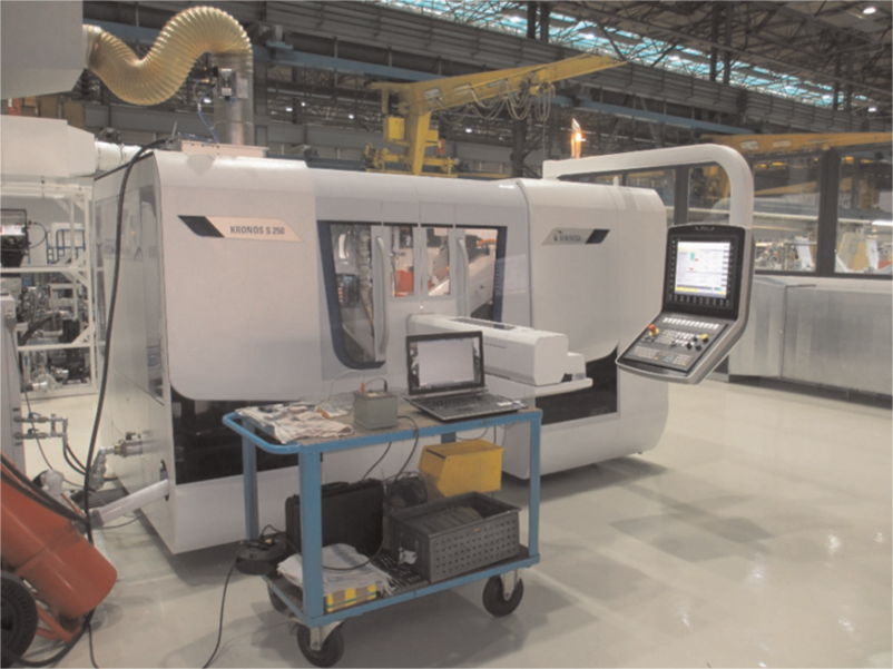
Test machine MIKROSA KRONOS S 250.
Grinding tools
Two different modifications of the grinding tools were applied, which were utilised up to their maximum allowable speed. More relevant information can be found in Table 2.
Modification of the tested tools.
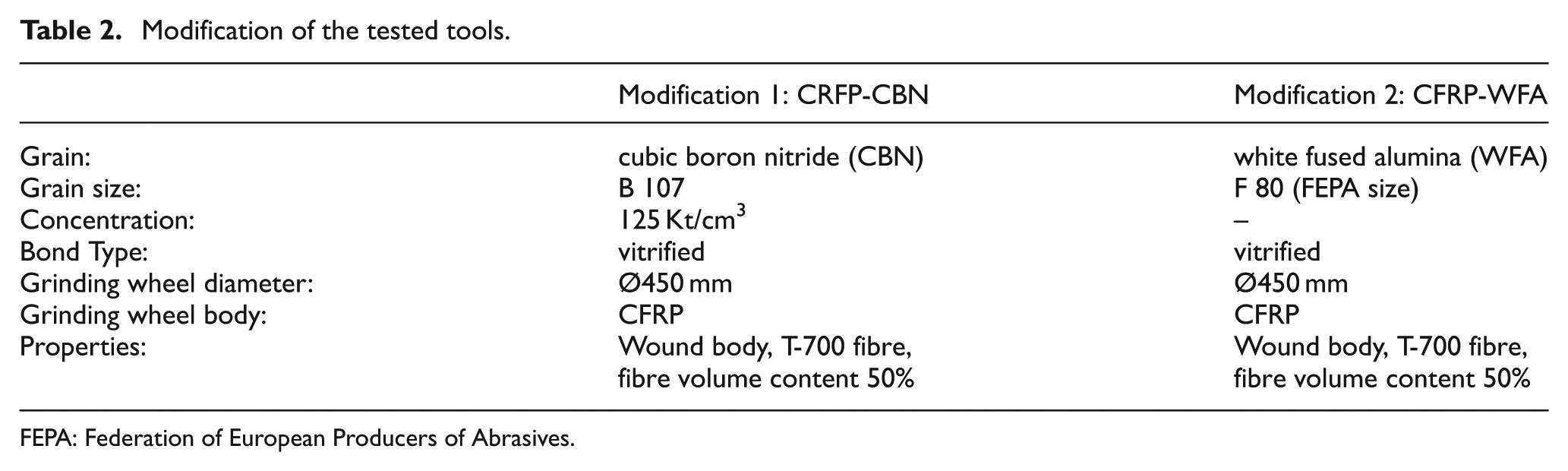
FEPA: Federation of European Producers of Abrasives
The segmented grinding wheel (Figure 7) has been newly developed for this investigation and is used up to a grinding wheel speed of vs = 150 m/s. The grinding wheel base body is a hybrid construction and made of CFRP and an inner ring of C45 steel (1.0503). The grinding wheel can optimally be mounted on the spindle and a high degree of concentricity can be ensured. The grinding wheel base body is a wound body in which the fibres are deposited circumferentially. The grinding wheel has a weight of 21.85 kg. This corresponds to approximately one-quarter of the weight of a grinding wheel base body made of steel. The choice of grain size and concentration was based on a predetermined average surface roughness (axial on the outer surface with Rz < 3 µm and Ra < 0.5 µm); thereby, a comparison of the different grinding wheel specification was possible.
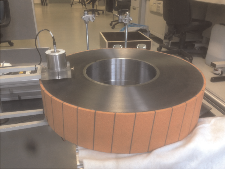
Grinding wheel with CFRP body (Modification 2, CFRP-WFA)
Results and discussion
Maximum tangential force Ftsmax on the grinding wheel
Figure 8 shows the maximum tangential force Ftsmax for the tested grinding tools, whereby the magnitudes of the observed force components decreased with increasing grinding wheel speed. At each test point, lower maximum tangential forces Ftsmax were measured for the CFRP-CBN grinding wheel (Modification 1) than for the CFRP-WFA grinding wheel (Modification 2). This indicates that the CFRP-WFA grinding wheel has an higher effective grinding wheel hardness compared to the CFRP-CBN grinding wheel.
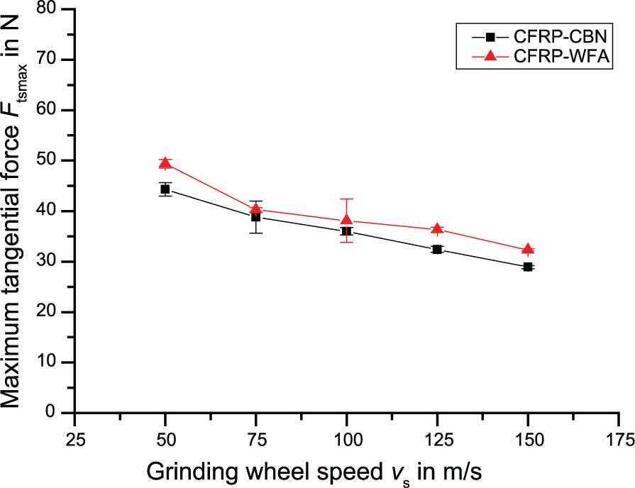
Maximum tangential force Ftsmax as a function of the grinding wheel speed vs.
The reduction of the maximum tangential forces with a grinding wheel speed between 50 and 150 m/s is about 30% for both modifications. The high grinding wheel speed results in an equivalent decline of the chip thickness and thus the loads on the grain. 3
Maximum vertical force FyAmax on the workrest blade
Similar to the results of the maximum tangential force Ftsmax, the maximum vertical forces FyAmax decreased significantly with an increasing grinding wheel speed (Figure 9). For the CFRP-CBN grinding wheel as well as for the CFRP-WFA grinding wheel, the maximum vertical forces for the full range of tested grinding wheel speeds reduced by more than 50%.
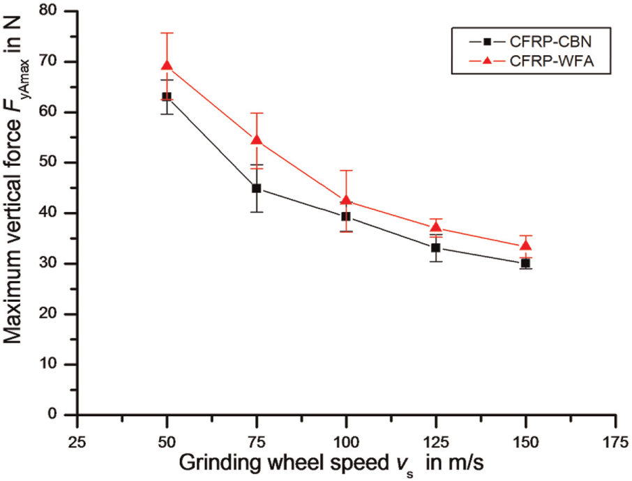
Maximum vertical force FyAmax as a function of the grinding wheel speed vs.
With increasing grinding wheel speed and therefore decreasing maximum vertical forces FyAmax, both the normal and the tangential components of the force FA were reduced.
Since the equivalent chip thickness is being reduced by increasing grinding wheel speed, the grain wear is reduced and the surface quality can be enhanced. 13
Force progression
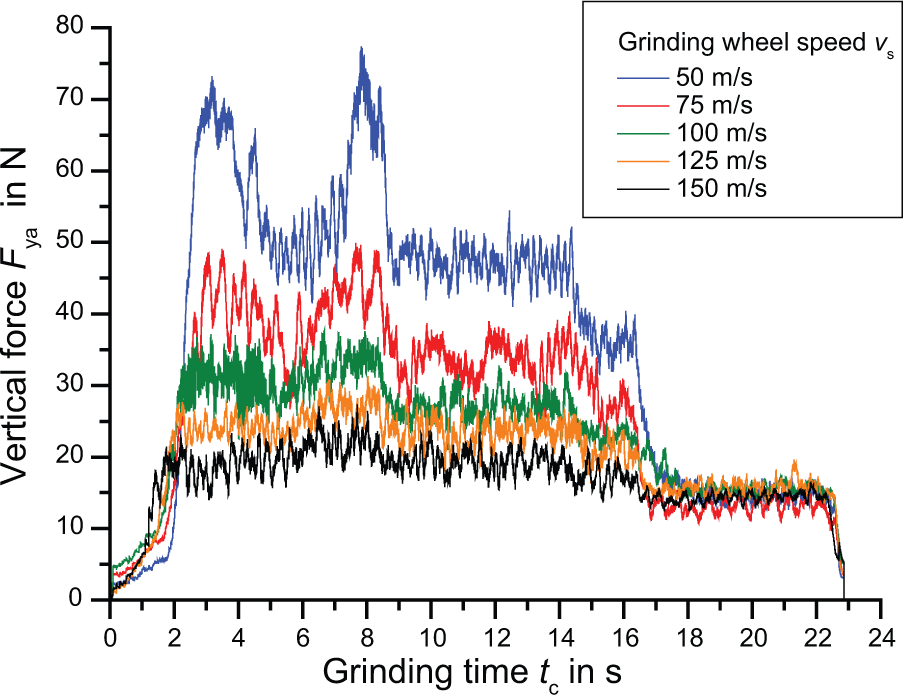
Detailed statements about the effects of forces can be achieved by the force progression of the grinding process. The average force progressions are calculated from four individual progressions.
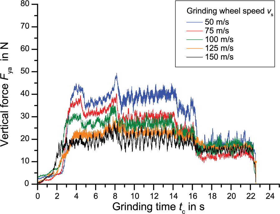
In Figures 10 and 11, the force progressions of the vertical force FyA are illustrated for the CFRP-WFA grinding wheel and CFRP-CBN grinding wheel, respectively.
Force progression of the vertical force FyA for CFRP-WFA.
Force progression of the vertical force FyA for CFRP-CBN.
The course of each graph shows several plateaus indicating the different process steps. For most process steps, the plateaus remain constant with little deviations.
However, this does not apply to the rough machining step. This is reasoned by the fact that the grinding wheel is in contact with the workpiece initially on the large diameter, then on the small diameter and, finally, on the bearing track. The grinding wheel only engages over the entire length of the shaft component during the first semi-finishing stage. The reason is that in order to ensure process stability, the tool has a larger profile section than the difference between the large and small shaft diameter on the test workpiece (about 200 µm).
The vertical forces FyA are significantly lower for the complete grinding process at a grinding wheel speed of 150 m/s compared to the tests at 50 m/s. Furthermore, it is apparent that the force differences between the process steps at 150 m/s can hardly be perceived. This constitutes an approximately uniform stress load. It is significant that the peak load at the beginning is less than the described maximum force at the end of rough machining. Furthermore, the dispersion of the maximum vertical force decreases with the increasing grinding wheel speed.
A uniform force profile with reduced dispersion lowers the risk of dynamic instability and decreases the formation of roundness errors and chatter marks. With regard to grain wear, equal loads should have a positive impact and reduce the risk of grain breaking.
Using the CFRP-CBN grinding wheel, fluctuations of the forces were detected at vs = 150 m/s. The reasons were slight differences in the workpiece edge zone by geometrical and material-specific tolerances of the test pieces and, therefore, slight changes in the grinding conditions. Another reason may be deteriorated contact conditions between the workpiece and the regulating wheel, due to slightly different coefficient of friction µr.
It is remarkable that for a grinding wheel speed of 150 m/s, the measured vertical forces are approximately equal for both grinding wheel modifications. At lower grinding wheel speeds, however, significantly lower forces for the CFRP-CBN grinding wheel are evident. This leads to the conclusion that even at high grinding wheel speeds, conventional abrasives have a good cutting ability.
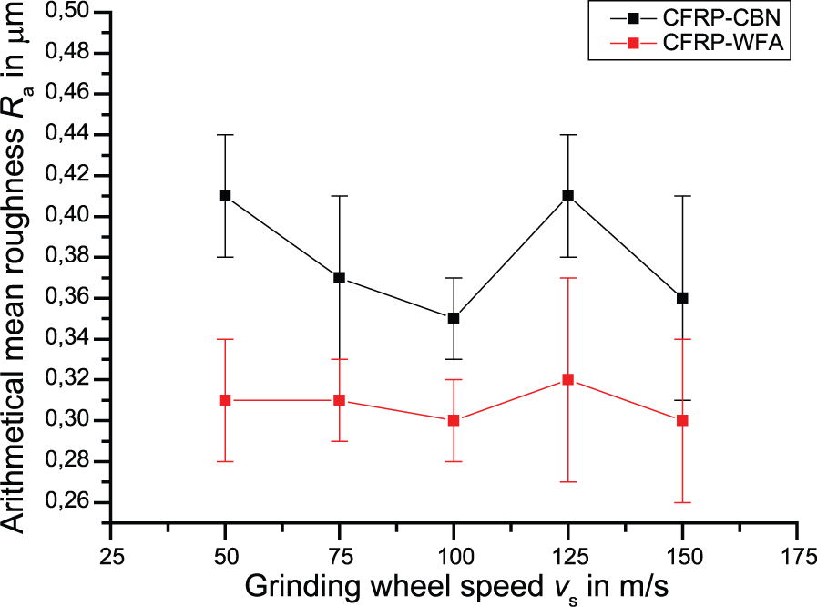
Surface quality roughness Ra and Rz
In Figures 12 and 13, the evaluation of the arithmetic mean roughness Ra and the averaged roughness height Rz are illustrated, respectively. With the increase of the grinding wheel speed, the arithmetical mean roughness Ra using both grinding wheel modifications can be regarded as constant. The predetermined quality restrictions of Rz < 3 µm and Ra < 0.5 µm can be adhered to all test points.
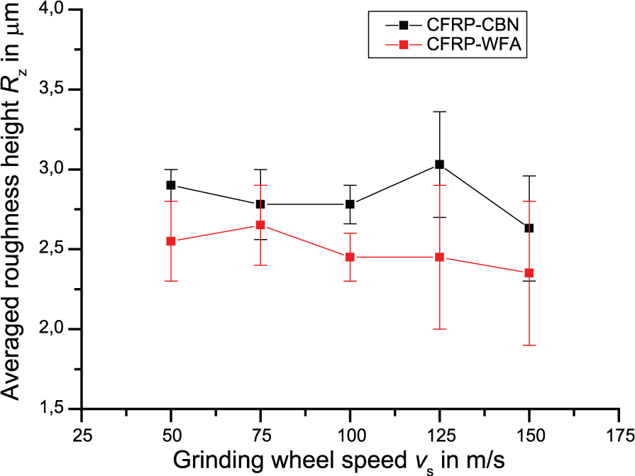
Averaged roughness height Rz as a function of the grinding wheel speed vs.
Arithmetical mean roughness Ra as a function of the grinding wheel speed vs.
It appears, however, that with an increase of the grinding wheel speed, the scattering of the roughness parameter rises. Several reasons are possible: process-induced vibrations can be triggered by a dynamic imbalance in the grinding wheel, higher temperatures have an impact on the contact zone or an insufficient coolant supply has increased the dispersion of the roughness.
This analysis shows furthermore that the grinding wheel specification in the form of grain type, grain size and concentration essentially determines the surface quality. An improvement in the surface quality is barely visible through the increase in the grinding wheel speed.
This result proves that a high degree of surface quality using high-speed plunge-cut centreless grinding can also be produced applying conventional abrasives. These results can be integrated into an intelligent system for the computer-based selection of grinding wheels regarding the grain as well as the body structure. 14
Summary
To realise the high grinding wheel speed, new grinding wheels have been developed, which have a CFRP grinding wheel base body with only one-quarter of the mass of a steel base body. The technical operational capability for grinding wheel speeds up to 150 m/s could be proven with these experiments through the use of the test machine MIKROSA KRONOS S 250. In order to measure the maximum vertical force FyAmax on the workrest blade, a new workrest blade with integrated force measuring sensors has been designed, and its applicability for these test parameters has also been substantiated.
In this study, a reduction of the maximum tangential force Ftsmax and the maximum vertical force FyAmax of more than 30% and 50% were measured for a WFA grain and a CBN grain by increasing the grinding wheel speed from 50 m/s up to 150 m/s, respectively.
A high grinding wheel speed (>120 m/s) generates uniform force progression, which has a positive impact on the grain wear and lowers the risk of grain break-out. As a result, conditioning cycles can be extended and non-productive times reduced.
In addition, this study shows that conventional abrasives, such as WFA grain, can be used in high-speed grinding. The tangential and vertical forces (FtS and FyA) decrease by the same amounts as a CBN grain and approach by rising grinding wheel speeds. This illustrates enormous potential in saving tooling costs, since conventional abrasives are multiple times cheaper than super abrasives.
The analysis of the surface quality showed that with the increase in the grinding wheel speed, the quality parameters Rz and Ra remain nearly constant. In addition, at each test point, the CFRP-WFA grinding wheel produces a lower roughness parameter on the workpiece compared to the CFRP-CBN grinding wheel, which further confirms the potential use of conventional abrasives.
Footnotes
Appendix 1
Acknowledgements
The authors acknowledge the United Grinding Group AG for the use of the testing machine MIKROSA KRONOS S 250 and the Hermes Schleifkörper GmbH for the grinding tools.
Declaration of conflicting interests
The author(s) declared no potential conflicts of interest with respect to the research, authorship and/or publication of this article.
Funding
The author(s) received no financial support for the research, authorship and/or publication of this article.