
Abstract
The ability to predict the critical depth for ductile-mode grinding of brittle materials is important to grinding process optimization and quality control. The traditional models for predicting the critical depth are mainly concerned with the material properties without considering the operation parameters. This article presents a new critical energy model for brittle–ductile transition by considering the strain rate effect brought by the grinding wheel speed and chip thickness. The experiments will be conducted through a high-speed diamond grinder on reaction-sintered silicon carbide materials under different grinding speed and chip thickness. Through detailed analysis of the strain rate effect on the dynamic fracture toughness, a new fracture toughness model will be established based on the Johnson–Holmquist material model (JH-2) and calibrated through experiments based on the indentation fracture mechanics. Then, the new critical model for brittle–ductile transition will be established by introducing the dynamic facture toughness model considering the wheel speed and chip thickness. According to scanning electron microscope observations, the results show that ductile-mode grinding can be obtained through a combination of higher grinding speed and smaller chip thickness. Moreover, the critical value for ductile grinding of brittle materials can be improved through the elevation of the grinding speed or reduction in the chip thickness.
Introduction
As typical brittle materials with high hardness, excellent wear resistance and extremely high-temperature strength, engineering ceramics are now being increasingly used in engineering applications such as bearing, valves and optical components.1,2 Grinding with diamond wheels3,4 is generally considered as the main processing method which can be expected to obtain a desired dimensional tolerance and surface integrity. However, machining of this ultra-hard ceramic material will inevitably cause microcracks 5 and subsurface damage 6 which will deteriorate surface quality. 7 In order to achieve crack-free and high-quality products without post-processing, ductile-regime machining was put forward for brittle materials. This kind of machining mode can generate the chips through a mode of plastic deformation rather than fracture and thus a higher accuracy of the machined surface. 8
In the last decades, ductile machining has been widely reported. In 1954, King and Tabor 9 observed the ductile-mode machining for the first time during frictional wear of rock salts. He found that although there were some cracks, there was still some plastic deformation involved. In the subsequent work, Lawn et al. 10 reported that there is a critical depth when indenting a hard material and the critical depth can define the transition from a failure characterized by plastic deformation to a failure characterized by fracture. Afterwards, Lawn and Marshall 11 proposed an empirical formula for the required lower bound of the critical load P and the resulting critical crack length C correlated with the fracture toughness and hardness of the substrate material. Blake and Scattergood 12 introduced the material removal energy to explain the ductile–brittle transition. Later on, Bifano et al. 13 presented a ductile–brittle transition model on the basis of the material removal energy, 12 where the ductile grinding can be achieved under a certain critical chip thickness value. This critical model is independent from the process parameters and only correlated with material mechanical properties. In the later works, the brittle–ductile transition models show more correlations with machining tools and process parameters. Venkatachalam et al. 14 proposed a fracture-toughness-based model to predict the ductile–brittle transitional undeformed chip thickness and analyzed different influence factors in end-turning of silicon wafer. Arif et al. 8 proposed a specific cutting-energy-based model to predict the ductile–brittle transition point in ultra-precision machining of brittle materials. The energy expended in brittle and ductile modes of machining is modeled as a function of work-material intrinsic properties, tool geometry and process parameters. A lot of simulations were undertaken to provide more theoretical support for ductile machining of brittle materials. A newly established molecular dynamics (MD) simulation 15 interpreted the origin of ductile response for silicon carbide (SiC), which is a combination of high-pressure phase transformation (HPPT) and dislocation activities, while dislocation plasticity plays a major role. For further investigation of ductile grinding of SiC, Liu et al. 15 established a dynamic fracture toughness model based on the Johnson–Holmquist material model 16 (JH-2) and then a series of MD simulations for single grit interaction with workpiece were conducted to conclude that the SiC workpiece will get toughened when the wheel speed increases. However, the above works about ductile machining are either in a relative lower machining speed or in micro-machining, which has its limitations to more extensive application. Moreover, the critical model for ductile machining did not fully consider the joint influence of machining speed and chip thickness.
The high-speed grinding (HSG) process was characterized by the elevated wheel velocity of above 60 m/s, which dramatically reduces the maximum chip thickness and thus a reduce of grinding forces. 17 In the past decades, HSG has been developed as a finishing process in order to avoid the grinding-induced damage layer on the ceramics. 18 In order to avoid brittle fracture in grinding of ceramics, the wheel velocities were increased, leading to an improvement in ground surface quality when grinding was conducted within the region where ductile flow was prevalent. 18 Kovach and Malkin 19 clearly demonstrated that HSG of advanced ceramics can result in an improved surface finish. Their results also showed a transition from a brittle fracture mode to a low damage ductile grinding mode could be achieved when the wheel speed elevated. Similar results were also reported in the HSG of silicon nitride. 20 Moreover, the increased wheel speed can greatly improve the depth of cut and feed rate to obtain a higher material removal rate while not deteriorating the ground surface integrity. 21 Through finite element method (FEM) simulation and experiments, Li et al. 22 show that the actual brittle–ductile transition point for SiC is larger than that derived from the quasi-static condition. However, insufficient practical investigation for ductile grinding of SiC is given in their work, a quantitative description needs to be further discussed.
In the HSG of brittle materials, the increase in the wheel velocity will definitely enhance the strain rate of material when the grinding wheel interacts with the workpiece. It has been reported that the increase in the strain rate will definitely affect the material mechanical properties, especially for fracture toughness. The fracture toughness of marble in high loading rate was investigated using a servo-hydraulic machine and a modified split Hopkinson pressure bar. 23 The results indicated that the increase of loading rate can lead to a substantial enhancement of the dynamic fracture toughness. The above results can also be concluded from the dynamic fracture toughness model established by Liu et al., 15 and the MD simulations for HSG of SiC in their work are fully discussed. Wu et al. 24 conducted the HSG experiments to investigate grinding temperature of SiC and concluded that the grinding temperature is generally between 150 °C and 400 °C. Huang and Zhu 25 investigated the high-temperature strength of SiC and proved that the the fracture toughness and flexural strength did not change when it is under 800 °C. Therefore, the effect of grinding temperature on ductile grinding will not be discussed in this article.
From the above literature review, it is clear that the grinding wheel speed and other operation parameters will have a great influence on the brittle–ductile transition of brittle material. However, the previous research for brittle–ductile transition did not fully investigate the effects brought by the grinding wheel speed and chip thickness. Therefore, this article is devoted to establish a new critical model for brittle–ductile transition by considering the strain rate effect brought by the grinding wheel speed and chip thickness. To achieve this, JH-2 model will be used to illustrate the strain rate effect on grinding process and then a previously established energy-based model will be revised by considering the dynamic fracture toughness. And this dynamic fracture toughness model will be established based on the JH-2 model and then calibrated on the basis of indentation fracture mechanics. Finally, the new critical energy model will be set up and a series of experiments will be conducted to verify the prediction accuracy.
Theoretical model for ductile grinding
Critical energy model of general criterion in ductile-regime grinding
Bifano et al. 13 established a chip thickness model by considering material removal energy, which is totally independent from the process parameters. It can be expressed as
where β is a constant which is determined by material properties. E, HV and K1C are the elastic modulus, the hardness and the mode-1 fracture toughness, respectively. According to a series of grinding experiments 13 on different brittle materials, the constant β is obtained and β = 0.15 for any brittle materials (less than 10% fracture surface). Based on equation (1), the critical value for SiC is about 0.06 µm (E = 415 GPa, HV = 23 GPa and K1C = 3.5 MPa m1/2), 22 which is too small and can only be achieved under a very low material removal rate. In ductile-regime grinding of brittle materials, Bifano 26 has shown that if the maximum undeformed chip thickness hcu of single abrasive grit is less than the critical depth of penetration dc, the grinding will be in the ductile regime. The maximum undeformed chip thickness is written as follows23,27
where Nd is the active grit number in unit area; ϕ is the semi-included angle of the active grit; ae is the depth of cut; Vw is the workpiece speed; Vs is the grinding wheel velocity; and de is the equivalent wheel diameter,
where dg is the equivalent spherical diameter of diamond grit, ω is the volume fraction of diamond in the grinding wheel and χ is the fraction of diamond particles that actively cutting in grinding. The grinding wheel used in this article has a density of 150, or in other words, volume fraction ω is 0.375. 32 The active grit are assumed that one-third of the total diamond particles are actively engaged in cutting, 33 or the value of χ is equal to 1/3.
Strain rate effect analysis based on JH-2 model
From the above description of the general criterion for ductile grinding, the critical value for SiC (0.06 µm) is relatively small, which means that a ductile grinding of this brittle material will only be conducted under either micro-grinding or extremely lower material removal rate. According to impact fracture mechanics and dynamic fracture toughness, Kalthoff 34 believed that the dynamic stress intensity factor cannot be determined by static stress intensity factor. The strain rate effect should be considered in the study of ductile grinding of brittle materials.
In study of the grinding mechanism, the JH-2 model has successfully been used in the simulation analysis and provided theoretical support for application of JH-2 model in grinding research. Based on the JH-2 model, Zhu et al. 35 and Yuan et al. 36 developed the finite element analysis on investigation of crack propagation and optimized the grinding parameters. When interacting with the workpiece, the abrasive grit will make intermittent processing, which is similar to the shock experiments in JH-2 model. Sun et al. 37 studied the grinding damages and transient stress in single grit simulation. It has been proved that the compression stress zone would be the main stress around the grits, which is very close to shock experiments in JH-2 model calibration. 38 Moreover, the strain rate in the JH-2 model has the range from quasi-static to more than 105/s (the experiments limit), 38 comparing with the simulation strain rate of 104–107. 39 For a further investigation of the experiments setup, the impact speed of JH-2 model was about 1000–5000 m/s on a specimen length of 80 mm. 38 While the grinding experiments was conducted between 20 and 140 m/s on a contact length of about 1–2 mm in this article. These indications all show good agreement on the application of JH-2 model in the study of grinding. Therefore, based on the above proof, the stress condition and strain rate in the grinding process was assumed to conform to the shock experiments in JH-2 model in this article. The JH-2 model is given below15,16
where σ is the material equivalent stress under the hydrostatic pressure P and strain rate
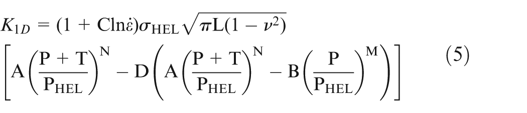
where K1D represents the dynamic fracture toughness, and L and ν are the length of the material crack and the Poisson’s ratio, respectively. It can be found from this model that the strain rate shows a positive logarithmic correlation with the dynamic fracture toughness K1D.
A new critical energy model for brittle–ductile transition considering the wheel speed and chip thickness
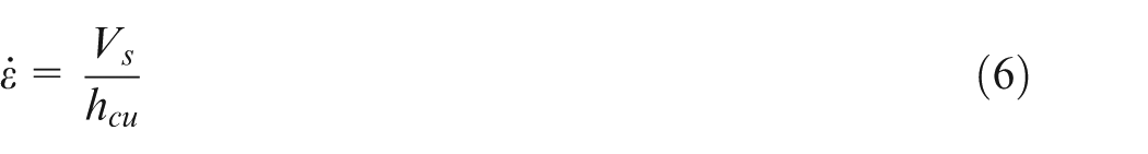
The strain rate is used to characterize the deformation velocity of the workpiece material; it is the derivative of the strain to the time. From equations (4) and (5), it can be found that the strain rate has a great influence on the material facture toughness. In the HSG, the increase in the grinding speed will lead to an increase in the strain rate substantially, and the strain rate can be calculated through the wheel speed divided by the maximum chip thickness hcu. It can be expressed as follows 40
Equation (5) has shown that the fracture toughness has a positive logarithmic correlation with the strain rate. Therefore, in order to analyze dynamic impact effect on the ductile grinding of brittle materials, the new critical model based on the model proposed by Bifano et al. 13 is given below
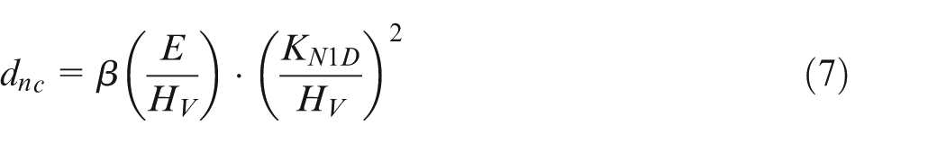
where dnc is the new critical model considering dynamic impact effect caused by the wheel speed. KN1D is the new dynamic fracture toughness brought by the strain rate. Based on formula (5), the new dynamic fracture toughness can be modeled as follows

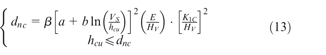
where K1C represents the static fracture toughness, which is the same with the one in formula (1) and can be applied in a low-speed grinding. a and b are the material constants and will be decided by experiments. Therefore, the new critical model for brittle–ductile transition of brittle materials considering the wheel speed and chip thickness can be obtained by adding equations (6) and (8) into (7)
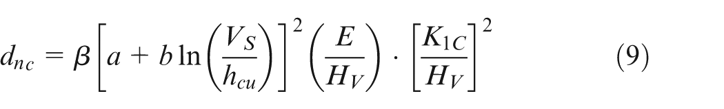
From this model, it is obvious that the critical value for brittle–ductile transition of brittle materials will be dependent on both the operation parameters and the material properties. The critical value will be elevated by introducing the grinding wheel speed and chip thickness, which means a higher removal rate can be achieved under ductile grinding.
Experiments
The detailed experimental conditions are given in Table 1. The experiments were performed on the MGKS1332/H CNC cylindrical grinding machine, which is capable of running up to 8000 r/min with a 400-mm wheel. The workpiece material used for this work is SiC with the elastic modulus of 350 GPa, hardness 23 GPa, static fracture toughness 3.5 MPa m1/2 and passion ratio of 0.16. The grinding wheel was trued using a diamond truer and dressed using an alumina stick of 200 mesh size for 30 s under coolant before experiments. The truing ratio for the grinding wheel is 0.8 under a wheel speed of 80 m/s, the depth of cut 2 µm and the transverse feed rate of 400 mm/min.
Experimental conditions.
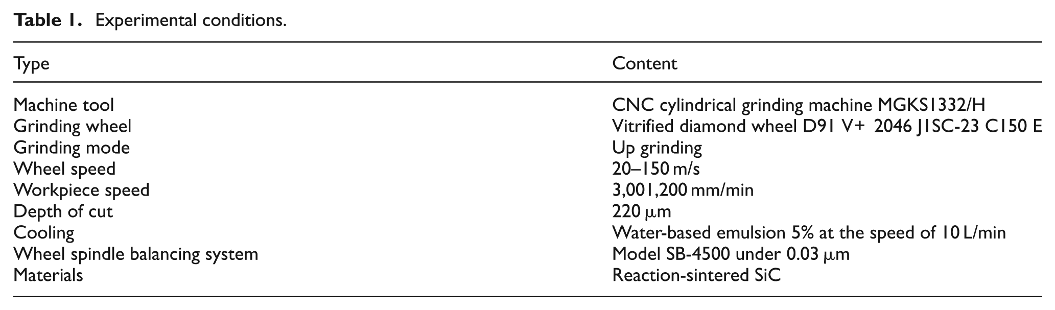
Figure 1 gives the detailed experiment layout. The material specimen in the top-right corner has a diameter of 60 mm and width of 20 mm. The workpiece was cut into two pieces. And the smaller part will be used to examine the ground surface and subsurface fracture crack size by an environment scanning electron microscope (ESEM) QUANTA 250 from Czech. A bonded interface sectioning technique 41 was adopted to examine the grinding-induced subsurface damage. Two parts of the material specimen were first polished and then bonded together using a cyanoacrylate adhesive. In order to minimize edge chipping and achieve a thin adhesive layer joint, clamping pressure was applied during bonding. The grinding direction was perpendicular to the bonded interface. After grinding, the bonded specimens were subsequently separated through heating on a hot plate to soften the bonding adhesive. Before the scanning electron microscope (SEM) observation, the ground specimens were cleaned with acetone in an ultrasonic bath pool for at least 20 min, and then gold coated. The grinding force detecting device is a three-direction force transducer (Kistler 9347C) mounted in the tailstock. The transducer is collected to a charge amplifier, and then the collected signal is sent to the data acquisition system LMS.
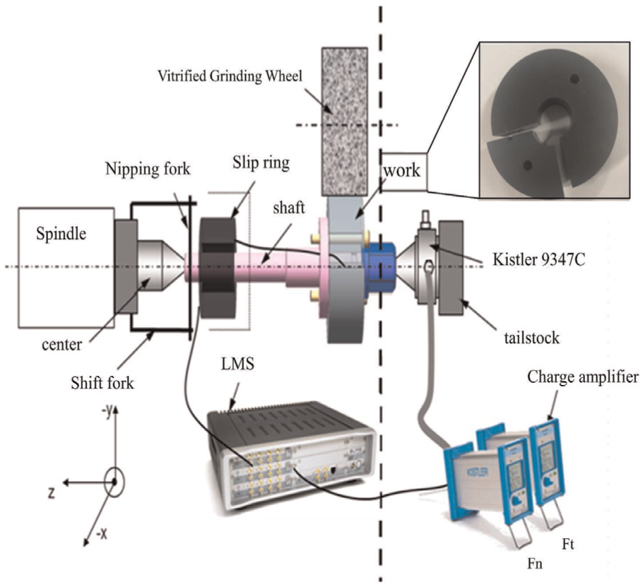
Experiments schematic.
Results and discussions
Determination of material constants a and b
Lawn and Evans 42 proposed a fracture mechanics model, which can provide a quantitative analysis of the crack system in elastic/plastic indentation. The model gives a clear description of the correlation between the load P and crack size Cr, and can be given as follows42,43
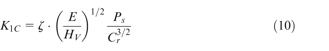
where ζ is a constant related to the material property, taken to be 0.01643,44 based on experiments, and Cr is the crack size. From the indentation fracture mechanics42–44 and formula (10), it can be found that the fracture toughness is positive to the relation
In grinding processes, when the abrasive grit interacts with the workpiece materials, the grinding forces will be generated. In order to quantitatively analyze material removal mechanism and operation parameters’ effects on the workpiece material’s performance, the average tangential and normal force for a single grit are given by calculating the ratio of grinding forces and active grits, the following are the given equations
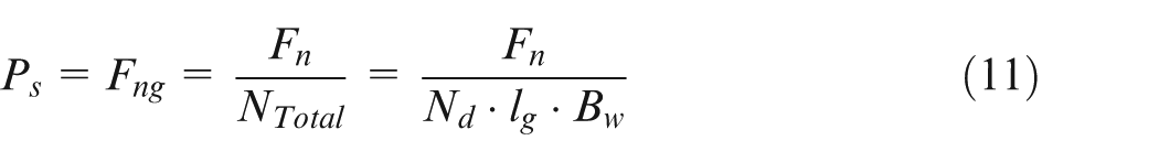
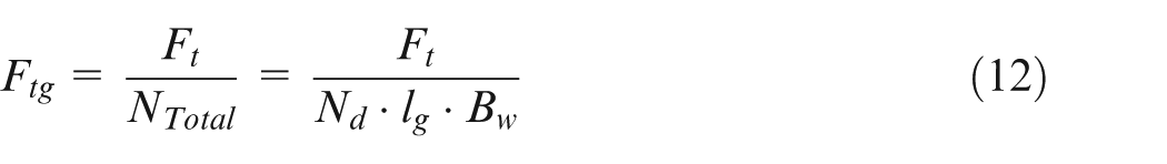
where Fng and Ftg represent the average normal and tangential force of a single grit, respectively; Fn and Ft are the whole normal and tangential grinding force from experiments, respectively; NTotal is the active grits number in whole contact area; lg is the contact arc length, written as
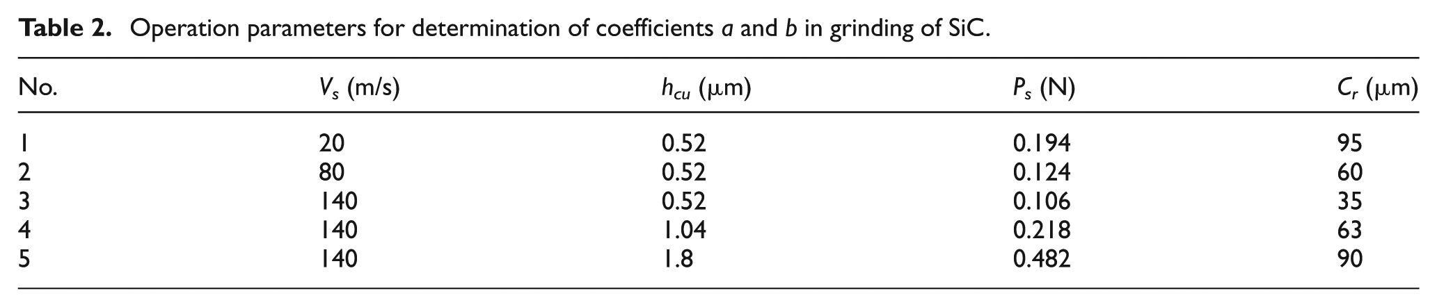
The crack size Cr was determined by the SEM picture illustrated in Figure 2. It is a typical quantitative characterization method for the subsurface damage depth caused by the normal force. In order to determine the coefficients a and b in grinding of SiC, a series of experiments are listed in Table 2. The resulted load and crack size are also given in this Table. Therefore, by combining formulas (10) and (8), the constants a and b can be obtained through the experimental data in Table 1. a and b are −1.64 and 0.675, respectively.
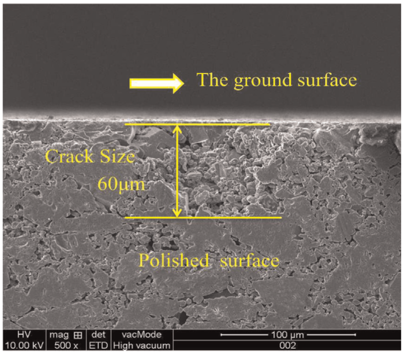
SEM for subsurface damage quantitative characterization.
Operation parameters for determination of coefficients a and b in grinding of SiC.
Model validation
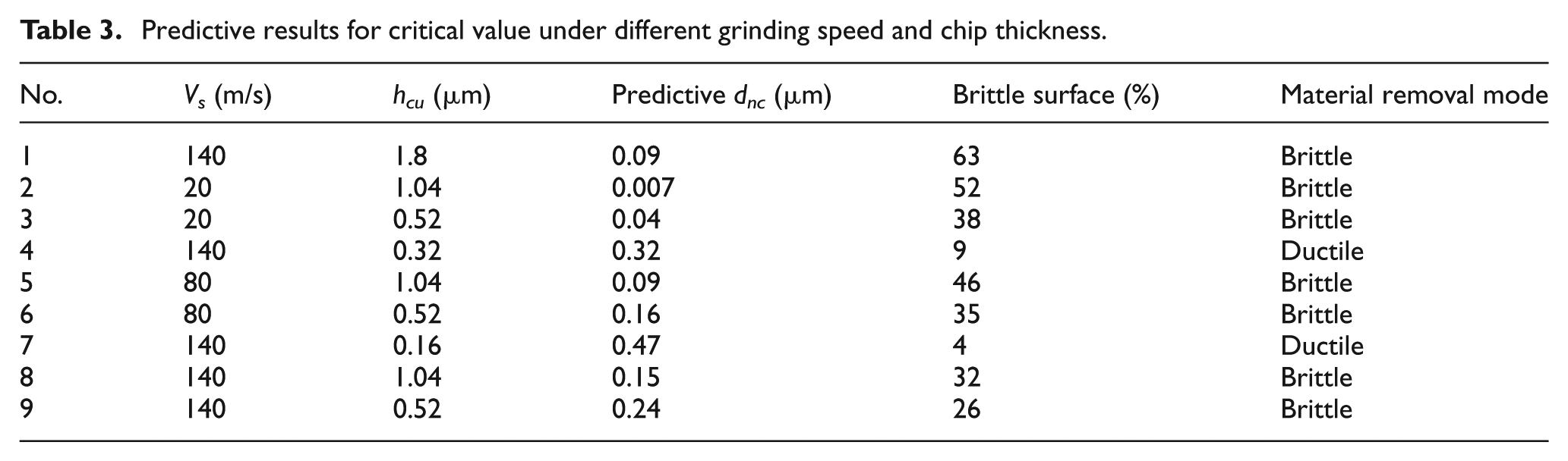
In order to validate the new critical model established in formula (9), a series of grinding experiments are conducted and the detailed process parameters are listed in Table 3. The new predictive results for ductile grinding of SiC (under 10% fracture surface 13 ) are also given in this table. The SEM pictures for ground surface under these operation conditions are given in Figure 3. From the SEM ground surface in Figure 3, it can be found that the ground surface is characterized by both ductile flow and fracture cracks for the irregular distribution of abrasive grits and machining process. The ductile ground surface is characterized by scratching groove and tiny burrs compared with more concave pits and coarse surface in the brittle ground surface. A grid counting technique 13 was devised to quantify the percentage of brittle surface in the whole surface. The results are also presented in Table 3.
Predictive results for critical value under different grinding speed and chip thickness.
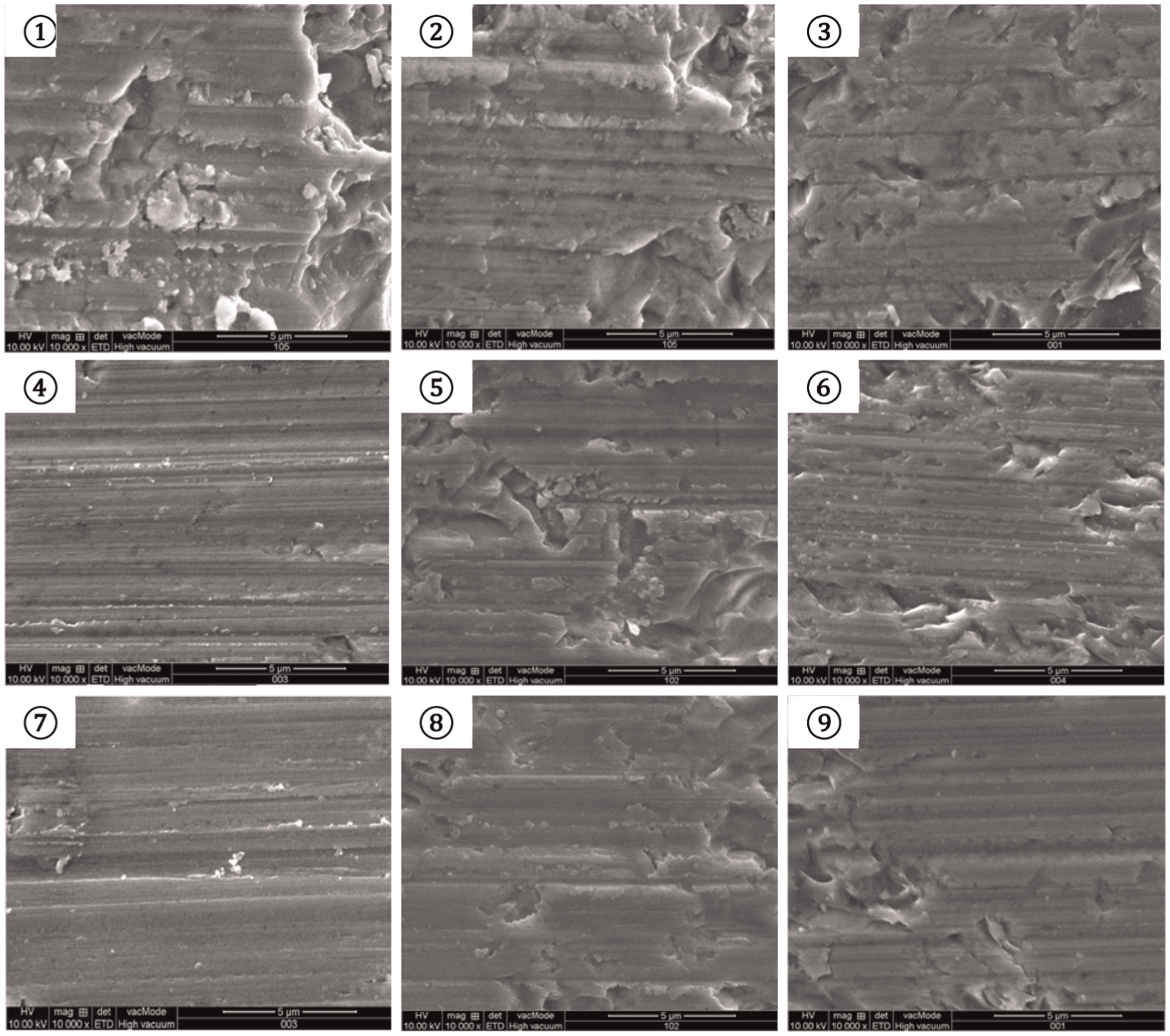
Ground surface SEM pictures under different wheel speed and chip thickness.
It has been proved that the ductile grinding can be achieved only when the chip thickness hcu is smaller than the critical value dnc. 26 The similar conclusion can also be drawn in Table 3. In this table, when the chip thickness hcu is higher than the predicted critical value dnc for brittle–ductile transition point, the ground surfaces have more than 10% brittle surface, which is defined as the brittle grinding. However, when the chip thickness hcu is equal or smaller than the predicted critical value dnc, the ground surfaces have a brittle surface below 10%, which is defined as the ductile grinding. It can be found from Table 3 that the chip thickness hcu for No. 4 has an equal value with the predicted value, resulting in a brittle surface lower than 10% in the fourth SEM picture in Figure 3. However, if the chip thickness hcu is much smaller than the predicted value, a more ductile ground surface can be obtained as shown in the seventh SEM picture in Figure 3. In Figure 3, it can also be found from the two right columns that the increase in the wheel speed under a constant chip thickness will lead to a better ductile surface, which means that the material is more inclined to ductile flow under a higher wheel speed. 19
From the above analysis, the new critical energy model for brittle–ductile transition considering the grinding wheel speed and chip thickness effects can be expressed in formula (13). a and b are the material constants
Discussions
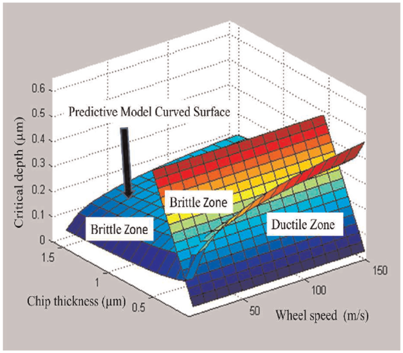
For SiC, the three-dimensional (3D) description for the new critical energy model in formula (13) is plotted in Figure 4. In this figure, the curved surface is the critical value for the predictive model, while the plane is the criterion that the chip thickness is equal or below to the critical value. It is obvious that the increase in the wheel speed will lead to an increase in the critical value, which is opposite to the chip thickness. Moreover, the ductile zone is under the predictive model curved surface when the chip thickness hcu is equal or smaller than the critical value, and it is indicated in the outward part of the space intersection between the two surfaces. The remains are the zone that cannot achieve ductile grinding of SiC.
3D description for the critical model of SiC.
Based on the 3D description in Figure 4 and the ground surface in Figure 3, it can be concluded that the critical value for ductile grinding of SiC can be improved by either elevation of the grinding wheel speed or the reduction in chip thickness. However, the increase in the grinding speed will not only help to remove materials in ductile model but also increase the material removal volume and greatly improve the machining efficiency. However, the reduction in the chip thickness will also help to increase the critical value for ductile grinding yet a reduction in the material removal volume. Therefore, in order to achieve a good surface finishing, application of HSG would be more efficient than conventional speed grinding under a small grinding depth.
Conclusion
Machining of hard and brittle materials will inevitably cause microcracks and subsurface damage, and it is always characterized by a complex removal mechanism of both ductile and brittle mode removal. This article proposed a new critical energy model for ductile grinding considering the grinding wheel speed and chip thickness effects. From this model, it has been proved that the critical value for brittle–ductile transition of brittle materials will not only be dependent on the materials properties but also the wheel speed and chip thickness. Moreover, the critical value varies under different operation conditions and can be elevated by introducing the grinding wheel speed and chip thickness, which means a higher removal rate can be achieved under ductile grinding. It can also be concluded from this new model that the increase in the wheel speed will lead to an increase of the critical value, while the chip thickness will lead to a negative drop in the critical value.
Footnotes
Acknowledgements
The authors wish to record their gratitude to their generous supports.
Declaration of conflicting interests
The author(s) declared no potential conflicts of interest with respect to the research, authorship and/or publication of this article.
Funding
This work is supported in part by the National High Technology Research and Development Program of China (2012AA041309), Innovation Funds of Donghua University (CUSF-DH-D-2015100) and Morris M. Bryan Jr Professorship for Advanced Manufacturing Systems.
Informed consent
Additional informed consent was obtained from all individual participants for whom identifying information is included in this article.
Research involving human participants and/or animals
This article does not contain any studies with human participants or animals performed by any of the authors.