
Abstract
Composites are cutting edge engineering materials for modern high-technology products. Their heterogeneous structure entails processing defects uncommon with metallic parts. Drilling is a crucial manufacturing process to facilitate fastening and assembly of composite components. High-speed drilling especially is a promising technique to increase the productivity as well as the quality of the drilled hole. The severity of delamination damage around the drilled hole is a critical factor in the error-free performance of these parts in service. A new method to characterize the delamination induced by drilling with a comprehensive assessment factor called effective equivalent delamination factor is developed to overcome the limitations of other measures being used hitherto. The capability and appropriateness of effective equivalent delamination factor as a delamination assessment factor are verified from experimental results.
Keywords
Introduction
Composite materials, due to their superior physical and mechanical properties, are progressively replacing many metals and metal alloys traditionally used for fabrication of structural parts in various industries. Common examples of composite laminates used in industries are carbon fibre–reinforced polymer (CFRP) composite laminates, glass fibre–reinforced polymer (GFRP) composite laminates, and fibre–metal laminates (FMLs). The application areas of fibre-reinforced composites include defence, transportation, and power generation sectors.1–3 Special characteristics of these materials make them difficult to machine as compared to other homogeneous materials. 4 Drilling is a very common secondary machining operation for facilitating assembly of parts made of fibre-reinforced materials. Defect-free drilling is crucial since drilling is a final operation as no reaming is usually carried out on composites. 5
Lachaud et al. 6 classify the drilling defects on composite materials into four categories: peel-up delamination, push-out delamination, geometric defects, and thermal damages. Delamination is a major damage encountered in drilling. 7 Rejection rates of up to 60% are reported in case of aircraft assembly work as a result of such defects. 8 Delamination commonly occurs at both the entry (peel-up) and the exit (push-down) planes of the work piece. The mechanisms of these are presented elsewhere.9,10
The size of the delamination zone has been shown to be related to the thrust force developed during the drilling process, and it is believed that there is a ‘critical thrust force’ below which no damage occurs. Zhang et al. 11 presented a mathematical model for predicting critical thrust forces in drilling composite laminates. Hocheng and Tsao 12 have found that the core drill provides a higher critical thrust force than the twist drill for delamination when drilling composite laminates. Cadorin and Zitoune 13 also confirm that core drills are preferable to twist drills for drilling composite laminates. The review paper on ‘Recent advances in twist drill design for composite machining – a critical review’ by Ismail et al. 14 suggests that the use of polycrystalline diamond, carbide, and high-speed steel tooling materials for developing a twist drill can minimize the delamination of reinforced composites with minimum tool wear and high-quality surface. Recent works of Feito et al. 15 present that high productivity with minimum delamination is possible in drilling of woven and tape CFRPs using a reamer drill.
Different delamination factors, as the measure of the damage, are used by various researchers. In the next section, delamination measurement methods are listed. Thereafter, the authors discuss the different delamination factors and then propose a comprehensive delamination factor.
Assessment of delamination
Many studies by various researchers have described different methods to obtain the shape and size of delamination of composites, which include X-ray,16–19 optical microscope,19–24 ultrasonic C-scan,18,19,25,26 acoustic emissions, 27 shadow moiré laser–based imaging technique, 28 digital photography,2,29 and digital radiography. 30 Silva et al. 31 used image processing methodology with predetermined optimal threshold value to quantify the delamination in CFRP composites. Recently, Hong et al. 32 presented ultrasonic signal analysis according to laser ultrasound generation position for the detection of delamination in composites. Ranjit et al. 33 presented a quantitative analysis of artificially created defects in glass fibre–reinforced plastic plate using lock-in infrared thermography. The thermographic method could detect the size, shape, and depth of the delamination. Maghsoodi and Ohadi 34 employed the Lamb wave method to detect damage in FMLs. They could successfully detect the delamination between fibre–epoxy and metal. Wang et al. 35 could predict the delamination with a mathematical model developed using shell theory. In this model, they assumed the delaminated area as round, and its diameter is used as Dmax in the formula of conventional delamination factor described in the next paragraph, for prediction.
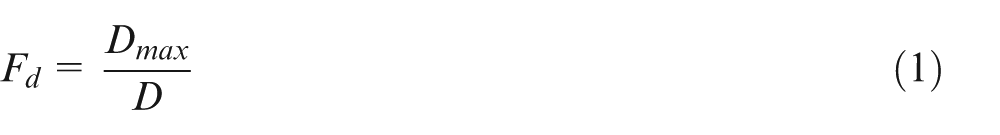
A measure of the delamination damage caused by drilling of laminated composites, called delamination factor (Fd), is proposed by Chen. 16 It is defined as the ratio of the maximum diameter of delamination (Dmax) to the nominal diameter of drilled hole (D). The formula is given in equation (1)
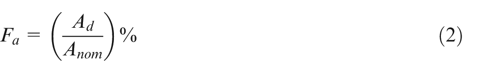
Faraz et al. 36 point out that Fd may give a high value of delamination since a few fibres delaminating can give a large radius with little delamination of the hole periphery. To overcome this, they propose a two-dimensional delamination factor (Fa), as given in equation (2)
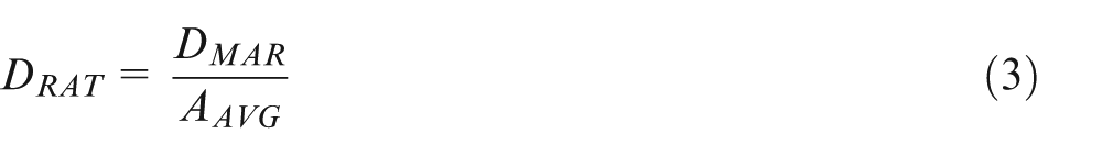
Mehta et al. 37 suggest a different measure called the damage ratio, DRAT. It is defined as the ratio of the damaged area at hole periphery, DMAR, to nominal area of drilled hole, AAVG, and it is calculated according to equation (3)
The delamination factor (Fd) does not consider the area of delamination as Dmax indicates just the crack length. The two-dimensional delamination factor methods
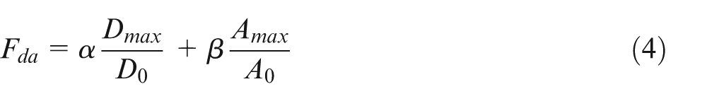
where α and
On substituting these values in equation (4), equation (5) is obtained
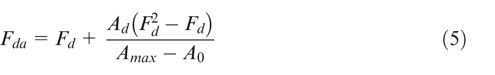
The adjusted delamination factor is superior to the previously mentioned factors in assessing the delamination. However, it tends to give a larger factor value than the others due to its additive formula. Therefore, another measure called the equivalent delamination factor (Fed) is proposed by Tsao et al., 26 as a measure of delamination. It is calculated by equation (6)
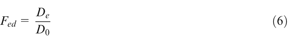
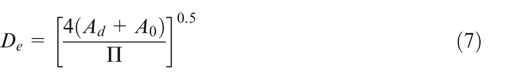
De is the equivalent diameter as calculated by equation (7)
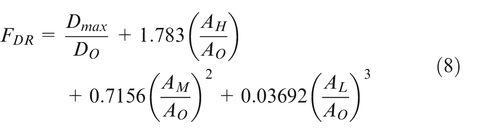
Nagarajan et al.
2
propose another measure called refined delamination factor (FDR). To calculate this, first the total damage area is divided into three zones, namely, heavy damage area (AH), medium damage area (AM), and low damage area (AL). They use Buckingham’s
Durão et al. 38 consider the shape of the damaged area to calculate the delamination factor. The shape’s circularity (i.e. the shape’s compactness compared to a circle of equal perimeter) is found out using equation (9)
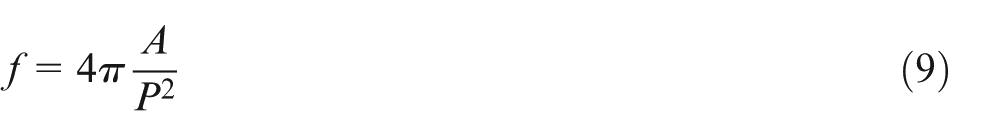
where A is the area of damage and P is its perimeter length. When the damage pattern resembles a circle, the circularity will be nearly 1. As the value approaches 0, the damage pattern becomes an elongated polygon. This method focuses on the shape of damaged area. But they are unable to establish a correlation between shape circularity and damage extension.
Silva
39
proposes a measure for the delamination damage caused by drilling, called the minimum delamination factor
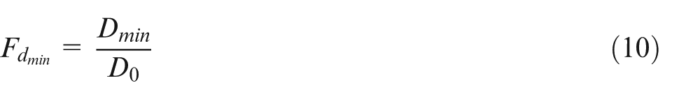
The value of
Detailed discussion on assessment of delamination in composite materials is presented by Babu et al. 40 in a review paper.
Proposed delamination factor
The conventional delamination factor does not take the damaged area into consideration. The two-dimensional delamination factors consider only damaged area neglecting the severity of cracks. Adjusted delamination factor appears to be a better approach than earlier mentioned methods as it takes into account both the maximum crack length and damaged area. This method differentiates delamination damage for the cases shown in Figure 1(a) and (c), and Fda values will be quite different for the two cases. But it may still be inaccurate in the assessment of the damage as can be explained with reference to Figure 1(b). Figure 1(b) consists of very fine cracks which may constitute very negligible area. Therefore, the delamination factors for Figure 1(a) and (b) can show almost the same value of Fda. But Figure 1(b) specimen will be prone to failure at a lower load application than Figure 1(a) specimen due to its more severe damage with a large number of fine cracks.
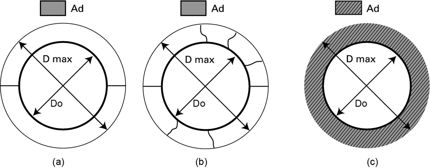
Diagram of the delamination damage: (a) fine crack with minimal delamination area, (b) more number of fine cracks, and (c) maximal delamination area (uniform damage in the vicinity of drilled area).
The effective delamination factor (Fed) and the minimum delamination factor
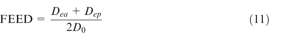
Therefore, in this study, a new approach is proposed to characterize the delamination with a factor called the effective equivalent delamination factor (FEED). It is calculated using equation (11), which gives equal weightage to the crack length and damage area, considering that both the factors have equal influence on the performance of the product. The scheme of FEED is illustrated in Figure 2
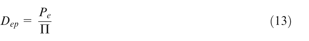
where
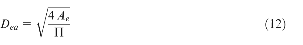
where
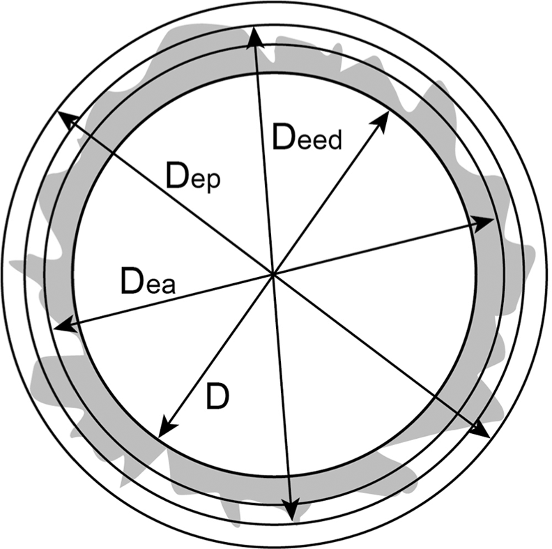
Scheme of the FEED in the delamination due to drilling the composite material.
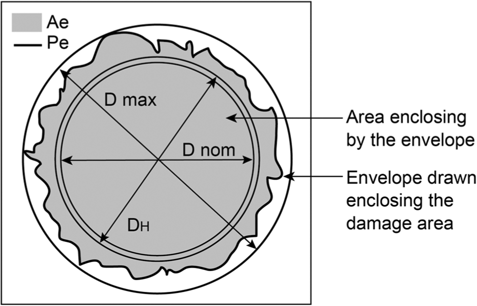
Scheme of Ae and Pe of the delamination damage due to drilling the composite material.
where Dea reflects area of delamination damage, and Dep reflects the crack lengths in the delamination; therefore, Dep will be always larger than Dea and D0. Average of Dea and Dep will normalize the delamination factor. A larger Dep reflects longer and more number of cracks, where the material is more prone to fail.
For a uniform damage as shown schematically in Figure 4, the conventional delamination factor, the equivalent delamination factor, and the FEED will all have the same value.
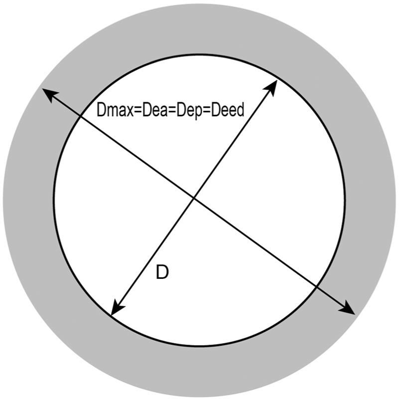
Scheme of the uniform damage representing where Fd, Fed, and FEED are equal.
This proposed method is a balanced delamination measure as it takes into consideration, in addition to the damaged area considered in the equivalent delamination factor Fed proposed by Tsao et al., 26 its perimeter too while assessing the delamination, thereby bringing in the effect of cracks in the damage. Another difference in the proposed method is to consider the area of the envelope of damaged zone, Ae, which may or may not be equal to the sum of Ad and A0, depending on the variation of actual hole diameter from its nominal diameter. A0 is the nominal area of the drilled hole and is calculated using the diameter of the drill bit, and Ad is the delaminated area in the vicinity of drilled hole. The sum of Ad and A0 is equal to Ae for the drilling conditions where the diameter of the drilled hole is equal to the nominal diameter of the drill. But at very high spindle speeds and low feed rates, the variation between diameter of the drilled hole and diameter of drill bit can be large. High spindle speeds and low feed rates cause frictional heating, making the cutting temperature to go up. 41 In the work of Rawat and Attia, 42 hole diameter error up to +6% is observed when drilling at a low feed rate of 20 μm/rev and a high spindle speed of 15,000 r/min but at lower spindle speeds the hole diameter error is much less. The delamination factor models, except Fed, include the increase in diameter of the hole in the delamination measure.
The proposed method uses area enclosed by the envelope of damaged zone and converts it into a circle to determine the equivalent diameter Dea. In addition, it considers the total crack length using the perimeter length of the damage to arrive at its equivalent diameter Dep. Using both these in the calculation of the delamination factor, the proposed method provides a balanced measure having the merits of both Fda and Fed.
Experimental procedure
Specimens of glass fibre–reinforced composite material were drilled in this investigation. The laminates composed of 13 layers are laid-up in the symmetrical form [0, 90]. The fibres were unidirectional (UD) E-glass. The applied resin was of grade L-12 with K-5 hardener. The thickness of the laminate was 3 mm. Drilling experiments were carried out on a MAKINO S33 vertical machining centre. Two-flute, 4- and 5-mm-diameter coated carbide (K20) drills with 30° spiral angle and 118° point angle were used for the trials. Flute length and total length of 5-mm drill were 52 and 86 mm, respectively, and those of 4-mm drill were 44 and 76 mm, respectively. Dimensions of the drill bit conformed to the DIN 338/IS 5101 standards. Process parameters chosen for experiments are shown in Table 1. All the trials were conducted without the use of a coolant. The delamination was measured by flat-bed scanner technique. For this, the specimen was placed directly on the glass plate of the scanner. The drilled holes were scanned at a resolution of 1200 PPI and saved as a bitmap image. The scanned images were imported into the image processing software ‘ImageJ’. The colour images were converted into a binary file. The threshold value for binary conversion was set by comparing the histogram of array values of delaminated zone with that of the undamaged area. A coordinate measuring machine (CMM) with 1-mm-diameter probe was used to determine the actual diameter of the drilled hole.
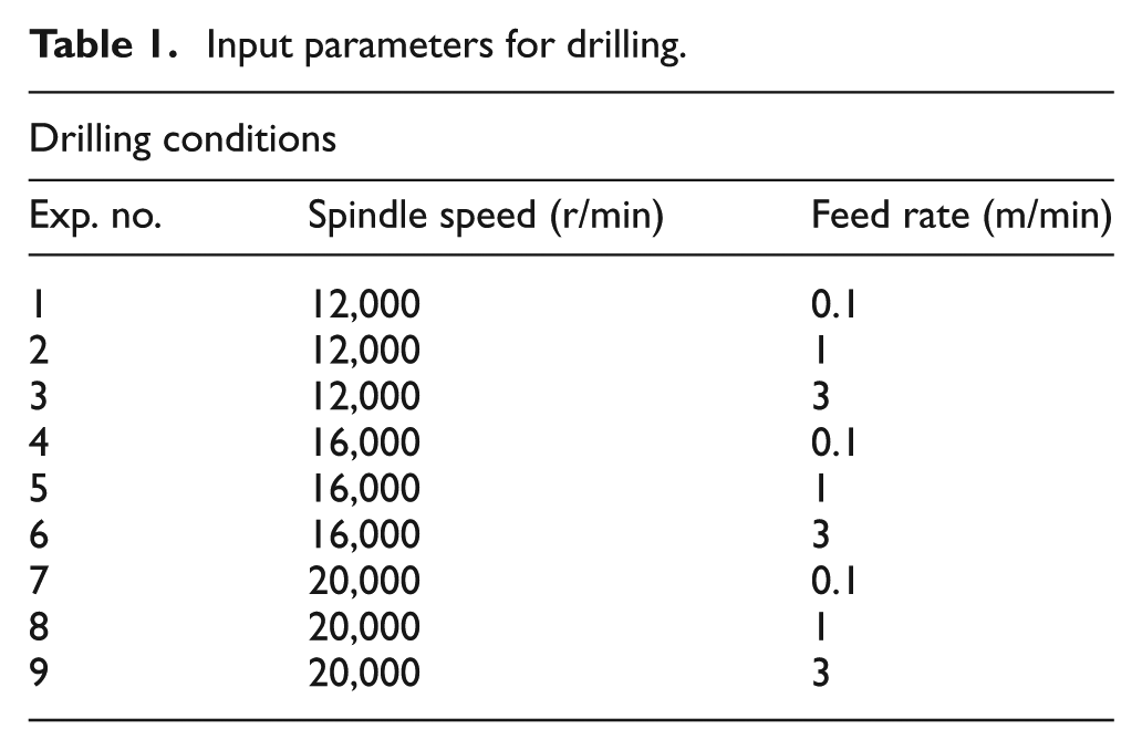
Input parameters for drilling.
Results and discussion
To evaluate the proposed measure of delamination, a comprehensive analysis is carried out by comparing it with the existing delamination factors. In the analysis, the existing factors considered are the equivalent delamination factor, adjusted delamination factor, and conventional delamination factor, being the more frequently used or better ones among the factors in use. Tables 2–5 show the experimental results of various delamination factor models obtained under chosen process parameters listed in Table 1. These results are charted out graphically in Figures 5–8. This section is subdivided into two: first, on the influence of process parameters on delamination and second, a comparison of delamination factor models.
Experimental results of exit delamination of various delamination models under selected drilling conditions for 5-mm drilled holes.
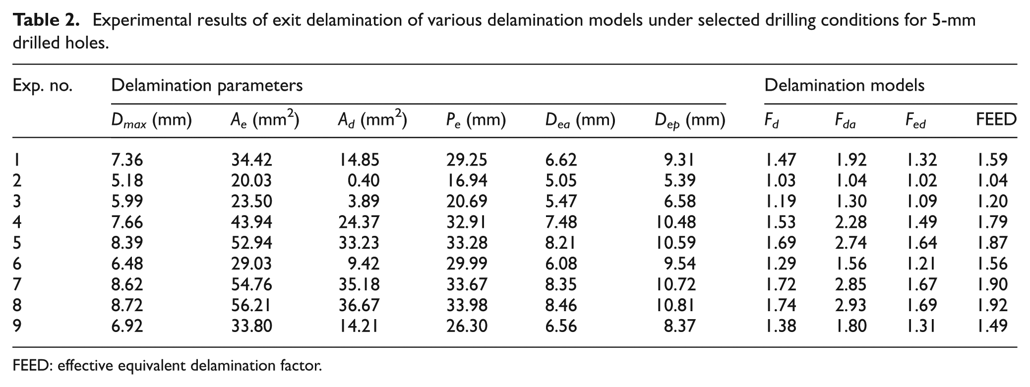
FEED: effective equivalent delamination factor.
Experimental results of entry delamination of various delamination models under selected drilling conditions for 5-mm drilled holes.
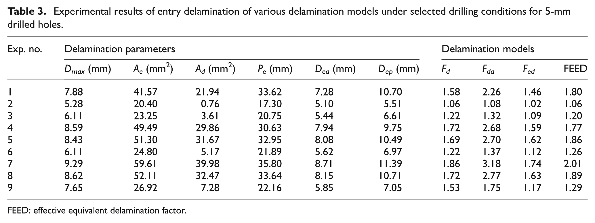
FEED: effective equivalent delamination factor.
Experimental results of exit delamination of various delamination models under selected drilling conditions for 4-mm drilled holes.
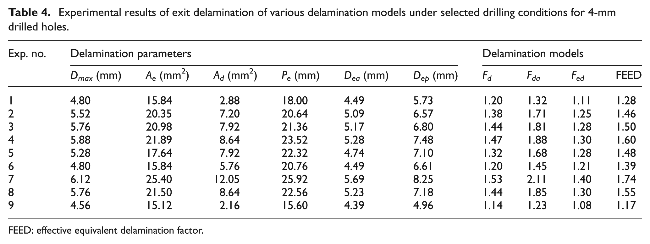
FEED: effective equivalent delamination factor.
Experimental results of entry delamination of various delamination models under selected drilling conditions for 4-mm drilled holes.
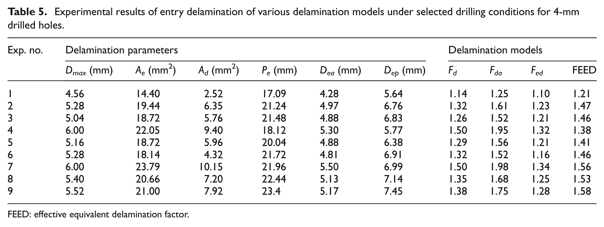
FEED: effective equivalent delamination factor.
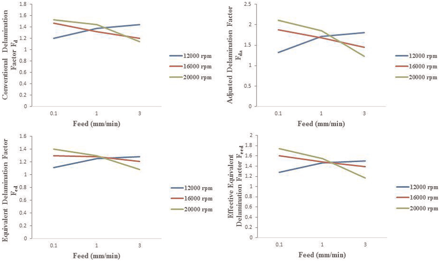
The correlation between various delamination factors at different spindle speeds and feed rates for push-out delamination of 5-mm drill.
The correlation between various delamination factors at different spindle speeds and feed rates for peel-out delamination of 5-mm drill.
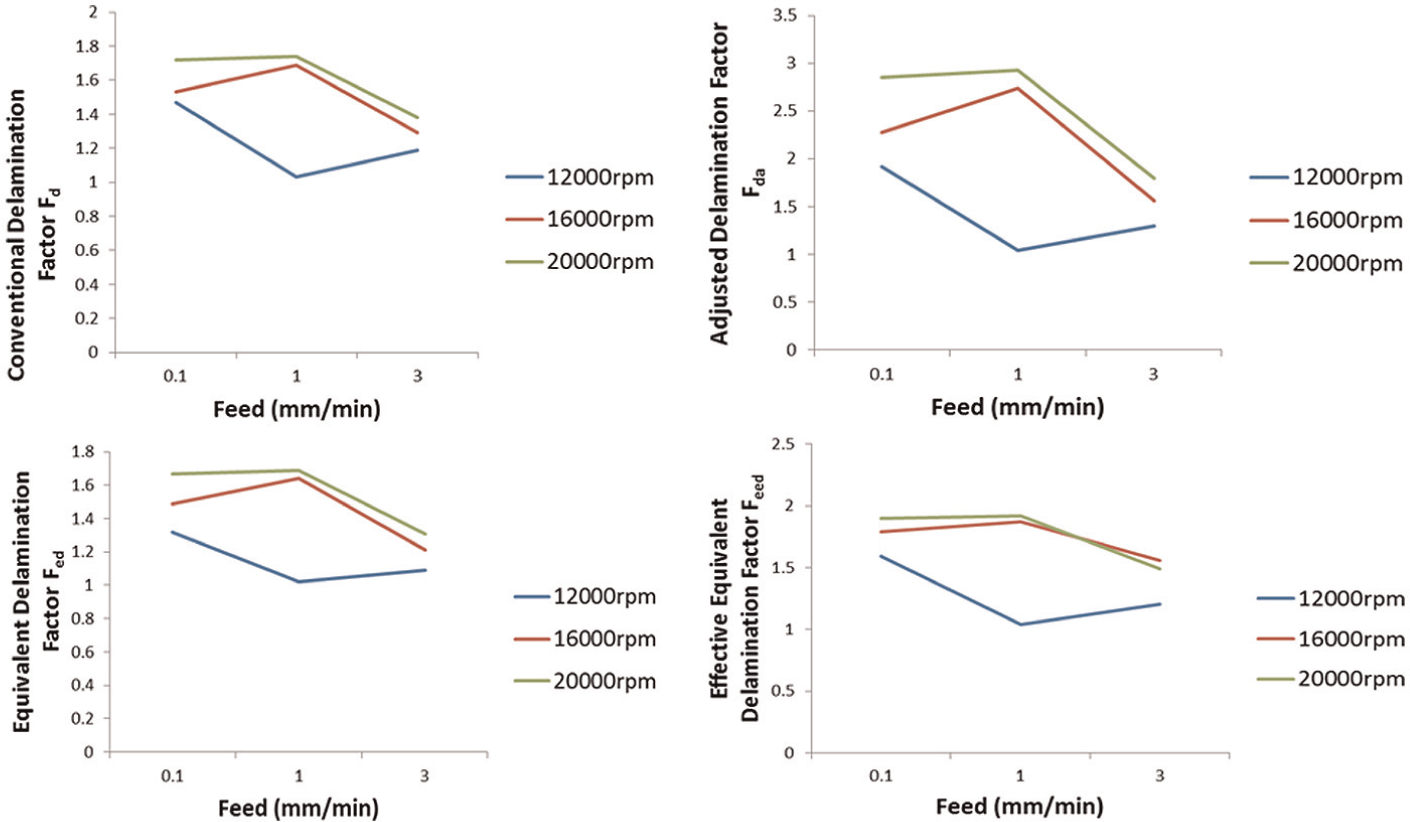
The correlation between various delamination factors at different spindle speeds and feed rates for push-out delamination of 4-mm drill.
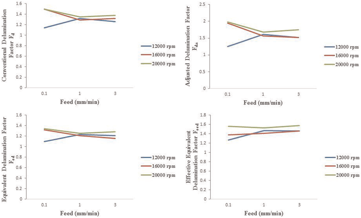
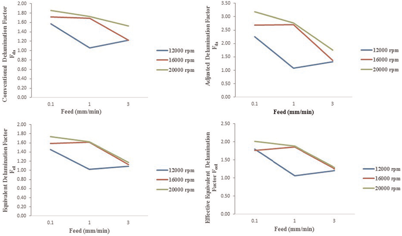
The correlation between various delamination factors at different spindle speeds and feed rates for peel-out delamination of 4-mm drill.
Effect of spindle speed and feed rate on delamination
It can be noted from Tables 2–5 that as the spindle speed increases, the delamination also increases. Similar results are observed by Krishnaraj et al. 41 This may be attributed to the high heat generation while drilling at high spindle speeds and consequent softening of the laminate matrix that can lead to initiation of delamination at lower cutting forces.
From Table 2 (exit delamination for the 5-mm drill diameter), it can be noted that delamination is higher at the lower feed rate of 0.1 m/min. The heat generated at high spindle speeds is concentrated at the surface of the hole as the conductivity of the epoxy matrix is poor. 43 This heat is not transferred to the laminate, and the heat concentration can cause matrix burning when feed rate is low. 42 The results of Rawat and Attia 42 confirm that at the low feed rate of 20 μm/rev and high spindle speed of 15,000 r/min, delamination is high, but on increasing the feed rate to 60 and 100 μm/rev, the delamination decreases.
This study reveals that for the spindle speed of 12,000 r/min, the delamination reduces when feed rate increases from 0.1 to 1 m/min. But with the feed rate of 3 m/min, it reverses the trend. This indicates that at spindle speed of 12,000 r/min, the lowest delamination occurs at the feed rate of 1 m/min. For spindle speeds of 16,000 and 20,000 r/min, the optimum feed rate is 3 m/min for lowest delamination. Recent experiments of Pinho et al. 44 with drill bits classified by them as A, B, and C show that for peel-up delamination, the factor value decreases as feed rate increases. In case of push-out delamination, there is no clear trend. At the spindle speed of 7500 r/min, with drill bit C, the push-out delamination decreases with increasing feed rates up to 0.2 mm/rev. Then, it increases at 0.33 mm/rev feed rate. For the drill bits A and B, the trend is the same. The results presented by Grilo et al. 45 also show that the effect of feed rate on push-out delamination is not clear.
Higher feed rates increase the thrust force even at high spindle speeds. 46 Also at higher spindle speeds, because of material softening, delamination can be initiated even at a lower thrust force. 41 Whether or not the combined effect of increased thrust force and matrix softening can be the reason for reversal of delamination trend is a question that needs further investigation.
Results of Campos Rubio et al. 47 also confirm different feed rates for lowest delamination at different spindle speeds. Their paper shows that the Fd value is the lowest at 9 m/min for a twist drill of point angle 115°, 6 m/min for a twist drill of point angle 85°, and 3 m/min in the case brad and spur drill, when the spindle speed is 40,000 r/min. This points to a relationship among the point angle, spindle speed, and feed rate that influences the delamination factor. In other words, for the same point angle with different spindle speeds, the lowest delamination damage happens at different feed rates. The mechanism of damage is dependent on cutting parameters: spindle speed and feed rate. Also, the delamination damage is influenced by heat generation at high spindle speeds, and the time span of this accumulated heat at the surface to cause the matrix burning. This cutting time depends on the feed rate.
Temperature rise in drilling may play a major role in the delamination of composite materials. Moderate increase in temperature may reduce the delamination but further increase in temperatures nearer or above the glass transition temperature reduces the strength of the composite material and may cause increase in delamination. 48 The general trend is that as spindle speed/cutting speed increases, the temperature of the cutting zone and the tool rises; this rise in temperature may have positive or negative effect on the delamination damage (work piece). Gaitonde et al. 49 present that cutting force acting on the peripheral direction is the main driving force for the delamination. This rise in temperature may also alter the dimensions/geometry of tool, and the efficiency of the coating material, which in turn affect the overall performance of the drilling operation. Khashaba 50 states in his review paper that the effect of matrix softening on delamination with respect to thermal and mechanical damages has not yet been fully investigated and problems remain to be solved.
From Table 4 (exit delamination for the 4-mm drill diameter), it can be noted that delamination is higher at higher feed rates for a spindle speed of 12,000 r/min. This spindle speed does not generate sufficient heat to soften the matrix; thus, the effect of increase in the thrust force persists, thereby increasing the delamination. Heat generation depends on cutting speed Vc (Vc is 2.5 m/min for 4-mm drill at 12,000 r/min against 3.14 m/min for 5-mm drill). For higher spindle speeds of 16,000 and 20,000 r/min, delamination behaviour is the same as that for the 5-mm drill, as it decreases with increase in feed rate. Cutting speeds for 4-mm drill at 16,000 and 20,000 r/min are 3.35 and 4.18 m/min, respectively. This can mean that ideal drilling condition (lowest delamination) is not achieved within the range of experiments. Therefore, it may be concluded that for smaller drills, a higher spindle speed with suitable feed rate is necessary to obtain good quality holes.
Tables 3 and 5 give the peel-up delamination data for 4- and 5-mm drills, respectively. From these tables, it is observed that all the delamination factors show higher values for 5-mm drills when compared to those for 4-mm drills, as the cutting force is higher leading to the pulling up of the fibres. Delamination is mainly influenced by the thrust force. The softening of the matrix due to the temperature has little influence. However, the peel-up delamination is lower as compared to the push-out delamination. From Tables 3 and 5, it can be noted that delamination does not show any clear trend with feed rate. But higher spindle speeds show higher delamination. These results are in good agreement with those of Krishnaraj et al. 41
Comparison of delamination factor models
From Tables 2–5, it can be observed that adjusted delamination factor is the highest, followed by FEED and conventional delamination factor, while the equivalent delamination factor is the lowest. It can be further noted that at an ideal drilling condition (lowest delamination) with the combination of spindle speed 12,000 r/min and feed rate 1 m/min (Exp. no. 2 in Tables 2 and 3), the values of all the delamination factors, including the adjusted delamination factor, are nearly the same, as described in section ‘Proposed delamination factor’. It shows that the proposed delamination factor will give the same results as the earlier methods for uniform delamination damage and improve the accuracy of results for irregular delamination damages.
The delamination factor models, except Fed, consider indirectly, increase in diameter of the hole in the assessment of delamination factor.
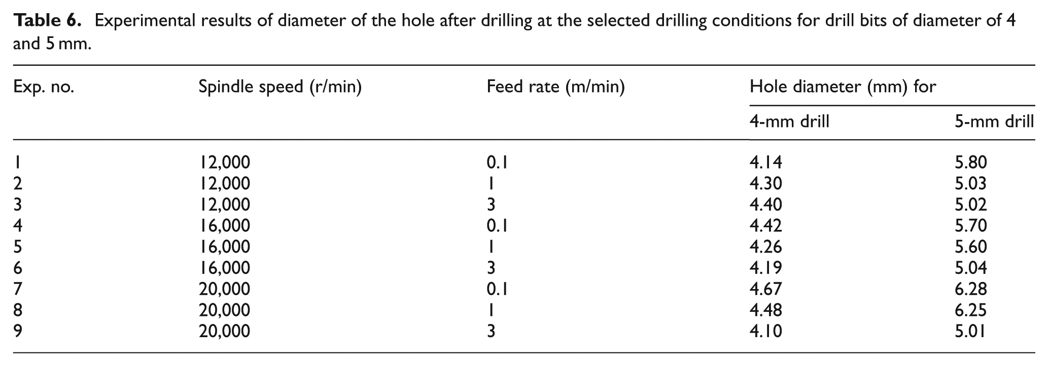
Experimental results of diameter of the hole after drilling at the selected drilling conditions for drill bits of diameter of 4 and 5 mm.
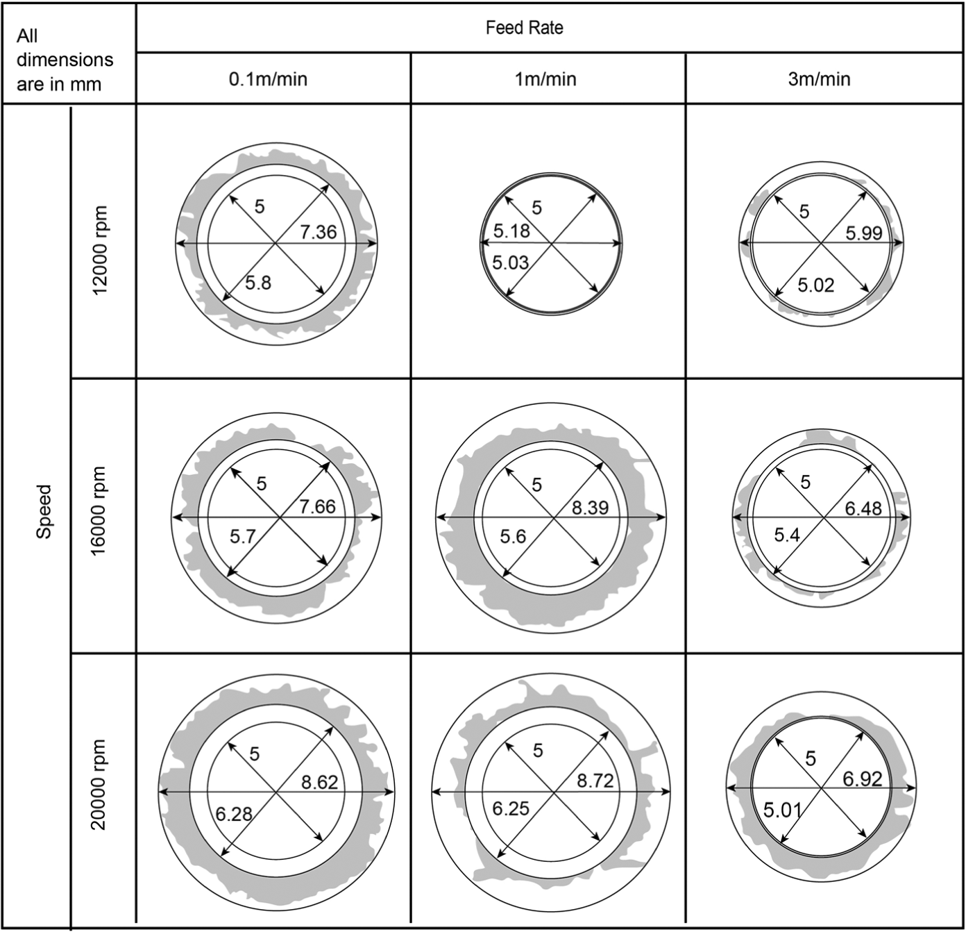
Processed images of drilled holes drilled at different spindle speeds and feed rates indicated with nominal diameter, diameter of the hole drilled, and maximum diameter.
In this study, Fed values also show the same trend of decreasing delamination with increasing feed rate till an optimum level is reached. Further increase in the feed rate results in higher delamination. This indicates that the heating of the matrix at high spindle speeds and low feed rates not only increases the diameter of the hole but also causes the pull out of fibres in the vicinity of the hole (Ad). Similar results on the damaged area in the vicinity of the hole (Ad) can be observed from the results of Campos Rubio et al. 47 in which for the test runs 9–12 with the spindle speed 40,000 r/min and feed rates 1, 3, 6, 9 m/min, the delaminated areas Ad are 7.100, 5.670, 4.998, and 5.310, respectively. This indicates that delamination decreases with feed rate up to 6 m/min and then increases at feed rate 9 m/min as explained earlier.
This study results show that all the delamination factors considered, that is, conventional, adjusted, equivalent, and proposed FEED, show the same trend of delamination for all the spindle speed and feed rate combinations. However, the adjusted delamination factor shows higher values because of its additive formula, and the equivalent delamination factor shows the lowest values as it considers only damage area in the assessment. Proposed FEED shows higher values when compared with conventional delamination factor (which considers only the maximum diameter of the damage in the assessment) and equivalent delamination factor (which considers only the damage area in the assessment), but shows lower values than the adjusted delamination factor (which considers both damage area and maximum diameter of the damage in the assessment). FEED, even while taking into account both the damaged area and the crack length in the calculation of the delamination factor, gives the moderated value in comparison with the adjusted delamination factor and hence it may be considered a better factor for the assessment of delamination. Future work can involve comparative evaluation of the factors by conducting experiments with strength tests.
Conclusion
Delamination is one of the critical factors in the assessment of the quality of the drilled hole in composites. A comprehensive analysis of various delamination factor models, including a proposed improved model – FEED, after drilling GFRP composites in high-speed drilling with twist drill, is presented in this article. The conclusions drawn from this study are as follows:
Adjusted delamination factor value is the highest, followed by FEED and conventional delamination factor, while the equivalent delamination factor is the lowest.
As against the equivalent delamination factor, which is lower than the conventional delamination factor, FEED shows a higher value when compared with the conventional delamination factor.
The values of FEED lie in between those of equivalent delamination factor and adjusted delamination factor.
The optimum combination of feed rate and spindle speed for lowest delamination is the feed rate of 1 m/min with spindle speed of 12,000 r/min. For other spindle speeds of 16,000 and 20,000 r/min, the optimum feed rate is 3 m/min for lowest delamination.
Diameter of the drilled hole increases with the increase in spindle speed and decreases with the increase in feed rate mainly due to the thermal destruction of the composite at high spindle speeds with low feed rates.
The maximum diameter of the hole was obtained at the low feed rate (0.01 m/min) and at the high spindle speed (20,000 r/min) for both 4- and 5-mm drills.
The trend of the push-out delamination factor for 5-mm drill with change in feed rate is not clear, as it is decreasing and then increasing with increase in feed rate for spindle speed 12,000 r/min; increasing and then decreasing with increase in feed rate for spindle speeds 16,000 and 20,000 r/min.
The peel-up delamination with 4-mm drill shows increasing trend with feed rate for a spindle speed of 12,000 r/min. For higher spindle speeds of 16,000 and 20,000 r/min, delamination behaviour is the same as that for 5-mm drill.
Peel-up delamination does not show any clear trend with feed rate. But higher spindle speeds show higher delamination than at lower spindle speeds for both the drill bit sizes.
All the delamination factor models show the same trend with the selected spindle speeds and feed rates.
Proposed delamination factor, FEED, even when taking into account both the damaged area and the crack length in the calculation of the delamination factor, gives a moderated value in comparison with the adjusted delamination factor and hence it may be considered a good measure for the assessment of delamination.
Footnotes
Appendix 1
Declaration of conflicting interests
The author(s) declared no potential conflicts of interest with respect to the research, authorship, and/or publication of this article.
Funding
The author(s) received no financial support for the research, authorship, and/or publication of this article.