
Abstract
Strength and load-bearing capacity of dissimilar joints welded by friction stir welding is one of the most interesting subjects for optimizing this recently developed joining technique. Hence, in this article, dissimilar butt weldments of pure copper with Al5083 are manufactured with different welding parameters (including pin rotational and tool offset). Then rectangular beam specimens containing right angle notches in the interface of joints were prepared from the welded plates and tested under three-point bend loading to investigate the interface fracture strength of Al–Cu joints. The results showed the significant influence of welding parameters on the strength and load–displacement curves of the tested bimetals. It was shown that considering a suitable value for the offset of pin can increase the interface fracture strength. The highest fracture loads were achieved at moderately lower pin rotational speeds.
Keywords
Introduction
Joining of metals and materials is an important stage in manufacturing and assembling of industrial and engineering parts. Although fusion welding techniques such as arc welding and oxyacetylene welding have been widely used in the past for metal joining in industrial and structural applications, some shortcomings including high risk of defect formation, significant amount of distortion, high residual stresses and initiation of catastrophic failures in the welding zone have limited the application of conventional fusion welding processes, specially for high-tech applications such as those used in aerospace structures. For overcoming the mentioned limitations, “The Welding Institute” (TWI) proposed a thermo-mechanical solid-state welding method called friction stir welding (FSW). In this method, the metal is not melted and a non-consumptive tool is used for joining two facing surfaces. During the rotation of the tool, heat is generated between the tool and the materials to be joined which leads to creation of a very soft region near the rotating tool. The two pieces of metals are then mechanically intermixed at the place of joint. By further applying a mechanical pressure and due to the induced heat by friction of the shoulder surfaces, the softened metals can be joined together. This method has been known to be a very suitable and versatile technique for welding of low fusion weldable materials such as aluminum alloys that are usually hard to be joined by fusion welding processes. Kishta and Darras 1 successfully welded 5083 marine-grade aluminum alloy by FSW technique at underwater environmental condition and presented the temperature history for different FSW process parameters. Based on their results, underwater welding of AA5083 alloy produced good tensile properties, and also significant reduction in void fraction was observed in the weld zone. FSW tailor welding process of Al6061–Al5083 blank sheets was optimized by Ghaffarpour et al. 2 using response surface methodology. Nguyen et al. 3 predicted failure loads of friction stir spot welding joint of Al6061-T6 sheets using finite element analyses. Rajakumar et al. 4 also performed a study for optimizing the FSW of Al7075 plates and presented empirical relationships between the FSW and its tool parameters and the tensile strength of FSW joints. They used a number of techniques such as design of experiments (DOE), variance, regression and sensitivity analyses to estimate the errors and uncertainty values of FSW process. Simoncini et al. 5 developed an innovative dual-side FSW methodology to improve the post-welding formability of AA6082 joints. Subramaniam et al. 6 studied the influence of three pin profiles (i.e. square, circular and triangular shapes) on the quality of AA6063-T6 FSW welded plates. They also used acoustic emission technique for monitoring the pin parameters on the tensile strength value. Zhou et al. 7 proposed a novel distributed cooling method for reducing the residual stresses of FSW process. Kasman and Kahraman 8 studied the mechanical and microstructure of AA5083-H111 FSW joint using a tool with triangular pin. Chen and Kovacevic 9 analyzed numerically the stress evolution of FSW process for 6061 aluminum alloy. Fratini et al. 10 compared the bending strength of aluminum T-joints fabricated by the FSW and metal inert gas (MIG) welding methods. The influence of the process parameters on fatigue resistance of AA6082-T6 alloy was studied experimentally by Cirello et al. 11 Similarly, Zhang et al. 12 studied the effect of FSW residual stress on fatigue crack growth behavior by testing two test-type specimens made of AA2024-T351. Bahemmat et al. 13 studied the influence of friction stir pin profile and tool rotational speed on micro- and macro structures, micro hardness, ultimate tensile strength and elongation of 7075-T6 joints fabricated by the FSW method. Barletta et al. 14 presented the experimental results of the local mechanical and morphological characterization, post-weld and softening effects on butt joint FSW of AA6082-T6 alloy.
Joining of dissimilar materials which is widely required in many industrial applications such as power generation, petrochemical, nuclear, aerospace, transportation and electronics industries is also another ability of the FSW. While most of the conventional welding methods fail to produce high-quality dissimilar weldments due to different thermal, chemical and mechanical properties of two materials in the weld zone and also formation of brittle inter-metallic compounds, it has been demonstrated that the FSW is able to provide sound dissimilar joints such as steel/magnesium, 15 copper T2/Al5A06, 16 AZ13B magnesium/Al6061, 17 6061-T6/AISI 1018 steel, 18 Al6013-T4/X5CrNi18-10 stainless steel 19 and Ti–6Al–4V/Al6061 or Ti–6Al–4V/Al5A06.20,21 The microstructure and mechanical properties obtained from the aforementioned articles demonstrated the applicability and ability of FSW method for joining a wide range of dissimilar metals. For example, Li et al. 20 fabricated aluminum/titanium clad sheets by multi-pass friction stir lap welding method. They investigated process principles bounding property of aluminum/titanium clad sheets, interlayer structural properties and anti-oxidation performance of Al/Ti–6Al–4V specimens. In another similar work, Zhang et al. 21 studied interface characteristics and tensile strength of dissimilar Al5A06 and Ti–6Al–4V FSW butt joints. They showed that sound quality and defect-free joint are obtained at rotational speed, travel speed and pin offset of 1200 r/min, 60 mm/min and 0.5 mm, respectively. At such FSW process parameters, the maximum tensile strength of the joint was reached to approximately 84% of that of Al5A06 alloy. Elyasi et al. 22 also investigated experimentally the influence of tool tilt angle on FSW properties of A441 steel–AA1100 aluminum alloys. They showed that by increasing the tilt angle, the interaction between two metals, axial force and heat generation values becomes more.
Dissimilar joining of 1XXX to 7XXX aluminum alloy series has also been widely performed and studied in the past years using the FSW. For instance, Guo et al., 23 Palanivel et al. 24 and Kundu and Singh 25 investigated the effect of FSW process parameters on the mechanical properties and microstructure of AA6061–AA7075, AA5083-H111/AA6351-T6 and AA5083-H321–AA5086-H116 joints, respectively. Similarly, Aval 26 performed an experimental study to investigate the effect of pin profile on the tensile properties and hardness of AA6082–AA7075 FSW joint. Using Taguchi method, Koilraj et al. 27 optimized process parameters of joining dissimilar AA2219 and AA5085 alloys fabricated by the FSW method. Saeidi et al. 28 joined successfully dissimilar AA5083-H116 and AA7075-T6 by the FSW and obtained the optimum process parameters including the pin rotational and travel speeds. They also developed a mathematical model using genetic algorithm technique for relating the FSW input parameters and the ultimate tensile strength of joints. Leo et al. 29 presented FSW lap joints of a 7075-T6 stringer and a 2024-T4 skin for different tool travel speeds.
However, other dissimilar weldments such as aluminum–copper (Al–Cu) joints have received less attention in comparison with the Al–Al FSW joints. Based on the recent research works, Al–Cu joints could have a significant role in future electrical cars as electrical conductors and electrode of batteries.30,31 In other industries, these joints can be employed as lead frames, harness and electrical wiring, pipe–tape joints, bimetal lug cables and so on.30,31 In many practical cases, bimetal joints are subjected to mechanical loads, and hence, they should have good strength and suitable mechanical properties to withstand against static, impact, fatigue, thermal, corrosion and vibration loads. Therefore, it is important to investigate the mechanical characteristics of Al–Cu joints before using them in practical and industrial applications. In the past years, some attempts have been performed to study the tensile strength, microstructure, hardness and impact properties of lap and butt welded Al–Cu joints. For example, Abdollah-Zadeh et al. 32 studied experimentally the microstructure of lap-joined Al–Cu weldment using the FSW process and obtained the tensile strength and hardness of weld section for different welding parameters. Ouyang et al. 33 performed similar studies for butt FSW of Cu–Al6061 joints. Bisadi and coworkers34–37 investigated the influence of FSW parameters including tool rotational speed, offset of pin and welding speed on the quality of welded sections, mechanical properties and microstructure of dissimilar Cu–Al5083 joints. Xue et al.38,39 also studied the mechanical properties, microstructure, initiation of defects in the nugget zone and formation of inter-metallic compounds in the interface of a copper–aluminum 1060 joint welded by the FSW. In another research work, the influence of shoulder geometry on the microstructure of Al–Cu butt welded joints was studied. 40 Chen et al. 41 investigated experimentally the FSW of thin-walled aluminum–copper pipes. However, many aspects regarding the mechanical properties, load-bearing capacity and failure modes of Al-Cu FSWed joints are still unknown and open. Further research studies are then surely required. For example, the interface fracture resistance and crack growth behavior of these joints under bend loading have not been studied yet. Hence in this article, the load-bearing capacity of a number of notched Al–Cu samples welded by different FSW input parameters is studied experimentally, and the correlation between the fracture loads and welding parameters is widely investigated.
FSW of Al–Cu bimetals
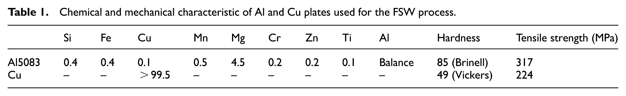
To weld a bimetal made of copper and aluminum materials using the FSW process, first a number of plates with dimensions of 200 mm × 100 mm × 5 mm were prepared from Al5083 and a commercial pure copper. The chemical composition and mechanical properties of the base materials are listed in Table 1. For dissimilar FSW joints, choosing suitable values of tool offset and also location of advancing side (AS) or retreating side (RS) can affect significantly the quality and mechanical properties of the weldments. Usually, the tool offset is considered in the softer material and it is better to place the softer material in the RS.38,39,42–45 According to previous efforts on the FSW of dissimilar metals, it has been demonstrated that when the softer material is placed at the AS, sound FSW (i.e. good quality in both surface morphology and microstructure) is achieved.38,42–45 For example, Xue et al. 38 examined the influence of fixed locations of the AA1060–Cu welded plates and observed that placing the copper (i.e. the softer material) at the RS resulted in very poor quality for the surface of FSW joint along with the creation of tunnel and volume defects. But fixing the Cu plate at the AS produced sound weld with no surface or through-thickness defects. This is mainly due to the fact that during FSW, the materials are transported from the RS to AS.42,46 If the harder material is placed at the RS, the transfer of this material to the AS is difficult because the hard material hardly flowed. Therefore, placing the harder and softer materials at the RS and AS, respectively, leads to a poor joint. However, when the softer material (i.e. Cu in our study) is fixed at RS, it can be transported to the AS more easily with normal flow of material in the nugget zone. Consequently, placing the hard material at the AS can help better mixing of dissimilar materials, resulting in sound weld quality. 42 Hence, for preparing the bimetal Al–Cu joints of this research, the aluminum and copper plates were fixed inside the welding fixture at the AS and RS, respectively, as shown in Figure 1 and vertically milled. The traverse speed of the mill was 40 mm/min along the welding line. To investigate the influence of offset on the load-bearing capacity of the created bimetal joints, the offset values of 0, 1 and 2 mm were considered in the copper plate during the FSW process. A simple cylindrical pin (with diameter of 5 mm and height of 4.7 mm) made of a heat-treated H13 steel with a shoulder having 20 mm diameter and concavity of 6° was used as the welding tool. The tilt angle between the tool and vertical direction was set at the fixed value of 3°, and also the rotational speed of tool was considered variable and equal to 630, 800, 1000 and 1250 r/min. After welding, quality control of weldments was performed using visual inspection of surfaces, optical microscopy and scanning electron microscope (SEM) analyses.
Chemical and mechanical characteristic of Al and Cu plates used for the FSW process.
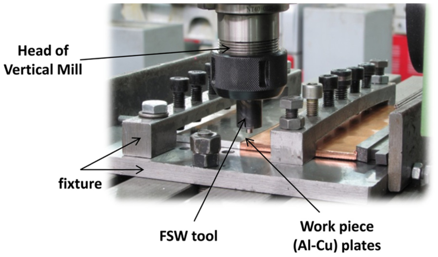
FSW setup for butt welding of Al–Cu plates.
Notch fracture testing of Al–Cu bimetals
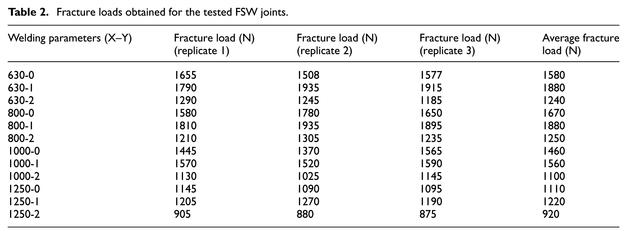
The sound Al–Cu welds (i.e. the specimens without surface and internal defects) were used for notch fracture toughness experiments. For this aim, some rectangular beam shape samples with dimensions of 50 mm × 10 mm × 5 mm were cut perpendicular to the weld line from the welded plates. A right angle notch with height of 2 mm was cut using wire cut machine at the interface of Al–Cu bound of each specimen (see Figure 2 for schematic representation of the prepared bend samples from the welded zone and also the definition of tool offset). The manufactured samples were then placed inside a three-point bend fixture with a span length of 2S = 40 mm and loaded monotonically using a servo-hydraulic test machine. The cross-head speed was kept constant and equal to 1 mm/min. Figures 3 and 4 show typical test setup and geometrical dimensions of the test specimens, respectively. The created notch can lead the location of fracture initiation to be started from the notch tip and then can guide the crack propagation along the interface of bimetal. Hence, it was observed that the fracture of all samples was initiated from the notch tip at a critical peak load. By continuing the test, a gradual and slow crack growth along the vertical direction (i.e. the interface of Al–Cu) was observed for all the tested samples. Figure 5 shows the fracture paths for some of the broken samples. For naming the tested samples, the specimens were designated as X–Y in which X indicates the tool rotational speed (r/min), and Y defines the offset value (mm). For each X–Y pair (i.e. welding parameters), three replicates were tested. The obtained results including the average critical fracture loads obtained for the tested samples are presented in Table 2.
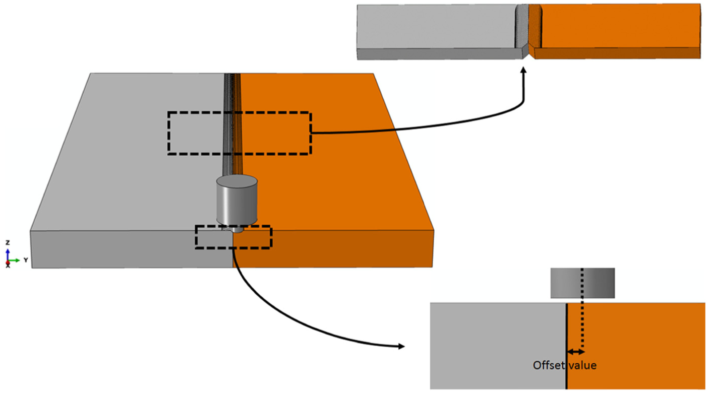
Schematic description of tool offset and the prepared notched bend samples from the welded Al–Cu plate.
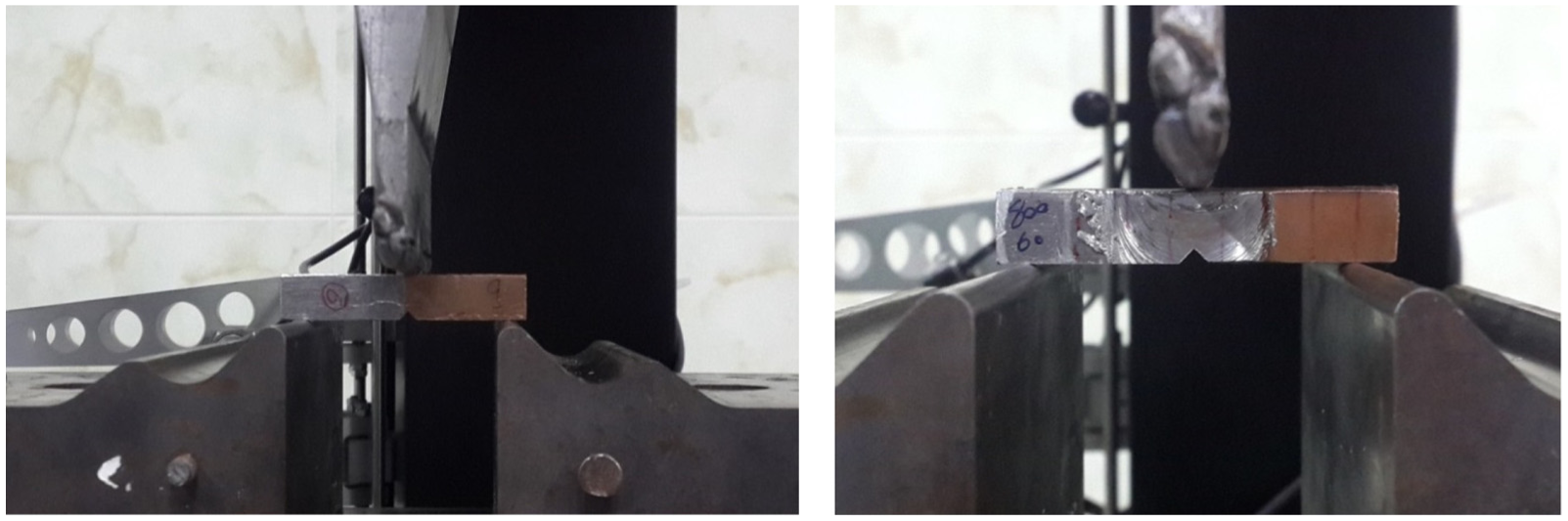
Typical test setup for three-point bend loading of notched Al–Cu bimetals.
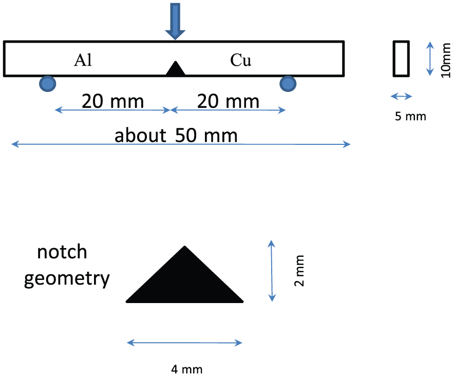
Geometrical dimensions of the bend test sample.
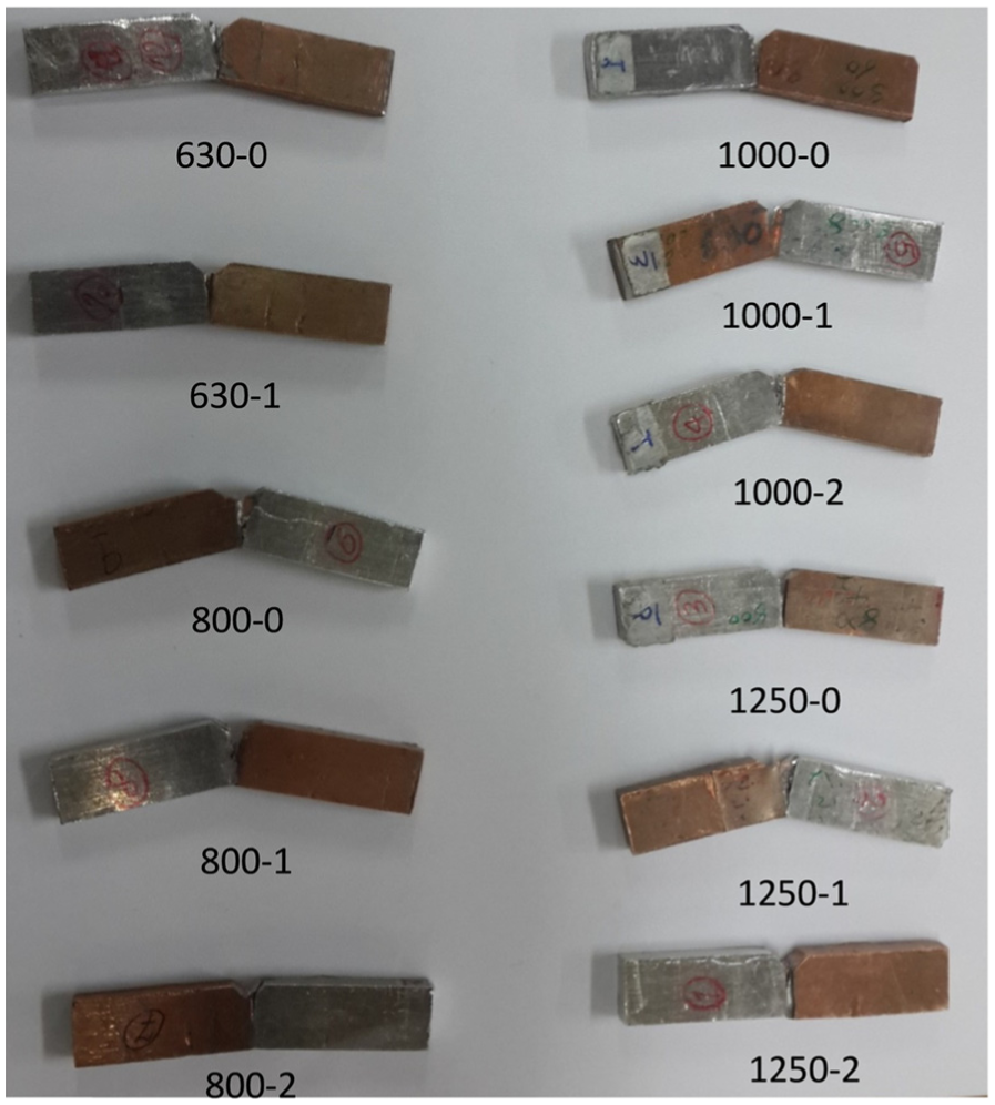
Fracture trajectory obtained for some of the tested Al–Cu bimetals.
Fracture loads obtained for the tested FSW joints.
Results and discussion
The influence of offset value and tool rotation on the load-bearing capacity of the tested bimetals is shown in Figure 6. Based on the obtained data, when the offset of the tool is equal to 1 mm, the highest resistance against fracturing is obtained for different tool rotational speeds, but by further increase in the offset value (i.e. from 1 to 2 mm) the strength of Al–Cu bimetals is reduced. The effect of tool offset in dissimilar joining using the FSW technique can be described as follows. As stated before, due to differences in chemical, physical and mechanical properties between the dissimilar materials, considering a suitable value of pin offset to the softer material can improve the quality of dissimilar Al–Cu FSW joints. For suitable and enough high tool offset values, only few copper particles with relatively small sizes are scratched from the copper bulk that can easily mix into the aluminum base and react with that in the nugget zone. Thus, sound metallurgical bonding would be obtained at the Al–Cu interface of such welds. However, when the tool offset value is small or zero, many large copper particles are stirred into the nugget zone that cannot deform and flow easily in the aluminum matrix.38,39 This can consequently lead to a poor surface bonding with the formation of many voids or defects in the FSW Al–Cu joint. Moreover, under smaller values of pin offsets, more brittle Al–Cu inter-metallic compounds would be formed due to the stirring of more copper pieces into the nugget zone which resulted in poor and lower mechanical properties of created bimetals. On the other hand, at very large tool offset values, the produced FSW joint would exhibit poor strength properties due to the insufficient reaction between the copper particles and aluminum matrix. Consequently, an optimum value of offset can be found for each Al–Cu joint in which the highest interface fracture resistance is obtained. As shown in Figure 6, by changing the offset value from 0 to 2 mm, the highest interface notch fracture resistances were achieved at offset value of 1 mm for all tool rotations. Similar observation was reported by Xue et al., 38 for the tensile properties of dissimilar Al–Cu joints, where they varied the offset values from 0 to 3 mm and concluded that the maximum tensile strength of the joints is achieved when the offset value was between 2 and 2.5 mm.
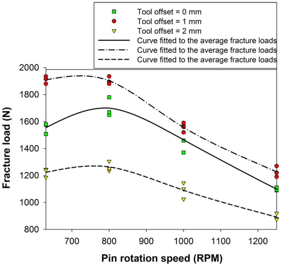
Variations in fracture loads for the tested Al–Cu joints and for different welding parameters.
Furthermore, as can be seen from Figure 6, by increasing the tool rotational speed up to 800 r/min, the joint strength increases and then its resistance against notch fracture becomes smaller for higher tool rotations. In other words, the highest notch fracture strength was obtained at rotation of 800 r/min for all the offset values.
At the speed of 630 r/min, which is relatively low, the mechanism of joining the two metals is mainly a mechanical mixing that creates a layered-type microstructure in the weld zone (i.e. formation of copper layers inside a matrix of aluminum). Copper particles existing inside the matrix are also elongated and oriented along the direction of layered texture as seen from optical micrographs (OMs) of Figure 7. Consequently, at low levels of tool rotation (i.e. in the range of 630–800 r/min), a small increase in the pin rotational speed up to 800 r/min can improve the mixing quality of layered metals in the welded area and hence can increase the strength of Al–Cu joints. However, as the speed of pin is increased, the amount of layered copper microstructure inside the aluminum matrix becomes smaller. As a consequence of that, at speed values higher than 1000 r/min, layered Al–Cu structures are not observed in the welded zone (see Figure 8). This behavior can be due to increase in the temperature of weld zone at such high speeds which can lead to the softening of the joined materials and better mixing of them. However, due to greater mix capacity of materials at high temperatures, brittle inter-metallic compounds are formed instead of a layered microstructure which can reduce the notch fracture strength of the manufactured Al–Cu joints. It worth mentioning that before conducting the notch fracture experiments, the FSW parameters (e.g. tool traverse and rotational speeds, offset value and even pin shape and its geometry) were primarily investigated to obtain a suitable range of welding parameters for sound bimetal Al–Cu joints with no defects. Therefore, as demonstrated by the OMs and SEM pictures (i.e. Figures 7 and 8), the utilized input welding parameters were all in the acceptable window of correct parameters for the investigated bimetals and produced good welds without defects. However, choosing input parameters out of the range of acceptable window may result in low quality or unsuitable joints. For example, Figure 9 shows the surface quality of two FSW Al–Cu joints with different tool rotational speeds. As seen from Figure 9(a), when the tool rotational speed is high enough, a very sound joint is achieved but insufficient heat input at low tool rotations (such as 200 r/min) can lead to poor quality of weld (Figure 9(b)).
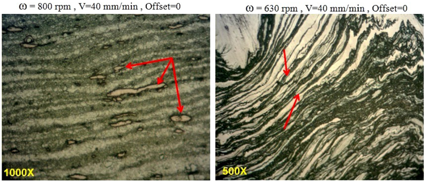
Optical microscopy taken from the weld zone of Al–Cu joint welded by low-speed pin rotations showing layered-type microstructure.
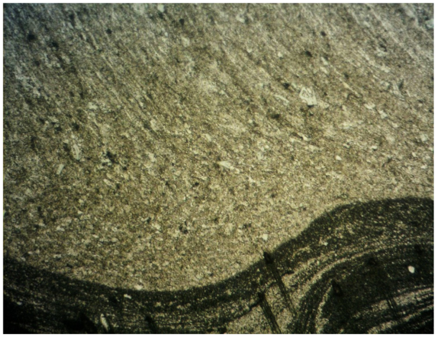
Non-layered microstructure observed for Al–Cu joint welded by higher pin rotational speeds.
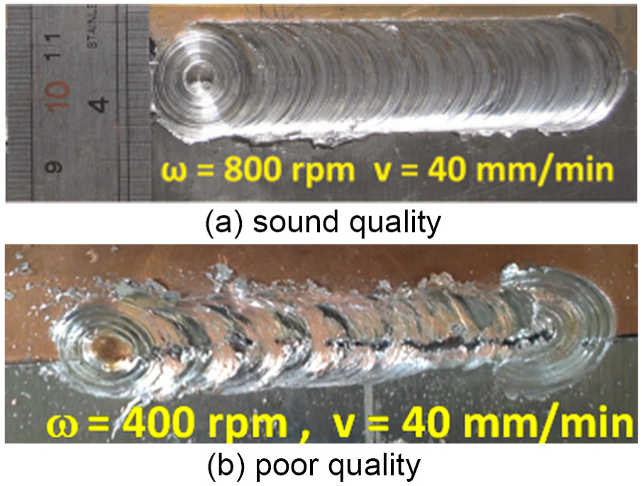
The influence of tool rotational speed on the quality of FSW Al–Cu joints.
Furthermore, as it is obvious, plastic deformation and friction between the tool and the workpiece lead to heat generation during FSW. The total heat generation in this process is the sum of (1) heat generated at the tool pin side, (2) heat generated at the tool pin tip and (3) heat generated under tool shoulder and can be determined from the following equation47,48
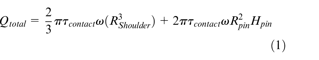
where Rshoulder is the shoulder radius, Rpin is the pin radius, Hpin is the pin height, ω is the rotational speed and

where μ, p and δ are the friction coefficient, contact pressure and contact state variable, respectively. Therefore, according to equation (1), the heat generation during the FSW process can be explained in terms of the tool geometry and its rotational speed. Consequently, although the amount of heat input is a key parameter in the quality, strength and microstructure of the created Al–Cu bimetals, direct measurement of this parameter is not easy during the FSW process and requires special and extra devices (such as thermocouples and infrared heat sensors). Therefore, in this research, it is preferred to present the variations of fracture loads in terms of a more common and available input parameter (i.e. welding speed) which can be measured directly instead of other parameters such as heat input.
Typical load–displacement curves obtained from the tested notched three-point bend Al–Cu bimetal joints have been compared in Figure 10. For lower tool rotations, the created joint (with ductile layered microstructure) exhibits a significant plastic behavior. On the other hand, the primary investigation of this research demonstrates that by increasing the tool rotation speed, nearly linear and quasi-brittle load–displacement curves are observed for the tested Al–Cu joints due to the formation of brittle inter-metallic compounds. However, future studies are necessary to investigate more in detail the parameters involved in the process and the loading capacity of the bi-material welding tested under different combinations of loadings.
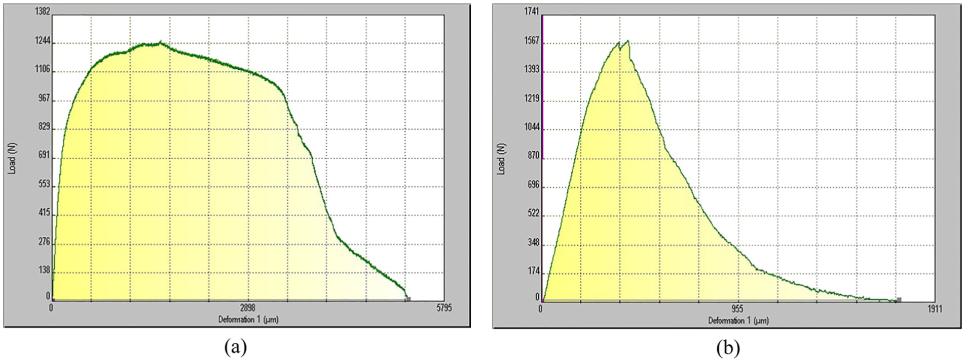
Load–displacement curves obtained for the tested Al–Cu bimetals for pin rotation of (a) 630 r/min and (b) 1000 r/min.
Conclusion
A study of dissimilar butt welded joints of pure copper together with Al5083 is performed considering different welding parameters (including tool rotational and linear speeds and also the tool offset).
Notch fracture resistances at the interface of Al–Cu joints were obtained experimentally using rectangular beam specimens subjected to three-point bend loading.
The results have shown the significant influence of welding parameters on the strength and load–displacement curves of the tested bimetals, and higher values of the fracture loads were obtained at lower values of the tool rotational speeds.
By considering a suitable value for the offset of tool in the softer material (i.e. Cu plate), a noticeable increase in the interface notch fracture strength of investigated Al -Cu joints was achieved.
Footnotes
Acknowledgements
The authors would like to thank Mr Aram Bahmani for his help in preparing this research work.
Declaration of conflicting interests
The author(s) declared no potential conflicts of interest with respect to the research, authorship and/or publication of this article.
Funding
The author(s) received no financial support for the research, authorship and/or publication of this article.