
Abstract
Stiffened panel is a kind of structure that is widely used in aviation manufacturing. Some sheet metal parts in the structure have three characteristics: place-interchangeable, large quantity and stochastic variation caused by spring back or distortion in manufacturing process, which prominently impacts the assembly variation. In order to minimize the influence and improve the assembly quality of stiffened panel, a model based on flexible beam is established and a simplified and approximate assembly variation prediction method is obtained. Furthermore, for the interchangeable sheet metal parts, the assembly location optimization method based on the algorithm of perfect match of weighted complete bipartite graph is proposed. At last, case study on a fuselage panel assembly is implemented. The finite element analysis results show the reliability of the simplified variation prediction method and the necessity of assembly location optimization.
Keywords
Introduction
Due to the various factors in the manufacturing process, there is always a random deviation between the real and the ideal part. The deviation reduces the accuracy of the assembly, generates forced assembly stress, possibly transfers and diffuses in subsequent process. Finally, the quality of the assembly is debased. Assembly variation is a major challenge in aircraft or automotive industry, where sheet metal parts are widely used. According to the statistics, there is 65%–70% of design changing or failure due to inaccurate prediction of the geometry size at the design stage. 1
Since 1990s, assembly variation analysis and prediction have been developed and used in the mechanical industry. Liu and Hu 2 analyzed the assembly process, linearized the variation relationship between the part and the assembly and proposed the method of influence coefficient (MIC). Cai et al. 3 amended the MIC to deal with the non-linear frictional contact interaction between the parts or jigs.4–7
In recent years, the MIC has been further studied and widely used in assembly planning, optimization, evaluation, variation source identification and product-oriented sensitivity analysis.8–12 Based on the MIC, Camelio proposed the state space method according to multi-step or multi-station assembly process, which is used to not only simulate the compliant assembly but also control or improve the process.13–15
Huang et al.16,17 divided the variation source into three categories: fixture variation, part variation and assembly sequence. From the traditional point of view, there are also three corresponding methods for reducing the variation: increase accuracy and stiffness of fixture, improve accuracy of parts and optimize assembly sequence. Nowadays, the development of software and hardware technology makes new method improving assembly quality for some special structure possible. Yang presented an optimization technique in straight-build assembly to control variation propagation in an aero-engine assembly. 18 Liao proposed an algorithm of clamp shimming optimization for minimizing sheet metal assembly deformation. 19 This article is running on this line for dealing with reducing the assembly variation of stiffener panel, which is widely used in aviation manufacturing. It is well known that the shape and the performance of the panel must meet some high technological requirements. In the structure, there are great amounts of stiffener parts, such as frames, clips and stringers, which are designed as possible as meeting the interchangeability for economic. In the manufacturing process of these sheet metal parts, due to the existing of spring back and distortion, blindly pursuing the accurate is not only technically difficult but also uneconomical. Nevertheless, it would be a good choice to shift the focus from the part manufacturing stage to the assembly stage.
The remainder of this article is organized as follows. Section “Beam-based assembly model” establishes the assembly model based on continuous flexible beams. In section “Location optimization,” a simplified and approximate method for calculating assembly variation is obtained. Then, based on a graph theoretical algorithm, a method of assembly location optimization of place-interchangeable sheet metal parts is proposed. In section “Case study: assembly of a fuselage panel,” a case study on a fuselage panel is implemented to verify the validity and necessity. Section “Conclusion” draws the conclusions.
Beam-based assembly model
For the vast majority sheet manufacturing process, the main source of the dimension problem lies in the deformation of the normal direction. 19 In the assembly process, six freedoms of the sheet metal part are constrained by the fixtures or the other components. Generally, the parts should experience the PCFR (place, clamp, fasten and release) cycle or PCMR (place, clamp, measure and regulate) cycle. 20 The migration of the boundary conditions and the loads is shown in Figure 1.
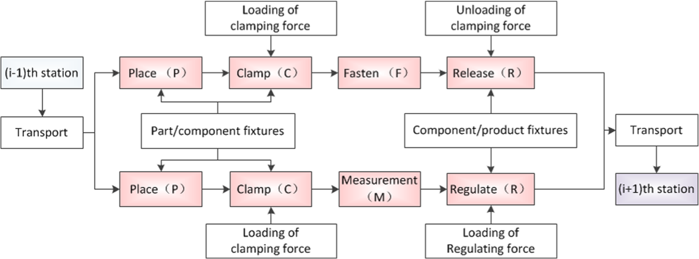
Migration of boundary conditions and loadings in assembly process.
Variational straight beam could be regarded as another configuration obtained from a non-variational beam, under a certain loading with a certain boundary. Beams with different variations could be regarded as different configurations. While the amount of the variation is small, it can be assumed that the size of the variation is proportional to the required load for eliminating the variation, as shown in Figure 2.
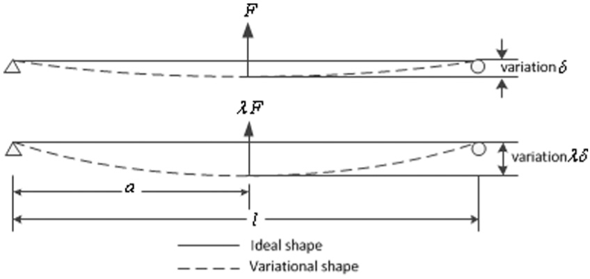
Proportional relationship between variation and forced assembly load.
Before establishing the beam-based assembly model, we give another reasonable hypothesis: if there is only a little difference between two configurations (a) and (b), then A and B could be obtained from each other by putting on the loading with same magnitude but inverse direction under a given boundary condition, as shown in Figure 3.
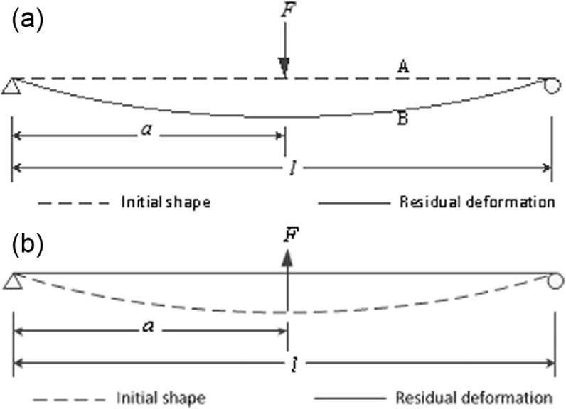
Hypothesis of relationship between the inversed configurations.
Generally, a traditional assembly process includes four stages: place, clamp, fasten and release, as shown in the left section of Figure 4. The non-variational part 1 is a short, straight beam with length
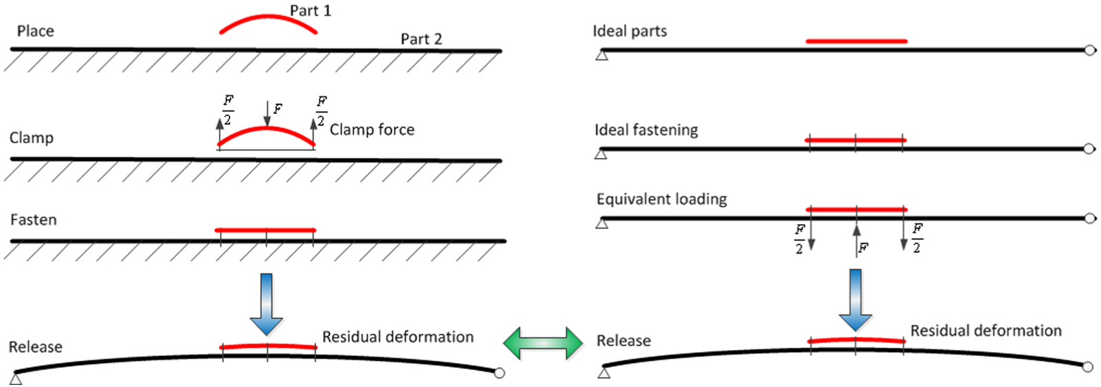
Illustration of the approximately equivalent assembly processes.
Might as well, the variation corresponding to the unit loading
It can be known from the above hypothesis that the minimal load for eliminating the variation is the force
After the assembly process, the clamping force for eliminating the variation is released, and the variational parts with ideal shape tend to spring back to initial shape. Due to the joints, the trend is prevented by the other parts or components. The inner force generated by the trend is equivalent to the inversed minimal clamping force. Simulating the assembly process includes four stages, and requires multiple steps, which is not only because of the loading and unloading of the clamping force but also because of the changing boundary condition. But if the minimal clamping force is obtained, then it is inversed and applied on the connection points of the assembly consisted of non-variational parts, and the variational assembly is obtained. Finally, assembly variation analysis with multiple steps could be reduced to single step, as shown in the right section of Figure 4. Finite element analysis of assembly variation will be greatly simplified.
Location optimization
With referencing the stiffened panel, consider the assembly process of
Question. How to find the assembly distribution for a set of variation-known and interchangeable parts to minimize the assembly variation?
If there is only one variational short beam assembled and the influence of the joint between the different short beams is ignored, the assembly variation could be obtained by putting the inversed clamping force on the connection points, as shown in Figure 5. The residual deformation or the assembly variation is evaluated by measuring the variations of
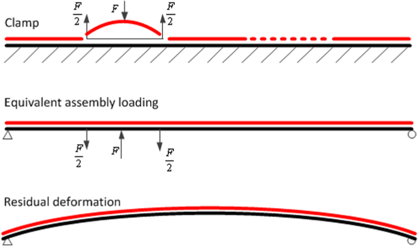
Equivalent assembly process of single variational short beam.
The assembly variation or the residual deformation could be evaluated by the following three indexes:
Two-norm of the variation vector:
Determinant of the covariance matrix of the variation vector:
Largest eigenvalue
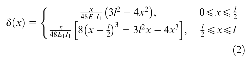
Without loss of generality, the first index is used in the following analysis and discussion. Then, according to the MIC, the assembly variation caused by the short beam with variation
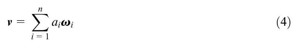
According to the principle of superposition, after assembling all short beams, the assembly variation is
Assembly location optimization problem is that find the best assemble position for each short beam to minimize the assembly variation. Denote the set of parts (or corresponding variations) as X and assembly positions Y, respectively. The negative assembly variation
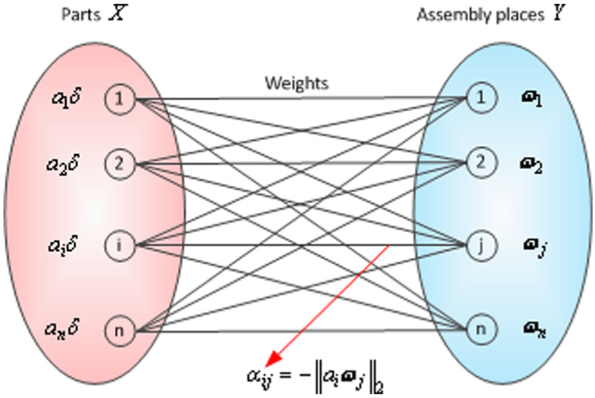
Bipartite graph model of the assembly of place-interchangeable parts.
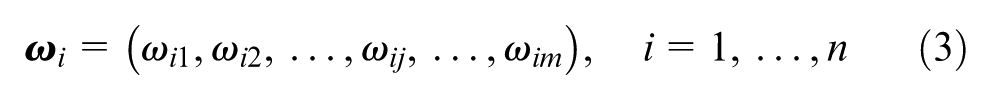
The assignment problem also exists in the process of assembling the variational short beams to a variational long beam. If the variation of the long beam is

where
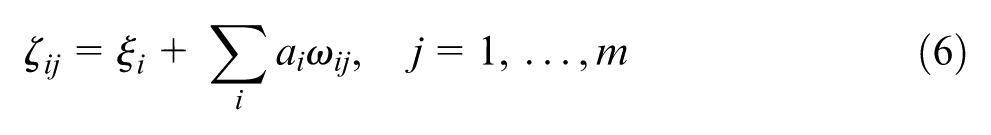
After assembling all short beams, the magnitude of the assembly variation of all measurement points is
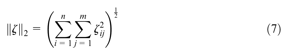
In this case, there is nothing to do but modify the weight
Method. First, calculate the weights, that is, the assembly variation caused by assembling the unit-variational part at every assembly position. It is needed to emphasize that the unit variation is corresponding to the unit load but concrete unit load is not unnecessary. Second, solve the assignment problem for finding the perfect match between the part variation and the assembly position.
Case study: assembly of a fuselage panel
Panel structure and variation source
Spring back is an important reason for obtaining non-accurate shape or geometry size in manufacturing process of sheet metal part. Deviation caused by mold is very small in proportion. This is due to the plastic deformation of the sheet metal part that always includes the elastic component. It may completely fit the mold while the part is pressurized but affirmatively deviate from the mold after eliminating the pressure. Because there are many influence factors, the amplitude of spring back is numerically unstable. Distortion is another reason for preventing the accurate shape or geometry size. Plastic deformation of the sheet metal part always develops along the direction with lowest resistance. Thus, deformation may occur on the needless direction.
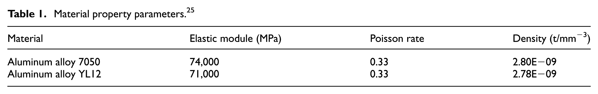
Figure 7 shows a fuselage panel of a prototype aircraft. The panel consists of 1 skin, 6 frames, 7 stringers and 36 clips. Material of the skin is YL12 and the others are 7050 aluminum alloy. Table 1 shows the material property parameters. 25 Yield strengths of the two materials, 350 MPa (YL12) and 450 MPa (7050), are obtained from a series of uniaxial pressing tests implemented according to Liu and Liu’s 26 handbook.
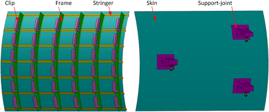
Structure of the fuselage panel.
Material property parameters. 25
After completing the assembly on a gantry with fixture board, the panel is transported to next station for splicing with other panels. In the process of splicing, the panel is supported by three 3-axis positioners with three spherical joints.
According to the engineering practice, the panel assembly must meet the following three requirements:
The variation of the shape of the skin should be within the allowable range, in order to ensure the aerodynamic requirements.
The frame web should be vertical to the inner surface of the skin as possible.
The position of the stringers should be accurate for ensuring the smoothly splicing.
There are two factors found in the assembly process which rather largely impact the result.
One is the larger number of the clips. As shown in Figure 8, the expectation of the angle between surface A and B is 90°. But due to the factor of spring back in the bending process, the angle always exists as a deviation. According to statistics, the deviation is normal distribution and the standard deviation is
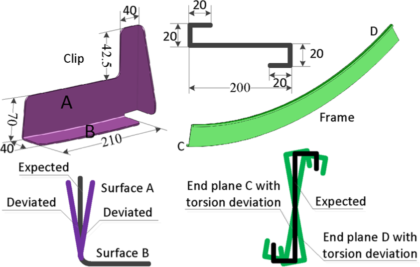
Illustration of clip and frame variations.
The second is the frames, the slender parts obtained from the bending and rolling-bending process. Weak stiffness of the web makes the distortion happen in the rolling–bending process. The variation of the frame is defined as the deviation angle between the end-plane C or D and the expectation. The deviation also is normal distribution and the standard deviation is
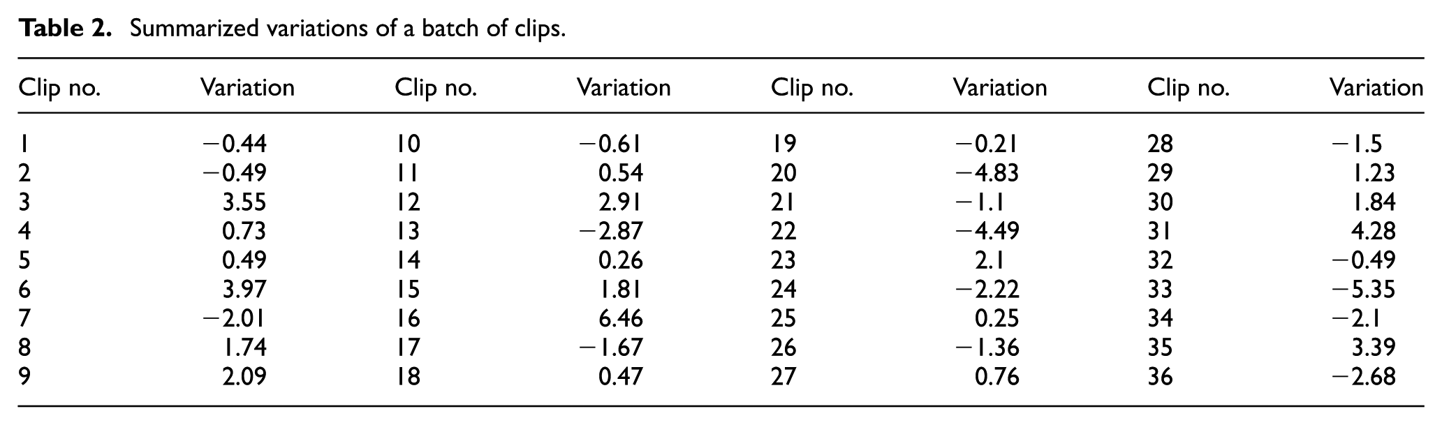
The variations of a batch of clips and frames are summarized in Tables 2 and 3. There is just a little influence on the assembly, hence, the variations of the other parts or the other features are ignored. Furthermore, according to the experience, it is assumed that the variation of the clip could be eliminated by fixing surface A and putting a pressure on the riveting sew of surface B, and similarly, the variation of the frame could be eliminated by fixing the surface C or D and putting a torsion moment on the surface D or C.
Summarized variations of a batch of clips.
Summarized variations of a batch of frames.

Process description
In order to make the panel meet the assembly requirement of the next station as precise as possible, the assembly locations of the frames and the clips are optimized in the case of other process determined. As mentioned above, under a certain boundary condition, the variation of a part is proportional to the clamping force. Thus, the assembly variation caused by putting a unit load on a position is defined as the weight of the unit-variational parts relative to the position. A three-dimensional finite element model is developed to calculate the assembly variation or the weights by utilizing the software ABAQUS/Standard. 27
According to the requirements, 47 measurement points are set for evaluating the assembly quality and divided into the following three parts:
Nine points on the skin represented the shape of the panel;
Four points on each frame represented the angle between the frame web and the inner surface of the skin;
Two points on each stringer represented the position of the stringer.
Finite element simulation for solving the weight is as follows.
The mesh of the non-variational panel and the layout of the measurement points are shown in Figure 9. Element shape of every part is hexahedral. The reduced integration element with enhance Hourglass control is used to ensure the numerical stability. On `Interaction’ module, the TIE constraint is chosen for simulating the riveting joints due to the mating surface between each pair of the neighboring and non-variational parts has the same shape.
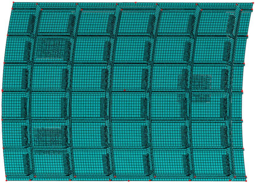
Finite element mesh and the measurement points of the panel.
While the panel is measured or operated in the next assembly station, the panel is supported by three 3-axis positioners with the spherical joints. Thus, the hinged spherical joints are set as the boundary condition in the finite element model.
For the clip, the clamping force or the resilience force is put on the riveting sew, the red area as shown in Figure 10. For the frame, the forced assembly loading is put on the end planes. In the finite element model, a reference point is constructed and set as coupling with each end plane, then a torque is put on the point.
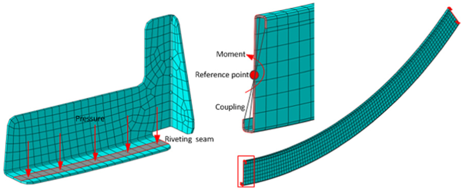
Illustration of location of the forced assembly load.
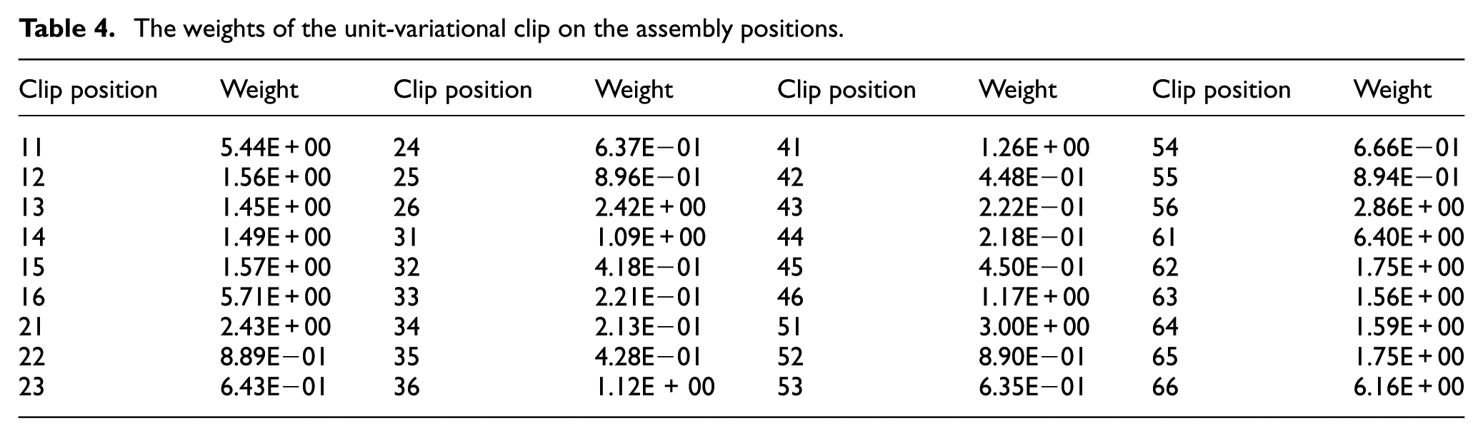
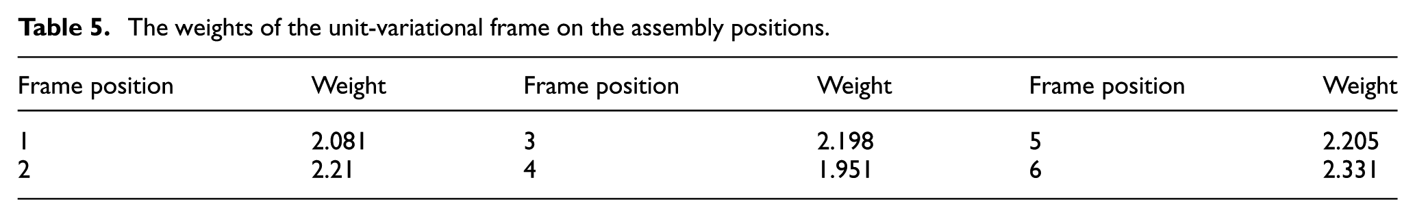
Actually, the load corresponding to the unit variation is not easy to obtain and just the proportion is needed in the assembly location optimization. Therefore, the unit clamping loading 0.1 MPa is assumed for the clip and 10,000 N mm for the frame. The weights of the unit-variational clip and frame on each position are obtained and shown in Tables 4 and 5, respectively. There are 36 assembly positions for the clips and 6 for the frames. According to the rows and the columns, the positions are numbered as shown in the following tables.
The weights of the unit-variational clip on the assembly positions.
The weights of the unit-variational frame on the assembly positions.
Results and discussions
After calculating the weights of the unit-variational part on the assembly positions, based on the Kuhn-Munkres algorithm, the assembly locations of the clips and frames corresponding to the minimal assembly variation (i.e. the best case) and the maximal assembly variation (i.e. the worst case) can be obtained. As shown in Tables 6–9, respectively.
The optimal assembly distribution of the batch of clips.
The optimal assembly distribution of the batch of frames.
The worst assembly distribution of the batch of clips.
The worst assembly distribution of the batch of frames.
For given parts and their certain variations, assembly variation could be predicted by implementing a finite element simulation which includes four steps: positioning, clamping, joining and spring back. 20 Figures 11 and 12 show the results of the best and worst case corresponding to the two distributions mentioned above. It can be seen that the distribution of the variations of the best case is rather more uniform than the worst case. The comparison of the variation of each measurement point is shown in Figure 13. As shown in the figure, mostly all values of the best case are smaller than the worst. Thus, the reliability of the simple method of calculating variation and the necessity of the assembly location optimization are verified.

Variation contour of the panel corresponding to the best case.
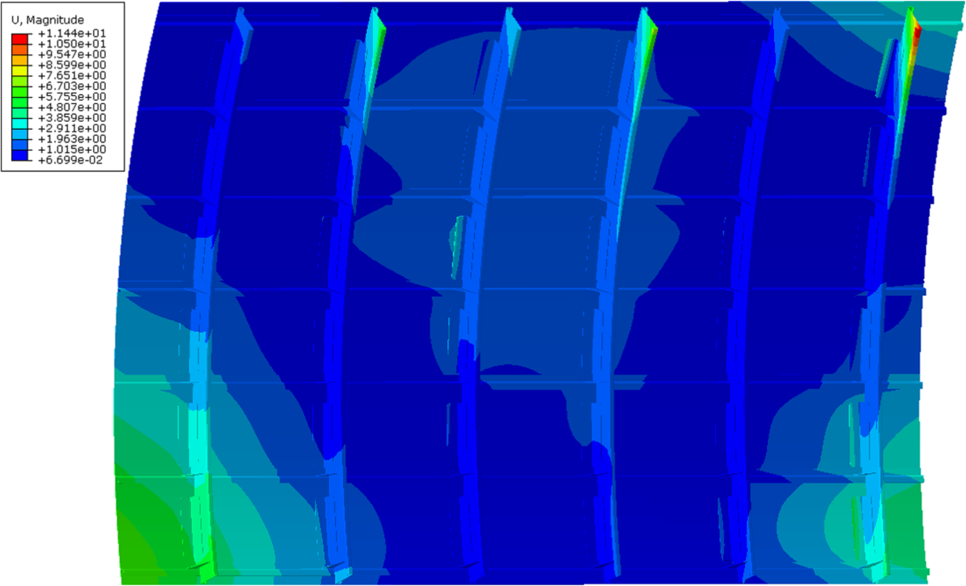
Variation contour of the panel corresponding to the worst case.
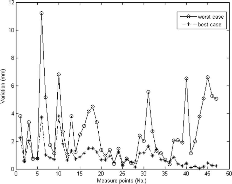
Comparison of the variations of the measurement points.
Conclusion
In this article, a flexible, continuous beam-based assembly model is established. Based on the analysis of the model, the traditional variation analysis process is simplified to a loading process of the forced assembly force.
Furthermore, an assembly location optimization method of variational and interchangeable parts is proposed. Case study on a fuselage panel is implemented. Comparison of the results corresponding to the best and worst case shows the reliability of the simplified method of the variation prediction and the necessity of the assembly location optimization.
Actually, assembly location optimization of the interchangeable parts transferred the problem from manufacturing process to the assembly process and then solved as far as possible. The method could improve the assembly quality or the production yield without increasing the tolerance requirements of the parts. This is important for the interchangeable sheet metal part manufactured independently and with a complex shape, as there is reduction in not only the technical difficulty but also the manufacturing cost.
In this article, only the case that the number of the parts equal to the number of the assembly positions is considered. Actually, the number of the parts may be larger than the positions. Then, the problem is to choose the parts to fit the positions and minimize the assembly variation, which can be solved by referring to the method.
Footnotes
Declaration of conflicting interests
The author(s) declared no potential conflicts of interest with respect to the research, authorship and/or publication of this article.
Funding
The author(s) disclosed receipt of the following financial support for the research, authorship, and/or publication of this article: This work is supported by National Natural Science Foundation of China (Grant no. 51305395), National Natural Science Foundation of China (Grant no. 51275463), Science Fund for Creative Research Groups of National Natural Science Foundation of China (No. 51221004) and the Fundamental Research Funds for the Central Universities 2014FZA4004.