
Abstract
Titanium alloys have emerged as a significant aerospace material due to the high strength, good corrosion resistance and high temperature resistance thereof, but such alloys also have poor machinability because of the unique properties. Rapid tool wear is a serious problem for titanium alloy machining, with tool wear resulting in different tool edges. In the present study, finite element technology was used to establish a 2D cutting numerical model, so as to investigate the influence of the different cutting edges caused by tool wear during the machining process of titanium alloy TC21. In the cutting model, four different types of tool edges, including sharp edge, round edge, chamfer edge and crater edge, were established to analyze the influence of different tool edges on the cutting process of TC21 alloy. Additionally, the material model, chip separation model, friction model and heat transfer model have been included in the established model. A series of cutting simulations based on the model were conducted, through which the chip morphology, cutting temperature, cutting force, surface morphology and residual stress under the different tool edges were analyzed. The simulation results were compared with the experimental results, and indicated that the tool edge is a significant factor in the machining process of TC21 alloy. A proper cutting edge can improve the cutting quality.
Keywords
Introduction
As a significant structural material in the aerospace industry, titanium alloys have numerous special properties, including low density, high strength, high temperature stability, and good corrosion resistance.1–3 However, due to the low thermal conductivity, high chemical activity and small elastic modulus, the machinability of titanium alloys is considerably poor, and the tool life is particularly low. As such, titanium alloys typically encounter difficulties when cutting materials, which limits the increases in cutting speed and productivity in the cutting of titanium alloys.4,5
A number of researchers have conducted studies to reveal the cutting mechanism and established useful technologies, so as to increase the machining efficiency of titanium alloys.6–12 Through the use of a high-speed imaging device, Cotterell and Byrne 6 investigated the morphology of shear band and serrated chip in the cutting of titanium alloy Ti6Al4V. With a micro-textured ball-end milling cutter, Yang et al. 7 investigated the stress field distribution under the conditions of anti-friction and anti-wear in the cutting of titanium alloys, and established the empirical models of cutting force and the contact area between the tool and the chip by means of the milling test. Huang et al. 8 analyzed the vibration reduction mechanism of high-speed milling for Ti6Al4V alloy under dry cutting environment conditions and surveyed the effect of high-speed cutting on the vibration and cutting force. Li et al. 9 analyzed the dynamic cutting angle, cutting parameters and cutting strain in the vibration assisted cutting of titanium alloy Ti6Al4V.
Although the machining level of titanium alloys is improving, further research on the cutting mechanism for titanium alloys is needed. The cutting process of titanium alloys is one that includes high cutting heat, high strain and high strain rate. With tool wear becoming the most serious problem of titanium alloy cutting, numerous studies have been conducted to analyze the wear mechanism and find methods to decrease the tool wear for extending the tool life.5,13–22 Pramanik et al. 13 analyzed the causes of chip formation and tool wear in the cutting of titanium alloy and confirmed that the main factors of tool wear include plastic deformation, thermal cracking, abrasion and diffusion. Biermann et al. 14 surveyed the cryogenic cutting process of two different titanium alloys and analyzed the different behavior and tool life in cutting processes under cryogenic conditions. For reducing tool wear, Zhou et al. 15 used an ultrasonic vibration method to assist in the turning of titanium alloy TC4, and confirmed that tool wear can be significantly reduced by ultrasonic vibration cutting. Nouari and Makich 16 analyzed the relationship between the workpiece microstructure and tool wear in the cutting of two different titanium alloys, and discussed the evolution of the microstructure with different cutting parameters. Jawaid et al. 17 investigated the wear mechanism when dry cutting titanium alloys, and found that tool wear can be obviously reduced by good honed edge and grain size.
With the recent progress of computer and software science, finite element technology has been extensively adopted in the cutting field, providing support for the study of chip formation, cutting temperature prediction, microstructure evolution, cutting force and residual stress.23–33 At present, finite element technology is generally regarded as an indispensable method for investigating the cutting mechanisms of titanium alloys.34–42 Hu et al. 34 established a 2D finite element model to explore the effect of the ultrasonic method on the ultra-precision cutting of Ti6Al4V alloy under different cutting conditions. Zhou et al. 35 adopted a new modified Johnson-Cook model in the cutting finite element model of Ti6Al4V alloy and compared the results with those of previous models using different materials. Thepsonthi and Özel 36 established a 2D elasto-viscoplastic cutting model To analyze the serrated chip in the micro-milling of Ti6Al4V alloy. Chen et al. 37 developed a constitutive model with a damage criterion in the simulation of high-speed cutting of Ti6Al4V alloy and simulated the cutting under different cutting speeds. By applying a displacement-based ductile failure criterion, Aydın and Köklü 38 established a 2D orthogonal finite element model to analyze the segmented chip formation of Ti6Al4V alloy.
However, there remains minimal understanding of the effect of different cutting edges caused by tool wear when cutting titanium alloys. Tool wear can change the geometrical shape of tool edges and affect the cutting process. In the present study, a 2D cutting model established by finite element technology was used when analyzing the cutting of one high strength titanium alloy TC21 with different tool edge patterns. Moreover, the effect of tool wear patterns on the chip morphology, cutting forces, cutting temperature, surface morphology and stress distribution of TC21 alloy was investigated in-depth. The simulated chip shape was also verified through a series of chip formation cutting experiments.
Experimental setup
The type of titanium alloy was TC21 in the present study. Because of the high strength thereof, TC21 alloy is mainly used in areas where high strength is required for aerospace parts. The workblank of TC21 alloy is forged at a temperature of 989°C and the forging process involves two stages. During each forging process, the deformation rate is 50%. The air cooling will be used to cool the workblank after forging. Subsequently, the workblank will be heat treated for 2 h at 900°C and 2 h at 590°C, respectively. The material properties of TC21 alloy are listed in Table 1.
Physical properties of TC21 alloy.
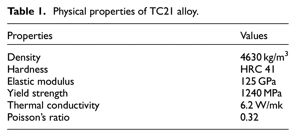
TC21 alloy has a higher strength compared to other titanium alloys, and tools are easier to wear during cutting processing, which will lead to different tool edges. To investigate the effect of different cutting edges on the machining process of TC21 alloy, tools with four different edges were made and used in the cutting experiments, so as to reveal the effect on the chip formation. The detailed shape and dimension of four different tool edges are shown in Figure 1.
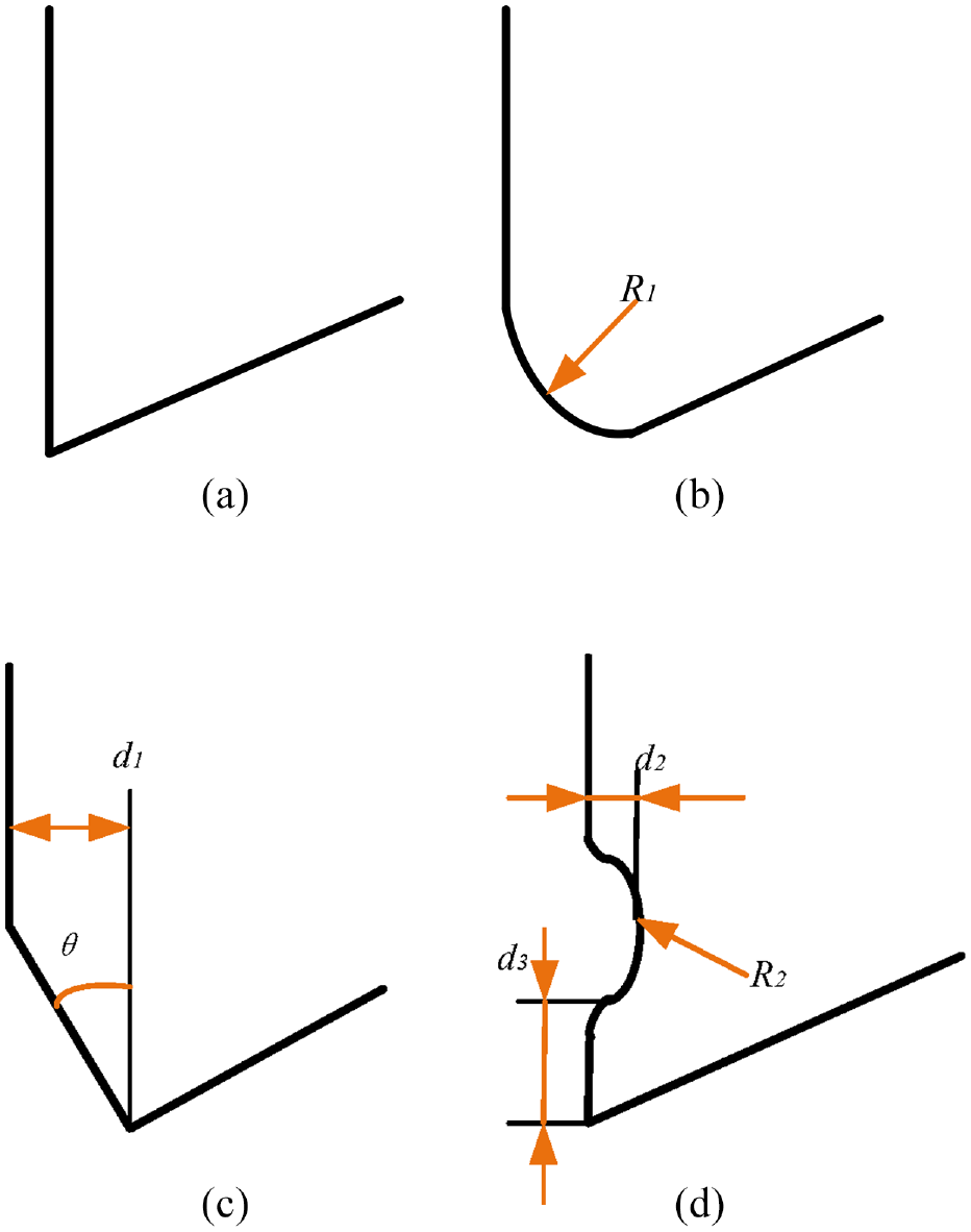
Schematic of four different tool edges: (a) sharp edge, (b) round edge (R1 = 0.5 mm), (c) chamfer edge (d1 = 0.2 mm, θ = 20°), and (d) Crater edge (d2 = 0.1 mm, d3 = 0.2 mm, R2 = 0.5 mm).
Comparison experiments of the chip morphology of TC21 alloy were conducted in the numerical control machine and the experiment setup is shown in Figure 2. The cutting parameters are shown in Table 2.
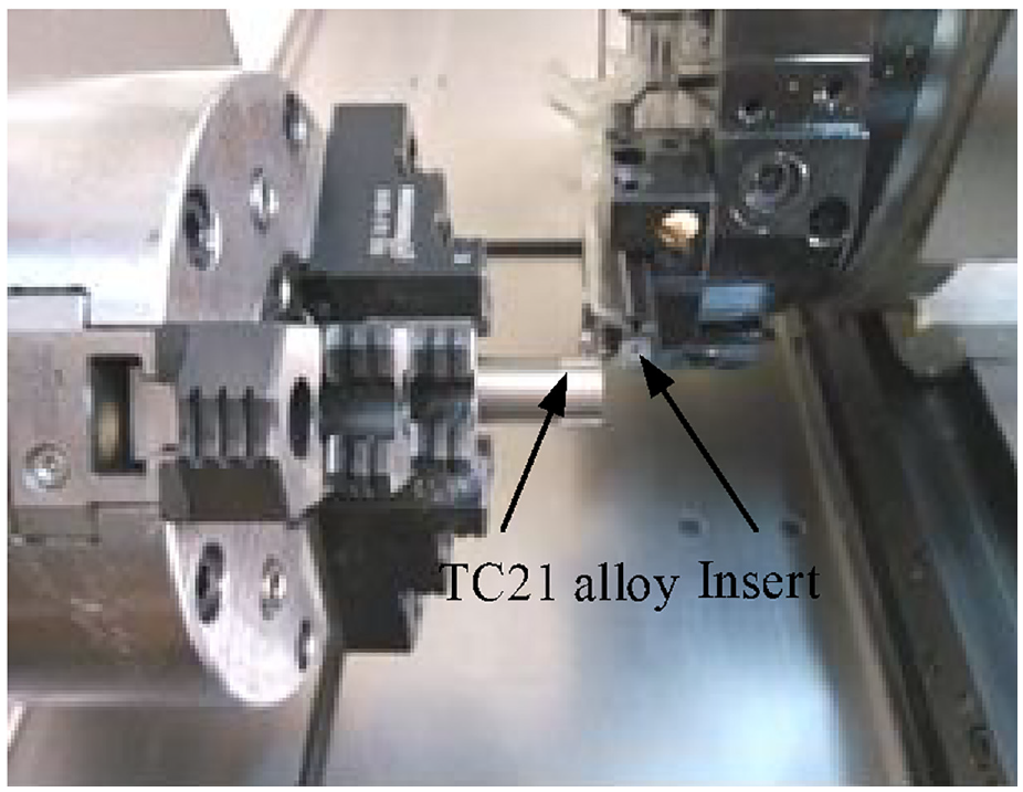
Cutting experiment of TC21 alloy.
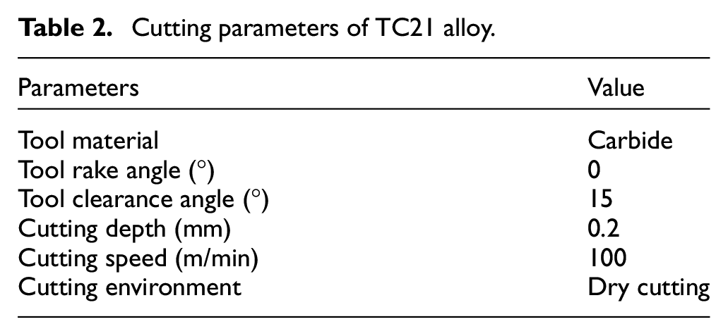
Cutting parameters of TC21 alloy.
Finite element cutting model
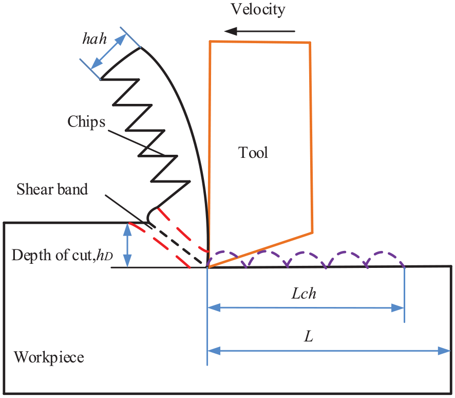
The 2D cutting model is useful for exploring the cutting mechanism and investigating the cutting behaviors of metals, and thus, has been largely applied in research on metal cutting. The motion of the tool and the workpiece, the material deformation and the chip forming process are clearly shown in the orthogonal cutting schematic for TC21 alloy, as shown in Figure 3.
Schematic of 2D cutting model.
During the cutting process, chip formation refers to the deformation and separation process of the cutting layer material. When the workpiece is squeezed by the tool, the cutting layer material will undergo elastic deformation. When the stress reaches the yield strength of the material, plastic deformation and slip occur. The cutting layer material deforms to form the chip, the thickness increases, the length decreases and the width basically stays the same. The degree of deformation of the cutting layer material can be expressed by the deformation coefficient. The deformation coefficient can take three forms, including the coefficient of thickness deformation
An orthogonal model of the cutting simulation for TC21 alloy was built through the software ABAQUS 2020, as shown in Figure 4. The mesh in the cutting layer of the workpiece was refined to improve the calculation precision. During the cutting simulation, the workpiece remained stationary and a speed constraint was applied to the tool. Because of the lower thermal conductivity, the adiabatic module is more feasible for solving the mechanical problems of TC21 alloy, and was used in the simulation. The detailed parameters of the model are listed in Table 3. The cutting parameters of the simulation were the same as those of the cutting experiments. The mesh type was quadrilateral grid and the mesh size of the workpiece was 2 µm × 2 µm. The average calculation time of each set of parameters was about 50 h.
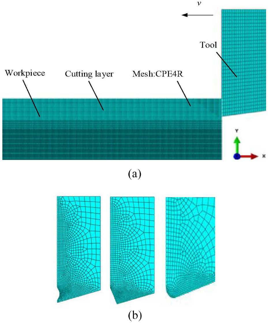
The cutting model of titanium alloy under the different tool edges: (a) finite element model for TC21 alloy and (b) tool model with different tool edges.
Parameters of finite element model.
The material constitutive model is a mathematical equation of strength-stress-strain-time relationship, which is considerably significant for the cutting simulation of metal materials. The Johnson-Cook material model 43 is a combination of strain, strain rate and temperature, which can accurately express and reflect the phenomenon of high heat and high strain during the metal cutting, and thus, was also used in the simulation of TC21 alloy. The stress-strain relationship in the Johnson-Cook material model can be expressed by equation (4).
where
Additionally, when the Johnson-Cook constitutive model is adopted in cutting model, the corresponding Johnson-Cook damage criterion needs to be used for realizing the separation of the workpiece and the chip. 44 In the damage criterion, the damage occurs when the equivalent plastic-strain is equal to a critical point. The Johnson-Cook damage criterion is expressed by equation (5).
In equation (5), D1–D5 are the damage coefficients; p is the hydrostatic pressure; q is the Mises stress;
During the cutting process of metals, the friction action of the tool and the workpiece is relatively complicated, in that friction directly affects the life and performance of the tool. In metal cutting, especially in the machining of high strength workpiece materials, the pressure and temperature generated by friction are the main causes of tool failure. The contact area between chip and tool includes two regions, a sliding region and a sticking region. 45 The sliding region complies with the Coulomb friction law, while the critical friction stress is equal to the shear stress in the sticking region. The frictional coefficient in the cutting simulation was set as 0.31 and the value of the friction coefficient was obtained through the material friction experiments.
During metal cutting, in addition to the heat generated by friction, the energy consumed by the elastic and plastic deformation of metals under the cutting action of tool is also a significant source of cutting heat. During cutting, the cutting heat mainly comes from the plastic deformation and the friction between tool and chip. The plastic deformation of materials during the cutting process occurs mainly in the primary shear zone and most of the deformation energy will be converted into heat. During the cutting simulation of TC21 alloy, 90% of the deformation energy was set to be converted to heat.
Results and discussions
Stress state and chip morphology in simulation
During metal cutting, the chip formation process is relatively complicated. The shape of the cutting edge has a significant impact on the formation and flow of the chip. Under different cutting parameters, the chip will exhibit different shapes because the chip formation mechanism is different. Figure 5 shows the flow of the workpiece material when the tool is first cut. The shear band can be clearly observed in Figure 5(a) to (c), in which the shear band was formed from the point of contact between the workpiece and the tool tip. However, the shear band in Figure 5(d) was not obvious, and a significant distortion that occurred in the area where the chip contacted with the tool crater area can be observed. In addition, an observation can be made that the workpiece was separated into a chip surface and a machined surface at the position of the tool tip, as shown in Figure 5(a), (c), and (d). However, as shown in Figure 5(b), the workpiece material started to separate into a chip surface and a machined surface at the middle of the arc at the tool edge.
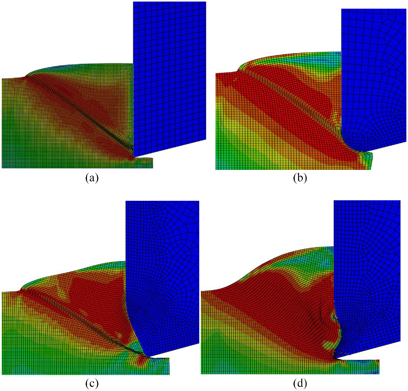
Material flow and formation of shear band under the different tool edges: (a) sharp edge, (b) round edge, (c) chamfer edge, and (d) crater edge.
As shown in Figure 6, the chip morphology and stress distribution during the cutting simulation of TC21 alloy under different tool edges were obtained. Figure 6 shows that the chips were serrated when cutting TC21 alloy with the sharp edge, chamfer edge and round edge, while the serrated chip was inconspicuous with the crater tool edge. At the same time, the thickness of the chip with the crater and chamfer tool edges obviously increased. In addition, the stress of the shear band with the sharp edge was the lowest and the cutting stress of the shear band with the chamfer edge was the highest. The simulation results show that the crater edge hindered the chip outflow and delayed the slip of the material along the shear band.
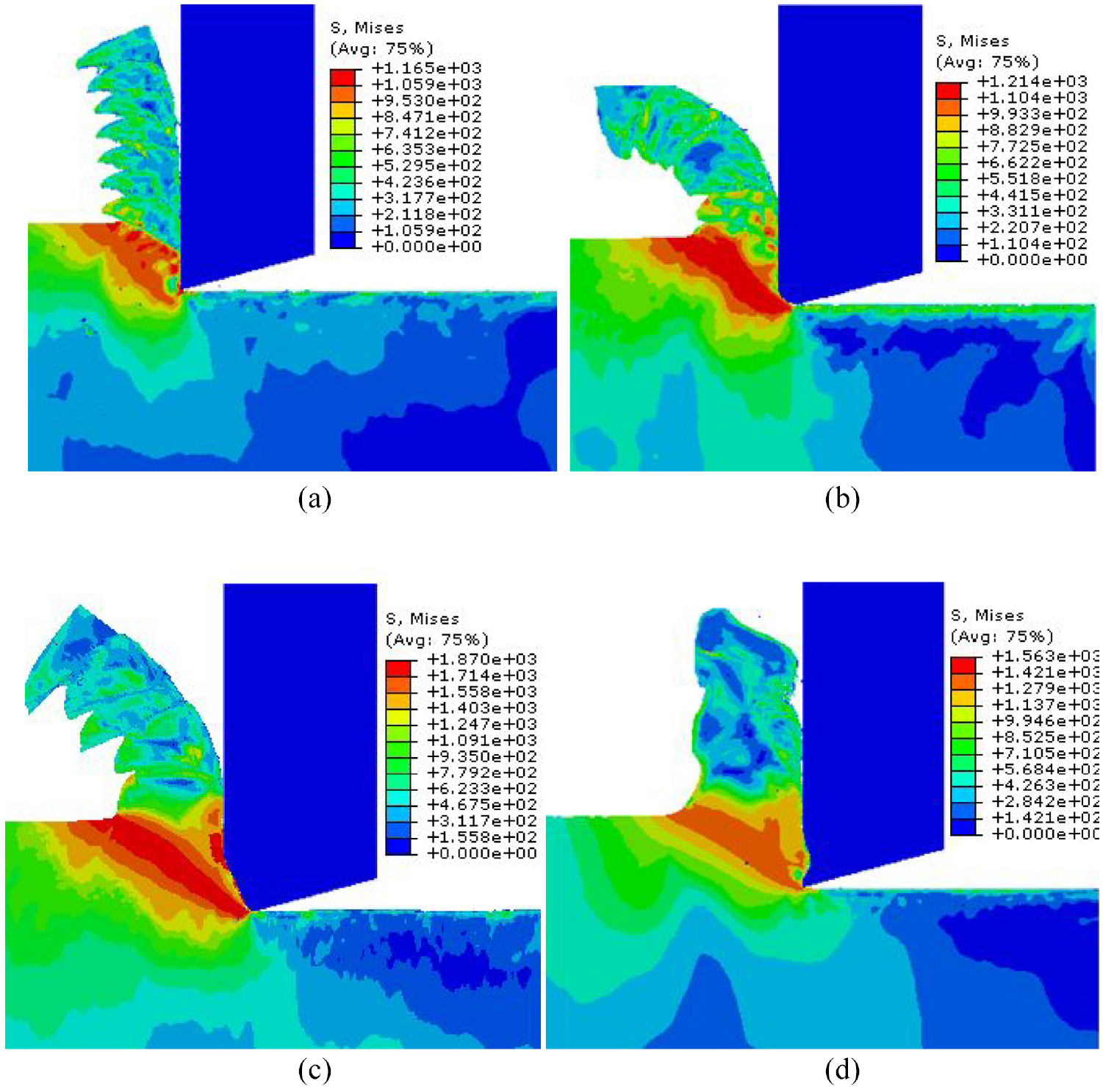
Chip formation and stress distribution with the different tool edges: (a) sharp edge, (b) round edge, (c) chamfer edge, and (d) crater edge.
Impact of tool edges on cutting temperature
In the cutting process, the deformation energy consumed during the elastic and plastic deformation of the workpiece material is the main source of cutting heat. Additionally, the friction actions between the chip and the rake tool surface, and the workpiece and the clearance tool face also produce a large amount of heat. Thus, there are three heating areas in cutting, namely the shear band, contact area of the chip and rake tool surface, the clearance tool surface and the machined surface. When cutting, the workpiece, the chip and the tool absorb the cutting heat and make the temperature rise, is the temperature not only depends on the heat generated in cutting, but is also related to the heat conduction.
However, because of the ultra-low thermal conductivity of TC21 alloy, most of the cutting heat generated by deformation cannot be absorbed during the cutting and is mainly concentrated in the shear zone. Therefore, adiabatic analysis was adopted in the finite element analysis, and the temperature only existed in the region where the deformation occurred.
Figure 7 shows the cutting temperature with the different tool edges of TC21 alloy obtained through the cutting simulation. The area with the highest cutting temperature on the workpiece was at the shear zone of the workpiece with the sharp, round and chamfer tool edges, while the zone with the highest temperature on the workpiece with the crater tool edge was at the contact zone with the tool rake face. Moreover, the temperature of the shear band was the highest with the chamfer tool edge.
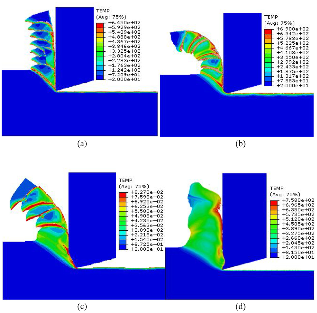
Temperature distribution with the different tool edges: (a) sharp edge, (b) round edge, (c) chamfer edge, and (d) crater edge.
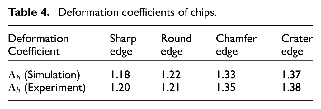
Figure 8 shows the chip shapes obtained by cutting experiments with four kinds of wear tool edges, which were considerably similar to the chip shapes obtained in the cutting simulation. Table 4 shows the deformation coefficients of the chips, which confirm that the chip deformation coefficients obtained by the chamfer and crater edges were larger than those obtained by the other two tool edges.
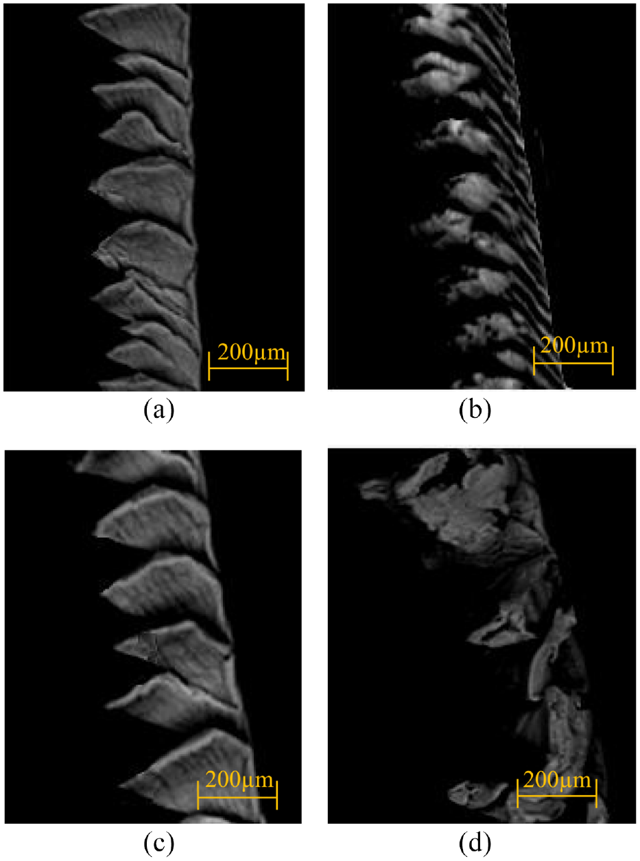
Chip morphology of tests with the different tool edges: (a) sharp edge, (b) round edge, (c) chamfer edge, and(d) crater edge.
Deformation coefficients of chips.
Influence of cutting edges on cutting force, surface morphology and residual stress
The cutting force is the resistance of the tool to the material and is affected by many factors. From the perspective of tool geometry, the cutting force is mainly affected by the rake angle, rear angle and tool tip shape. Figure 9 shows the cutting force curves obtained by the cutting simulation of TC21 alloy. The cutting force fluctuated with the formation of the serrated chip and the fluctuation amplitude of the cutting force was more serious with the chamfer and crater tool edges. Further, the cutting forces obtained by using the sharp and round tool edges were also smaller than those obtained by the other two tool edges.
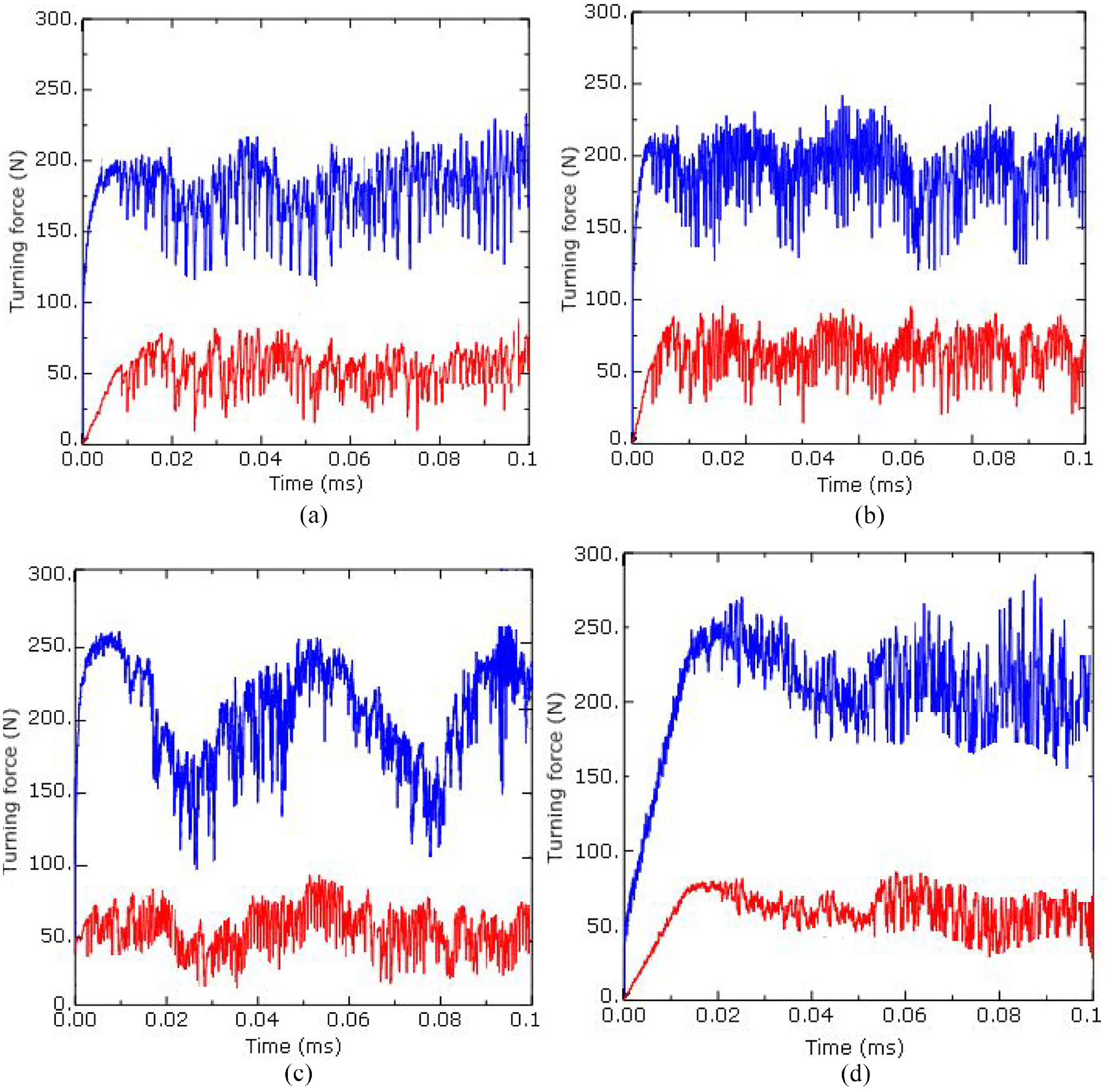
Cutting forces with the different tool edges in simulation: (a) sharp edge, (b) round edge, (c) chamfer edge, and (d) crater edge.
Different tool edges will not only affect the chip formation, but also affect the surface morphology and residual stress of the machined surface. Figure 10 shows the machined surfaces obtained with different tool edges. The quality of the machined surface obtained with the round edge was the lowest, and defects such as burrs can be clearly seen. Such findings could be attributed to the excessive tool fillet rendering difficulties in the separation of the chip from the workpiece. At the same time, as shown in Figure 10(a), (c), and (d), the workpiece material at the tool tip was easy to separate because of the sharp tool tip. However, as shown in Figure 10(b), the material at the fillet of the tool tip was divided into two parts due to the large fillet value, with one part forming the chip, and the other part being crushed into the machined surface by the tool. Therefore, the residual stress value in the Figure 10(b) was the largest. The results confirm that the sharpness of the tool edge is considerably significant for chip formation and surface quality.
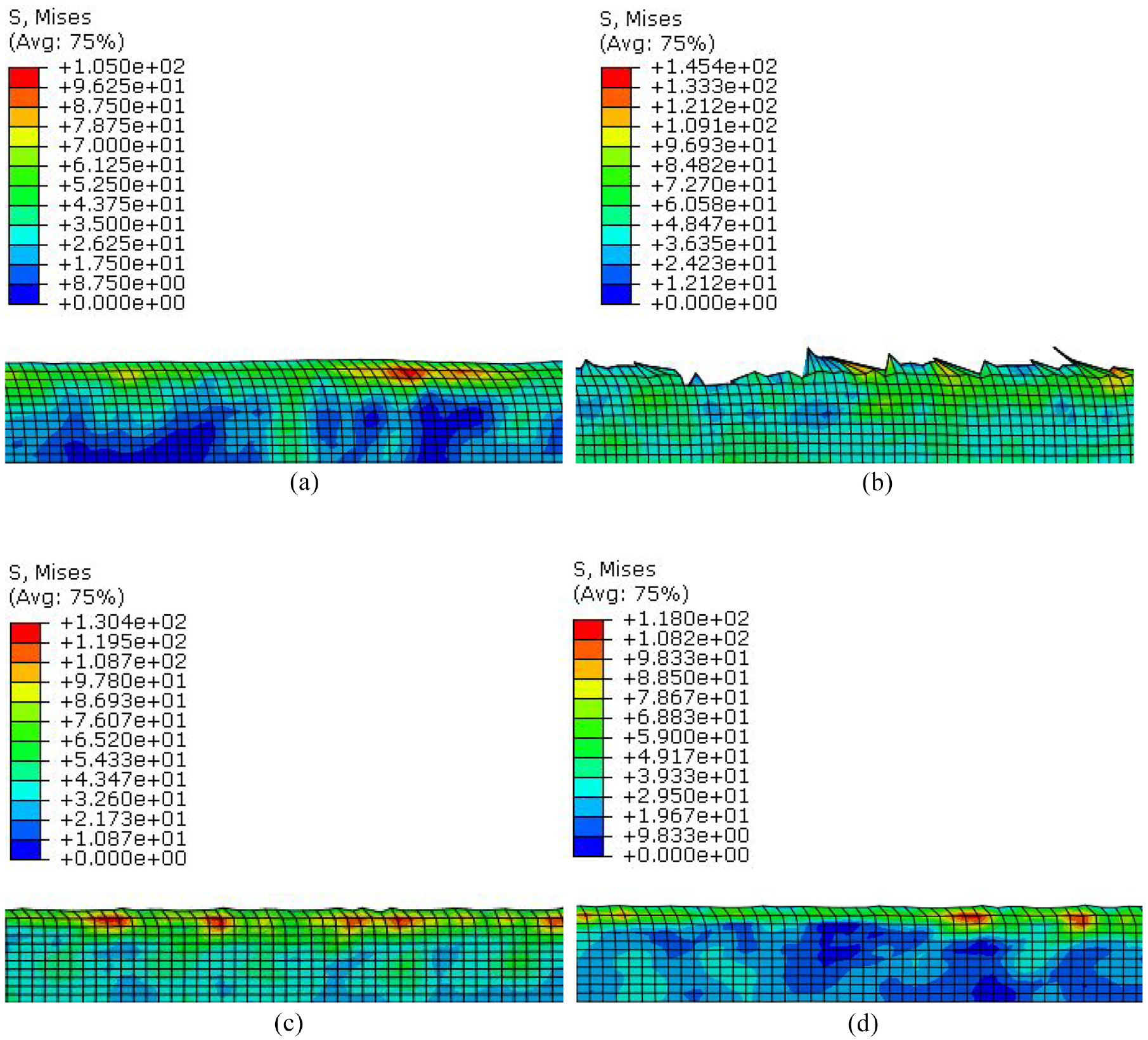
Surface morphology and residual stress under the four tool edges: (a) sharp edge, (b) round edge, (c) chamfer edge, and (d) crater edge.
Conclusions
In order to investigate the effect of various cutting edges caused by tool wear in the machining process of titanium alloys, finite element technology was adopted to reveal the cutting mechanisms. In the present study, an orthogonal finite element model was established. Through the simulation, the stress distribution, chip formation, cutting force, surface morphology, cutting temperature and residual stress were obtained. The influences of the different cutting edges on the cutting process of TC21 alloy were investigated through the comparison analysis. Additionally, a number of chip formation tests for TC21 alloy under the four different tool edges were conducted. The chips in the simulation exhibited good consistency with the chips obtained in the cutting tests. The results of the present study confirm that cutting edges have a significant influence on the cutting of TC21 alloy, especially in terms of the chip shape. At the same time, the present research shows that the change of the tool edge caused by wear altered the flow of metal in the cutting layer, which in turn altered the shape of the chip and the corresponding amount of cutting.
Footnotes
Declaration of conflicting interests
The author(s) declared no potential conflicts of interest with respect to the research, authorship, and/or publication of this article.
Funding
The author(s) disclosed receipt of the following financial support for the research, authorship, and/or publication of this article: This research has been supported partly by the Ningbo Enrichment Project of China (Grant no. 2017C10013) and Natural Science Foundation of Ningbo, China (Grant No. 2021J164).