
Abstract
Bone drilling is one of the steps in a typical surgical operation that is performed around the world for reconstruction and repair of the fractured bone. During the last decade, various techniques, such as two-step drilling, ultrasonic-assisted bone drilling and laser drilling, have been introduced to control the level of forces and torque during bone drilling. In this research, rotary ultrasonic bone drilling has been successfully attempted to minimize the forces and torque during bone drilling. The drilling experiments were planned and carried out on pig bones using the design of experiments (response surface methodology). Analysis of variance was carried out to find the effect of process factors such as rotational speed, feed rate, drill diameter and ultrasonic vibrational amplitude on the force and torque. Statistical models were developed for the force and torque with 95% confidential interval, and confirmation experiments have been carried out to validate the models. Microcracks developed during drilling process were characterized by scanning electron microscopy. The results revealed that rotary ultrasonic bone drilling process offered a lower force and torque making it a potential process for bone drilling in orthopedic surgery.
Introduction
Nowadays, millions of surgeries are performed around the world in orthopedics, dental, neurosurgery, plastics and reconstructive, craniomaxillofacial, ear, nose, throat and so on. Various bone-cutting techniques, such as drilling, sawing, boring, grooving, grafting and shearing, are available in the medical field. Out of these, drilling of the bone is the most common surgical operation in the medical field.
Bone fracture is a universal phenomenon which may occur due to accident or age factor. Reconstruction and repair of these fractured parts are done by fixing them with the help of screws, wires, plates, locking bolts etc. Owing to these fixing aids into the bones, pilot holes are required during the surgery. These pilot holes are done with the help of the drilling technique, where the traumatologist applies axial force on the drilling tool for penetrating it through the bone. This process involves drill force and torque during bone drilling. High cutting force and torque lead to problems such as delamination of the bone, 1 increased crack levels, 2 poor hole accuracy, stuck of drill bit or even drill breakage, 3 thermal necrosis, 4 osteosynthesis and so on. It is reported that the implant failure rate for lower leg due to osteosynthesis is around 2.1%–7.1%.5–7 Hence, there is always a necessity to minimize the magnitude of drilling force and torque during bone drilling process.
Various process parameters have been reported in the literature, 8 which influence the bone drilling process such as drill diameter, feed rate, rotation speed of the tool, drilling depth, drill geometry, drill bit material and irrigation method. Over the last few decades, limited research has been conducted to control the force and torque during bone drilling process, and the details of which have been summarized in the following.
Bachus et al. 4 conducted an in-vitro study on the cortical bone. They investigated the effect of applied force on the temperature as well as time duration during drilling. It was reported that the temperature and time duration are strongly influenced by the applied force. Similar kinds of conclusions were made by Brisman. 9
MacAvelia et al. 10 reported that force and torque reduced significantly with the increase in the rotational speed (1000, 1250 and 1500 r/min) at a constant feed rate of 120 mm/min with 3.2 mm drill bit, for a human femur and artificial femur. Range of drilling forces for human femur with respect to given speed was found to be 198.4 ± 14.2, 180.6 ± 14.0 and 176.3 ± 11.2 N and for artificial femur 87.2 ± 19.3, 82.2 ± 11.2 and 75.7 ± 8.8 N. Similarly, the torques for human femur were 186.3 ± 16.9, 157.8 ± 16.1 and 140.2 ± 16.4 N mm and for artificial femurs 67.2 ± 8.4, 61.0 ± 2.9 and 53.3 ± 2.9 N mm. They concluded that rotational speed showed a less significant effect on the force and torque while drilling on the artificial femur as compared to the human femur.
Soriano et al. 11 conducted bone drilling study on bovine cortical bone. They investigated the effect of bone drilling input parameters on the force, torque and temperature, with surgical and industrial drill bits. The results showed that force and torque increased with increase in the feed rate and decreased with the increase in the rotational speed with 5.3 mm drill diameter. Their experimental results also concluded that maximum and minimum forces were 50 N (with 50 r/min speed and 0.2 mm feed rate) and 10 N (500 r/min speed and 0.05 mm feed rate).
Tuijthof et al. 12 performed bone drilling on pig and goat bone with different types of drill geometries and drill bit diameters of 3 and 3.2 mm. They investigated the effect of different types of drill bit geometries on the force and torque by varying the feed rate. It was found that cutting force during bone drilling process was highly influenced by different drill geometries as well as feed rate. In their investigation, the range of the force was 10–100 N.
Soriano et al. 13 conducted drilling experiments with eight different types of drill bit geometries by varying bone drilling parameters. It was observed that force and torque could be reduced to about 60% and 50%, respectively, when a drill bit with 18° rake angle and 0.1 mm margin thickness was used.
Sui et al. 14 proposed a mechanistic model to predict force and torque. The developed model was validated on the bovine bone by varying drilling speeds and feed rates (500 and 1500 r/min, 0.04 and 0.08 mm/rev) with constant drill diameter of 4.2 mm. Forces predicted were in agreement with the findings of the experiments, whereas torque did not show such agreement.
Wang et al. 15 conducted studies to find out the influence of spindle speed, drill diameter and feed rate during the drilling of fresh bovine bones on the force and torque. Experimental study showed that force and torque could be minimized with a higher spindle speed and low feed rate with 2.5 mm drill diameter. It was also observed that the automatic drill could save 30%–60% drilling time as compared to manual drilling. Their experimental results showed that a maximum force of 165 N at 2500 r/min with 2.5 mm drill bit diameter and 10 mm/min feed rate and a minimum force of 65 N at 500 r/min with 2.5 mm drill diameter and 50 mm/min feed rate were obtained.
Recently, Lughmani et al. 16 investigated the effect of feed rate and spindle speed on force and torque experimentally and theoretically with 2.5 mm drill bit on bovine cortical bone. It was found that force and torque ranged from 25 to 75 N and from 1.2 to 1.6 N cm, respectively. Their study concluded that force and torque reduced with reduction in feed rate and increase in rotational speed.
Alam et al. 17 compared the two drilling methods that is conventional drilling (CD) and ultrasonic-assisted drilling (UAD) and found that using UAD, force and torque could be reduced. Experiments were performed with a constant drill diameter of 4 mm while varying the feed rate and spindle speed. They concluded that force and torque could be reduced with increase in the rotational speed and decrease in the feed rate. Similar findings were reported by Shakouri et al., 18 but in their study, the feed rate was kept too high. Drilling with a higher feed rate produced cracks and delamination in the bones.
Most of the investigations of bone drilling were performed by the CD method.1,4,9–16 Over the last few years, researchers tried to introduce new techniques such as ultrasonic-assisted bone drilling,17,18 laser bone drilling 19 and water jet bone drilling. 20 The main problem with laser bone drilling is the burning of soft tissues near the drilled hole. Handling the equipment and controlling the process parameters are the major problems in water jet bone drilling. Force and torque could be reduced with UAD, but still there is a need to minimize the force and torque during bone drilling process to minimize or eliminate problems such as microcracks, thermal necrosis, delamination of bone and hole inaccuracy.
This study is focused on the rotary ultrasonic bone drilling (RUBD) with a hollow tool, coated with diamond abrasive particles. This is similar to the rotary ultrasonic machining (RUM) process, in which ultrasonic vibrations are given to the hollow abrasive coated tool, with a frequency of 20 kHz or more. The ultrasonically excited tool is rotated by the computer numerical control (CNC) milling spindle and is fed downward, perpendicular to the workpiece. Material is removed from the workpiece due to direct cutting action of bonded abrasive particles on the tool.
In the literature,21–23 it is reported that RUM has various advantages over the CD, such as lower cutting force and torque, less surface damage, minimum tool wear rate and lower surface roughness. RUM has been widely used to drill holes in carbon fiber–reinforced polymer (CFRP), 22 titanium alloy, 24 ceramic and its composite. 25 Due to the various advantages and benefits of RUM, an attempt has been made to drill bone with this process. The RUBD drilling is expected to minimize force and torque ensuring better hole quality with minimum cracks.
Details of experimental setup and bone specimen
This section deals with the design and fabrication of RUBD setup, bone drilling tool and specimen preparation.
Design and fabrication of RUBD setup and bone drilling tool
In order to perform the RUBD, an experimental setup and diamond abrasive coated hollow tools were designed and fabricated. Figure 1(a) shows the schematic diagram of rotary ultrasonic tool assembly.
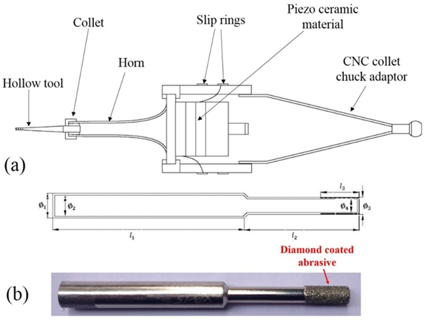
(a) Schematic illustration of rotary ultrasonic tool assembly and (b) CAD model and image of the diamond-coated abrasive tool.
In this system, an ultrasonic transducer of 800 W was connected to the tool holder and external housing. Drilling tool was held on to the ultrasonic horn with the help of tool holder. Two slip rings were also attached around the housing. Carbon brushes were connected to the slip rings that were used to provide voltage signals to the ultrasonic horn. An ultrasonic power supply of 220 V and 20 kHz frequency was used to actuate the transducer, and due to this, it is pulsated axially with 20 kHz frequency. Hollow tools were designed and fabricated with different inner and outer diameters as shown in Figure 1(b). Wall thickness of 0.8 mm was kept constant for all the tools. Diamond abrasive particles of mesh size of 80–100 were coated on the hollow tools by electroplating.
The entire assembly was clamped in CNC vertical milling chuck with the help of CNC tool holder, as shown in Figure 2. All the experiments were performed on the same setup. The system has two controllers: one is used to control the feed rate, rotational speed and table motion and the other controller is used to provide the ultrasonic vibration on the tool as well as to control the vibrational amplitude. Due to the unsymmetrical nature of the bone, a special type of bone fixture was designed and fabricated which was used to hold the bone and secure drilling. A six-axis dynamometer was calibrated and used to measure the value of forces and torque. Typical force versus time and torque versus time graphs are shown in Figure 3. The workpiece was placed perpendicular to the tool direction and the vibrating tool moved in upward and downward directions with the provided feed.
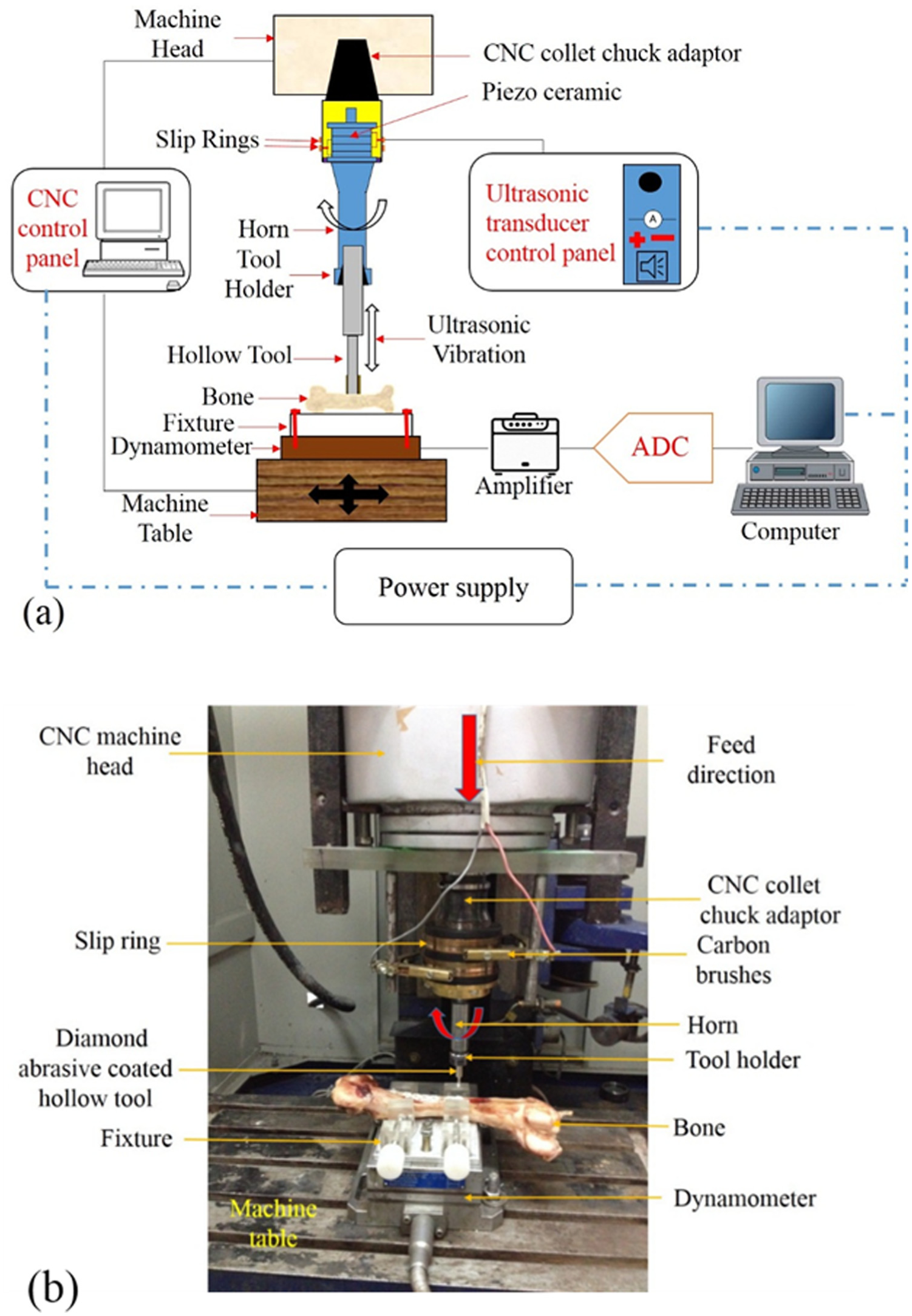
(a) Schematic diagram of RUBD experimental setup and (b) experimental setup for RUBD process.
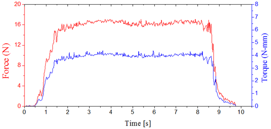
Measured value of force and torque with respect to time using the dynamometer. Rotational speed = 1500 r/min, feed rate = 30 mm/min, drill diameter = 3.5 mm and amplitude = 12 µm.
Specimen details
Fresh pig femur bones were used as workpiece for drilling holes in this in-vitro study. Experiments were performed on the mid-diaphysis section of the bone. Fresh pig bones were chosen because these are similar to the human bone.26,27 Fresh bones were obtained immediately after the slaughter from a local butcher shop. Experiments were performed on the bones of male pigs that were around 10-month old and average weight of 95–100 kg. Length of the central part of the femur bone was approximately 75–80 mm with cortical thickness of 4–5 mm. Experiments were performed within 2 h of the slaughter to retain its mechanical, physical and thermal properties with the soft thin periosteum layer, as shown in Figure 4. The study was conducted at room temperature without any irrigation technique.
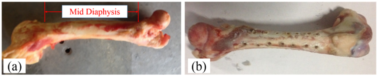
Fresh pig bone specimen: (a) before experiments and (b) after experiments.
Experimentation details
This section deals with the design of experiments (DOE) and selection of process parameters.
Design of experiments
Experiments in this in-vitro study were designed to evaluate the effect of process parameters of RUBD on the process response that is force and torque. DOE is one of the critical steps in the experimental studies. Taguchi method or orthogonal array (OA) and central composite design (CCD) or response surface methodology (RSM) techniques are widely used to reduce the number of experiments and to predict the behavior of input process parameters on the output response. Taguchi method is used to predict first-order effects, whereas CCD or RSM techniques are used to predict the second-order behavior of the response for a broader range of process factors. 28 Therefore, RSM design technique was chosen to obtain the second-order statistical model of force and torque for bone drilling using RUBD process.
Selection of process parameters
In this study, rotational speed, feed rate, drill tool outer diameter with constant wall thickness and vibrational amplitude were selected as the process factors. Table 1 lists the levels, ranges and the uncoded values of the input process parameters selected in the study.
Process factor and range.
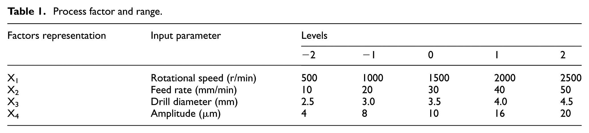
The range of rotational speed was selected on the basis of pilot study and the literature review. It was observed from the pilot study that no significant change in force and torque occurred with more than 2500 r/min. The lower value was selected as 500 r/min because it was observed that below this value drilling forces were high.
Lower and upper values of feed rate were chosen in the range of 10–50 mm/min. It was observed from the pilot study that above the upper value, delamination of the bone occurred and it also led to more cracks on the drilled surface. Therefore, 50 mm/min was selected as the upper value. Lower limit of 10 mm/min was selected as further decrease in the feed rate, resulted in the long drilling time.
In orthopedic surgery, the diameter range of holes remains between 2.5 and 4.5 mm. Therefore, in this study, tool diameter was selected in this range.
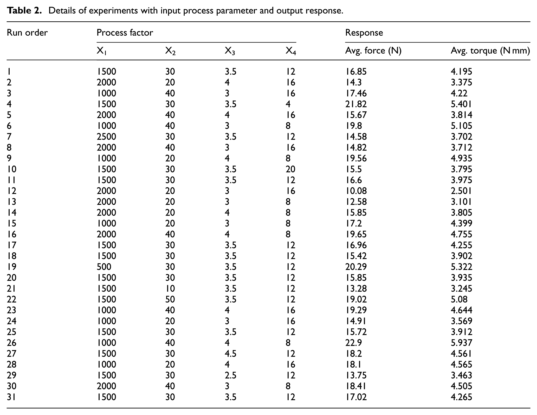
Range of vibrational amplitude was decided on the basis of the capabilities of the developed setup. The designed RUBD setup worked on minimum value of 4 µm, so the lower value of amplitude was selected as 4 µm. Above 20 µm amplitude, it was found that the values of force and torque were high, so 20 µm was selected as the upper value. The experiments were conducted in the sequence given in Table 2, along with the corresponding values of obtained force and torque.
Details of experiments with input process parameter and output response.
Results and discussions
The analysis of the data represented in Table 2 was carried out as per the standard procedure suggested by RSM method. In order to find out the process parameters that are significant in affecting the force and torque, an analysis of variance (ANOVA) has been performed. The details of the data analysis have been presented in the following.
Statistical modeling of force and torque
General second-order models were obtained by the regression analysis for the force and the torque in RUBD. The force and torque values obtained from the RUBD process as listed in Table 2 have been analyzed by the ANOVA. Initially, ANOVA was performed with all the significant as well as insignificant terms. The proposed models of force and torque were complex and had too many insignificant terms. Therefore, these models were improved and modified by neglecting all the terms that have an insignificant influence on the force and torque. The terms having their p value more than 0.05 are rejected.
The regression analyses were again carried out and adequacy of the modified models was tested. The new models for force and torque were obtained as represented by equations (1) and (2) and the corresponding pooled ANOVA tables are presented in Tables 3 and 4, respectively
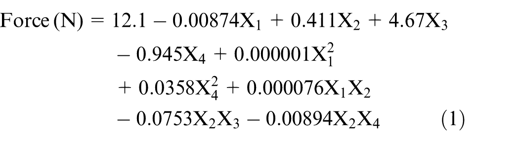
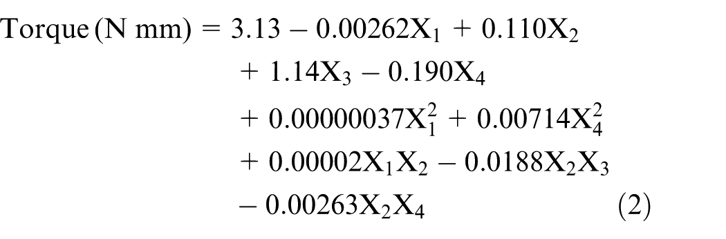
where
Pooled ANOVA for the forces with respect to equation (1).
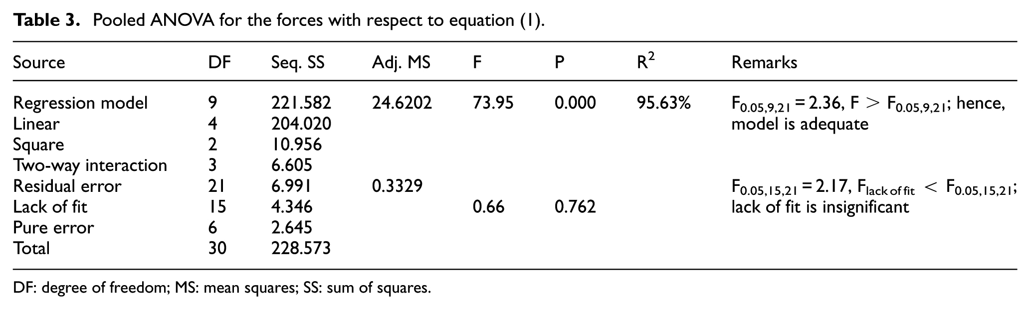
DF: degree of freedom; MS: mean squares; SS: sum of squares.
Pooled ANOVA for the torque with respect to equation (2).
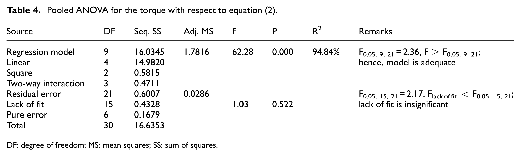
DF: degree of freedom; MS: mean squares; SS: sum of squares.
It was seen from the pooled ANOVA Tables 3 and 4 that the F ratios for the force and torque models were 73.95 and 62.28, respectively, which were higher than the tabulated F value (F0.05, 9, 21 = 2.36) and lack of fit of these models was also insignificant. The values of R2 for force and torque were 95.63% and 94.84%, respectively. Hence, these models were found to be adequate with 95% confidence interval. Therefore, equations (1) and (2) may be considered as predicted models for the force and torque of RUBD process in the range of process factors used for experimentation.
Precision of the proposed models
Error range of the proposed models was calculated due to the occurrence of some random errors during the experiments. Precisions of these models were estimated and calculated by equation (3)
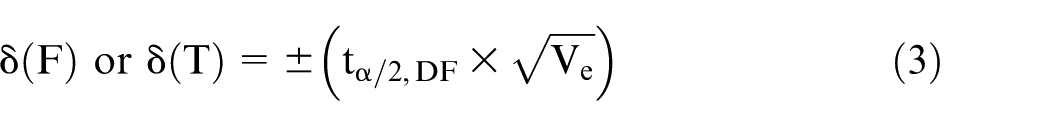
Here, δ(F) and δ(T) define the error range of the proposed models for force and torque, respectively; t is the statistical value of the t distribution; α is the level of confidence interval (i.e. 0.05 at 95% confidence level); DF is the total degree of freedom of the model; Ve is the error value of the variance of predicted models with respect to Tables 3 and 4. Predicted range of error due to the variance is ±1.178 N and ±0.345 N mm for force and torque, respectively.
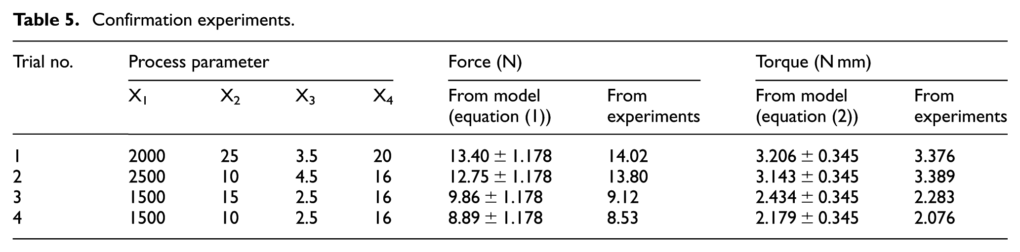
Four confirmation experiments were conducted for validation of the predicted models. The values of the process parameters for the confirmation experiments and the output responses (force and torque) are presented in Table 5. It can be observed from Table 5 that the experimental values of responses lie within the range as predicted by the developed statistical models for the force and torque, respectively.
Confirmation experiments.
Effect of process parameters
The main effect plot and the percentage contribution of the process factors are shown in Figures 5 and 6 for the force and torque, respectively. The obtained trends of main effects have been explained in the following.
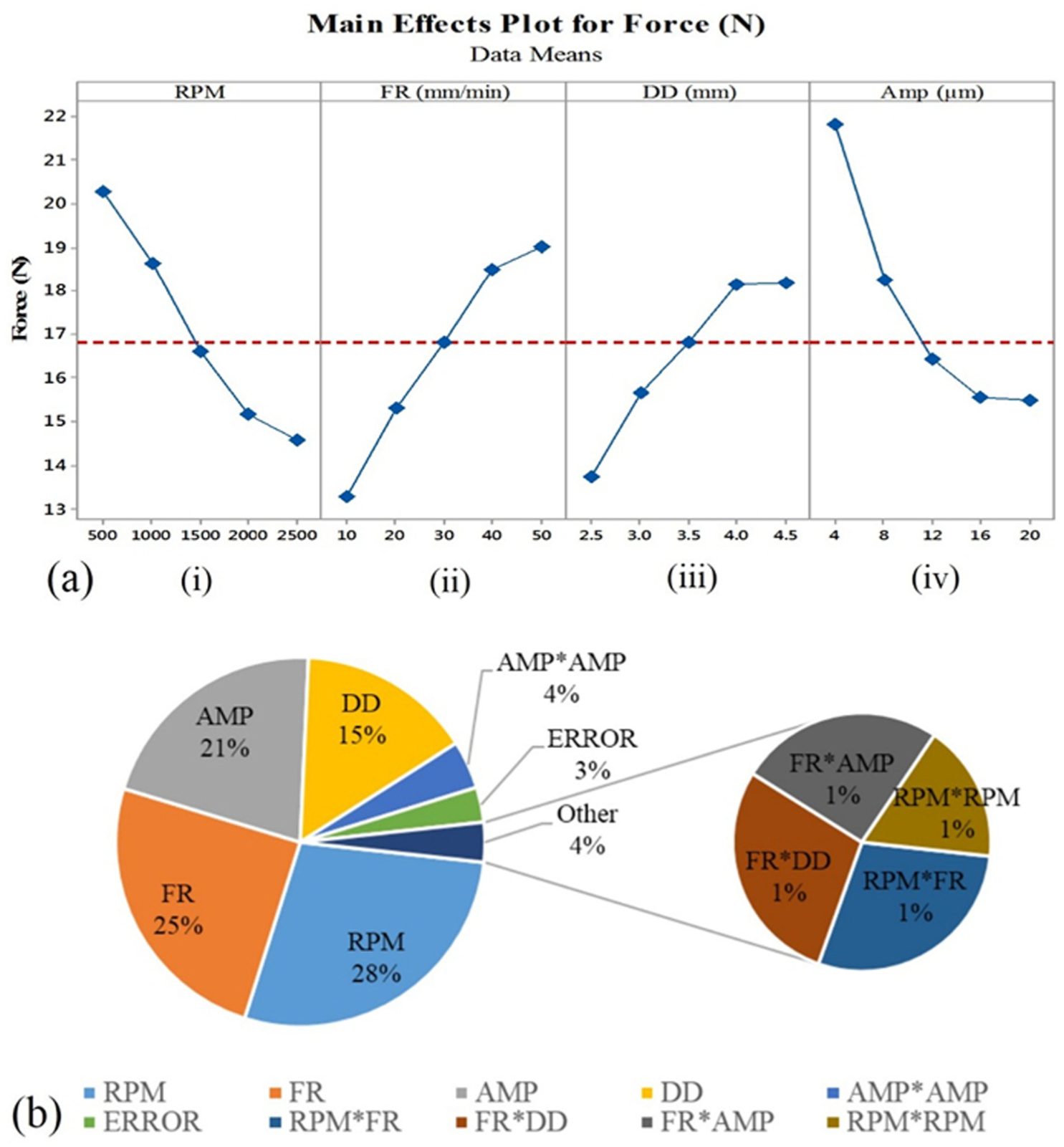
(a) Effect of input process parameters on the force (main effect plot) and (b) percentage contribution of the process parameters for the force.
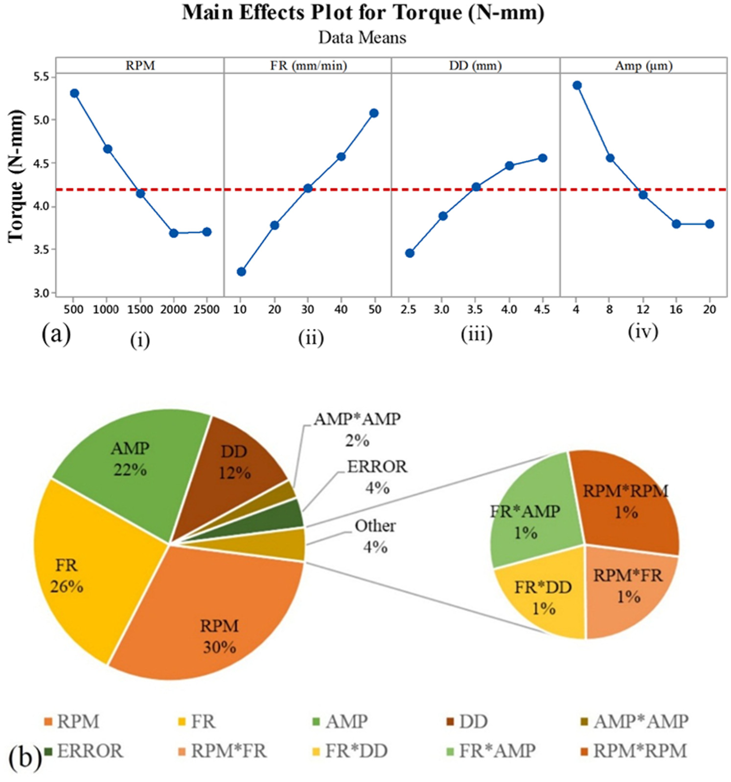
(a) Effect of input process parameters on the torque (main effect plot) and (b) percentage contribution of the process parameters for the torque.
Effect of rotational speed on force and torque
It can be observed from Figure 5(a) (i) that cutting force decreased with increase in the rotational speed. The variations show that the mean thrust force was 20.29 N at 500 r/min and 15.17 N at 2000 r/min, that is, 25.23% reduction in mean force has been observed from 500 to 2500 r/min. Whereas 14.58 N mean force has been observed at 2500 r/min, only 3.88% of force reduction has been observed from 2000 to 2500 r/min. It means that force drastically decreased with increase in the rotational speed from 500 to 2000 r/min and slightly decreased on further increase in the rotational speed. The drop in the thrust force may be due to the different kinds of chips at different speeds, as shown in Figure 7(a)–(c). Chips were obtained at different rotational speeds while keeping other parameters constant. Figure 7(a) also shows that lower rotational speed generated large size chips as compared to the chips formed at higher rotational speed (Figure 7(c)). It may be due to the reason that at lower cutting speed, there is high mean friction coefficient between the tool and workpiece interface;11,17 therefore, cutting forces are higher at lower speed. The obtained result followed the same trend as given by conventional bone drilling, 15 ultrasonic-assisted bone drilling, 17 RUM of CFRP 29 and titanium alloy. 24 Figure 6(a) (i) shows that torque is dropped to 30.552% with increase in the rotational speed from 500 to 2000 r/min. The effect was negligible on the torque after 2000 r/min speed. These results are consistent with the results reported by Wang et al. 15 with conventional bone drilling and Alam et al. 17 with ultrasonic-assisted bone drilling.
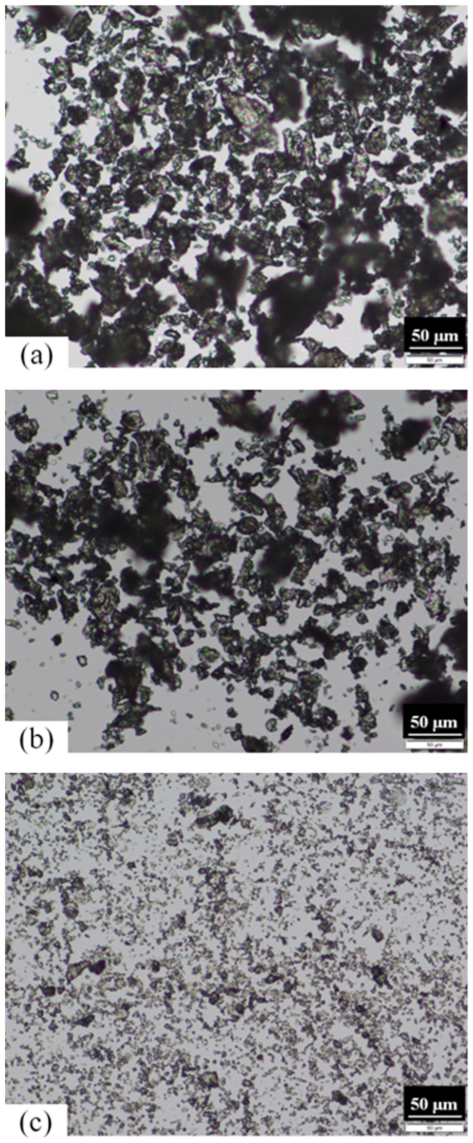
Microscopic images of chips obtained at (a) 500 r/min, (b) 1500 r/min and (c) 2500 r/min (feed rate = 10 mm/min, drill diameter = 4.5 mm, amplitude = 16 µm).
Effect of feed rate on the force and torque
It can be noted from Figures 5(a) (ii) and 6a (ii) that force and torque are also highly influenced by feed rate. Values of force and torque increased continuously with increase in the feed rate. The rise in the force and torque was about 43.22% and 56.54%, respectively, for the feed rate varying from 10 to 50 mm/min. It may be due to the reason that at higher feed rate, more material is removed by the drilling process in a given time, as compared to the lower feed rate. The obtained results follow the same trends as reported by Wang et al. 15 in conventional bone drilling and Cong et al. 29 in RUM.
Effect of drill diameter on the force and torque
Figures 5(a) (iii) and 6a (iii) reveal that force and torque significantly increased with increase in the tool diameter. The increase in the force and torque was observed to be 32.36% and 31.70%, respectively, as drilling diameter varied from 2.5 to 4.5 mm. It is due to increase in the tool diameter, the cross-sectional area and the area to be sheared by the tool increase significantly which results in force and torque.
Effect of vibrational amplitude on the force and torque
Figures 5(a) (iv) and 6a (iv) show that force and torque significantly decreased by 28.60% and 29.64%, respectively, with increase in amplitude from 4 to 16 µm and remain unaffected when amplitude or vibration is further increased. In the ultrasonic machining, the contact time between the workpiece and vibrated tool reduces significantly with high amplitude of the tool. Therefore, the effect of friction between the tool and the workpiece interface during the machining may reduce, leading to a decrease in the force and torque. The obtained results were consistent with the earlier findings of ultrasonic-assisted bone drilling, 17 RUM, 29 UAD on hard and brittle materials. 30
Optimization of the force and torque
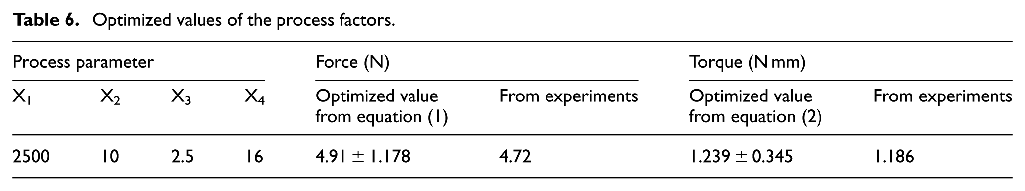
Optimization was carried out for minimizing the value of force and torque for the RUBD process. The parameters were obtained using the objective function given by equations (1) and (2), with the help of the genetic algorithm toolbox which is available with MATLAB software. The values of the process parameters for minimum force and torque during RUBD process are presented in Table 6. For validation, experiment has been done at optimized values of the process parameters.
Optimized values of the process factors.
Mechanism of material removal in RUBD
RUBD is a non-thermal mechanical energy–based material removal process, in which the material is sheared and removed due to interaction of abrasives on the drill tool. The chips produced in the process are tiny as compared to chips produced in CD, and as the amount of material cut is very less as compared to CD or UAD, the deformation energy that gets converted into heat is also very less and causes less temperature rise, that is, of the order of 10 °C. Cylindrical rods are machined out from the bones during drilling in RUBD process, due to the hollow nature of the tools. However, in CD and UAD, such kinds of rods are not produced because chips are completely formed during drilling. Hence, minimum force and torque are generated in RUBD process with respect to the CD. Also in RUBD process, axial ultrasonic vibrations are given to the tool so intermediate contact time between the bone and tool is reduced. Table 7 shows the comparison of the two drilling methods (RUBD and CD) on force and torque, respectively. Scanning electron microscopy (SEM) was also used to observe the microcracks and the surface morphology, as shown in Figure 8. Figure 8(a) shows that no microcracks have been generated on the inner surface of the bone drill with a high speed of 2500 r/min. Few short microcracks have been observed when drilling with a lower speed of 500 r/min, as shown in Figure 8(b).
Comparison of force and torque with RUBD and CD.
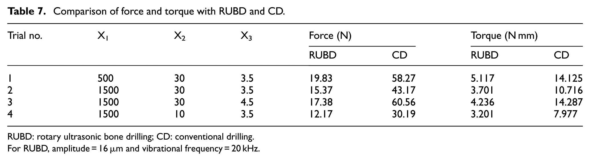
RUBD: rotary ultrasonic bone drilling; CD: conventional drilling.
For RUBD, amplitude = 16 µm and vibrational frequency = 20 kHz.
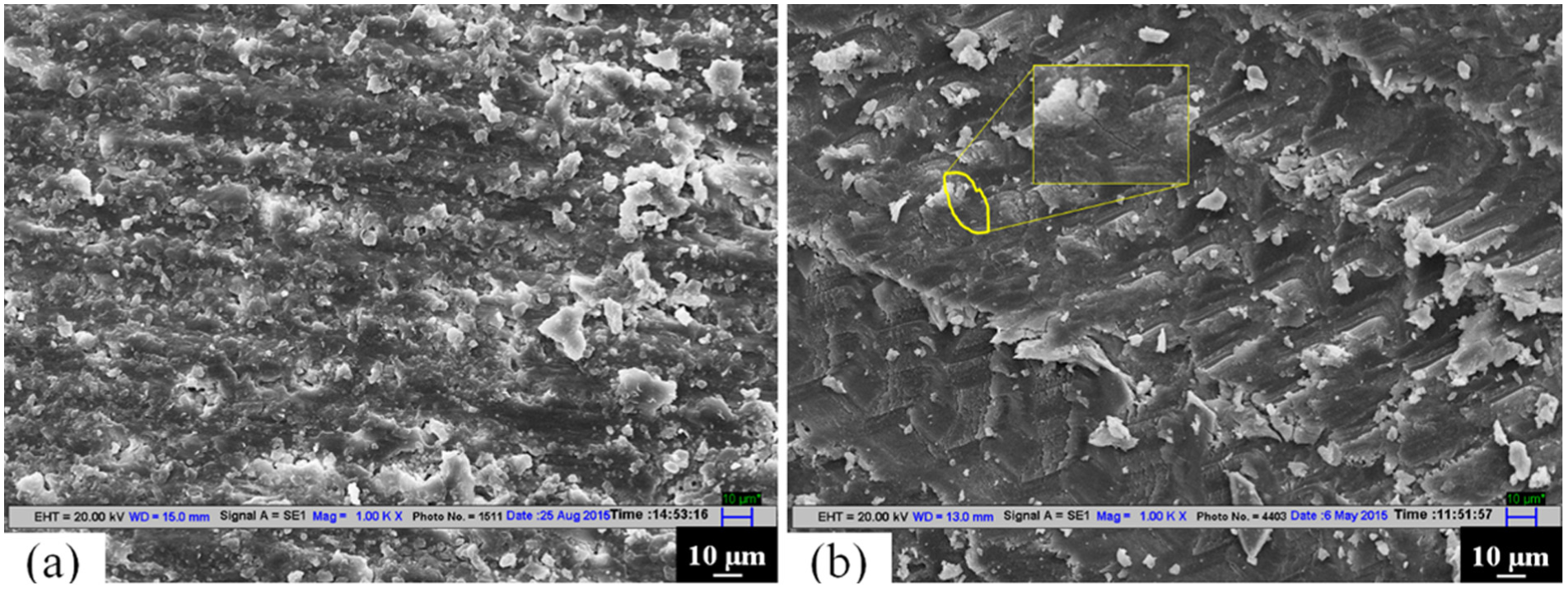
SEM images with 1000× magnification: (a) 2500 r/min and (b) 500 r/min (feed rate = 10 mm/min, tool diameter = 4.5 mm, amplitude = 16 µm).
Conclusion
In this study, the effect of rotational speed, feed rate, drill tool diameter and ultrasonic vibrational amplitude on the force and torque has been studied for the RUBD process, and the following conclusions have been made:
In this work, feasibility of RUBD process has been successfully explored. The RUBD is found to be a potential candidate for orthopedic bone drilling. The force and torque can be minimized with respect to CD and UAD with the proposed process because of the inherent advantages of the process.
Force and torque dropped significantly with increase in the rotational speed and amplitude of the tool, whereas decrease in the feed rate and drill diameter further decreased the force and torque.
The most significant factors that affected the force and torque were rotational speed with percentage contribution of 28% for force and 30% for torque followed by feed rate (25% for force and 26% for torque), vibrational amplitude (21% for force and 22% torque) and drill diameter (15% for force and 12% torque).
Lower rotational speed produced a larger size of chips with respect to chips formed at a higher speed.
The confirmation experiments show that the developed and proposed statistical models lie within the 95% confidential interval.
It is also concluded that no crack has been generated on the inner surface of the bone during using RUBD.
Footnotes
Acknowledgements
The authors are thankful to Dr Ravi Gupta, Professor, Department of Orthopedics, Government Medical College Hospital Chandigarh Sec 32B, India, for his valuable suggestions.
Declaration of conflicting interests
The author(s) declared no potential conflicts of interest with respect to the research, authorship and/or publication of this article.
Funding
The author(s) disclosed receipt of the following financial support for the research, authorship, and/or publication of this article: The authors gratefully acknowledge the financial support provided by EPSRC-DST project titled as MAST to carry out this work.