
Abstract
Drilling is one of the most important machining processes in manufacturing industry. Recently, studies dealing with the problems encountered during drilling and their solutions have been increased. In this study, it is aimed to model and analyze the thrust forces and torques obtained experimentally according to the changes in cutting parameters during drilling processes applied to AISI 316L stainless steel material that has wide usage in industry by using finite element method. For this purpose, a number of drilling experiments were carried out, and the thrust force and torque were investigated experimentally, analyzed, and modeled depending on the cutting parameters (cutting speed and feed rate) and cutting tool types (uncoated and TiN-/TiAlN-/TiCN-coated solid carbide drills). According to the results obtained from experimental studies, thrust force and torque had a tendency to increase subject to increasing feed rates. These parameters had a tendency to decrease in coated tools, while there was no important change in uncoated tools according to increasing cutting speed. According to the results of the analyses, total deformation increased with increasing cutting speed and thrust force for both in coated and uncoated cutting tools. It was seen that developed model can be used successfully in forecasting the results of the analyses.
Introduction
Drilling is one of the most important machining processes and includes approximately 33% of the machining operations. Despite the development of modern machining methods in manufacturing industry, the conventional hole drilling method is still the most widely used machining method due to the economic reasons and the applicability. 1 Because of the lack of knowledge about technological ability in many companies, many problems occur in drilling applications. The varying cutting forces on the cutting tools exposed during drilling operations and chip flow changes can cause the jam of cutting tool in the holes. Chip formation that occurs during drilling process directly affects the cutting forces and temperature and indirectly affects the surface quality and precision of the hole. On the other hand, chip disposability during the drilling processes also directly affects the hole quality and changes according to the cutting parameters (cutting speed, feed rate). These parameters are the most important parameters in drilling and directly affect the temperature occurring during drilling and cutting forces and determine the performance of cutting tool. 2 Drilling holes is one of the most important processes in machining. The important role of drilling holes among other machining operations increases the importance of the steps oriented to solving problems that occur during drilling holes. 3
The literature survey indicated that many researchers have studied the cutting forces generated during drilling processes.4–8 In a previous study, the effect of cutting parameters, which were optimized for glass fiber–reinforced composite material using Taguchi methodology, on cutting force and torque during drilling glass fiber–reinforced composite material was researched. 4 In another study, some drilling experiments on aluminum and brass material containing 7% Si (Cu–Zn38Pb2) using uncoated and diamond-like carbon (DLC)–coated drills were carried out. Cutting forces were measured with Kistler 9271 dynamometer. According to this study, the researcher observed that the average of the thrust force of DLC-coated tool is lower than 2.5 times from uncoated tool. 5 Bagci and Özcelik measured thrust force and cutting temperature occurred during drilling of AISI 1040 versus Al 7075-651 workpiece in vertical machining center. They compared the experimental results with the finite element method (FEM) findings. They showed that the values obtained from FEM analysis are close to the experimental results. 6 Kıvak 7 analyzed the effect of cutting parameters on thrust force, surface roughness, hole quality, and chip formation during drilling super alloy Inconel 718 with coated and uncoated carbide drills in his study. Meral investigated thrust force, surface quality, hole diameter change, and circular and cylindrical deviations in drilling processes experimentally. He used AISI 1050 steel as a reference material whose machinability properties are well known. In this study, 6-, 8-, and 10-mm-diameter uncoated and TiAlN-coated (by physical vapor deposition (PVD) method) high-speed steel (HSS) drills were used. As a result, he determined that coated drills give positive results for all evolution criteria compared to uncoated drills and that the feed rate is a more effective parameter than cutting speed on thrust force. 3 In consequence of literature research, it is seen that researchers are focused on the effect of cutting parameters on cutting forces for varying materials. Additionally, how coating drills affect cutting forces is another important subject that attracts researchers.
In the literature, there are very few studies related to modeling of stresses occurred in cutting tool during the cutting. However, the parameters used to model the stress components require very complex analytical approaches, and the costs of experimental studies are too high. For this purpose, it was aimed to develop highly reliable, economic models easy to apply to real cutting conditions. In mechanics of machining, depending on the combination of the workpiece–cutting tool, cutting parameters, such as cutting speed and feed rate, thrust force, and torque related to these have active role in the chip formation.
In this study, thrust force and torque that occur during drilling AISI 316L austenitic stainless steel material, which has industrially widespread use, have been investigated in computer numerical control (CNC) vertical machining center with TiN-/TiAlN-/TiCN-coated and uncoated solid carbide drills. Austenitic stainless steel materials are one of the most important materials for industrial use nowadays due to their high corrosion resistance and superior mechanical properties. They can be used in both high- and low-temperature industrial applications such as food storage tanks, pressure vessels, and furnace components, and this usage rates are increasing every day.9,10 It is known that there are some problems in machining AISI 316L austenitic stainless steel material. There are lots of studies in literature that evaluate machinability of this material. This study that aims to identify the parameters affecting the drilling of this material was carried out in three stages. The values obtained from experimental studies in the first stage were analyzed by using FEM in the second stage. Finally, in the third stage, a mathematical model was developed for thrust force and torque according to the cutting parameters.
Material and method
In the three-stage study, the first step is “experimental studies.” Various drilling experiments were carried out to determine the effects of cutting forces on thrust force and torque. Data were obtained by measuring the thrust force and torque that occurred during drilling using a dynamometer. In the second stage, an FEM was used in the analysis of mechanical stresses. ANSYS Workbench software package was used for this purpose. In the third stage, a mathematical model was developed depending on the analysis and experimental data.
Experimental studies
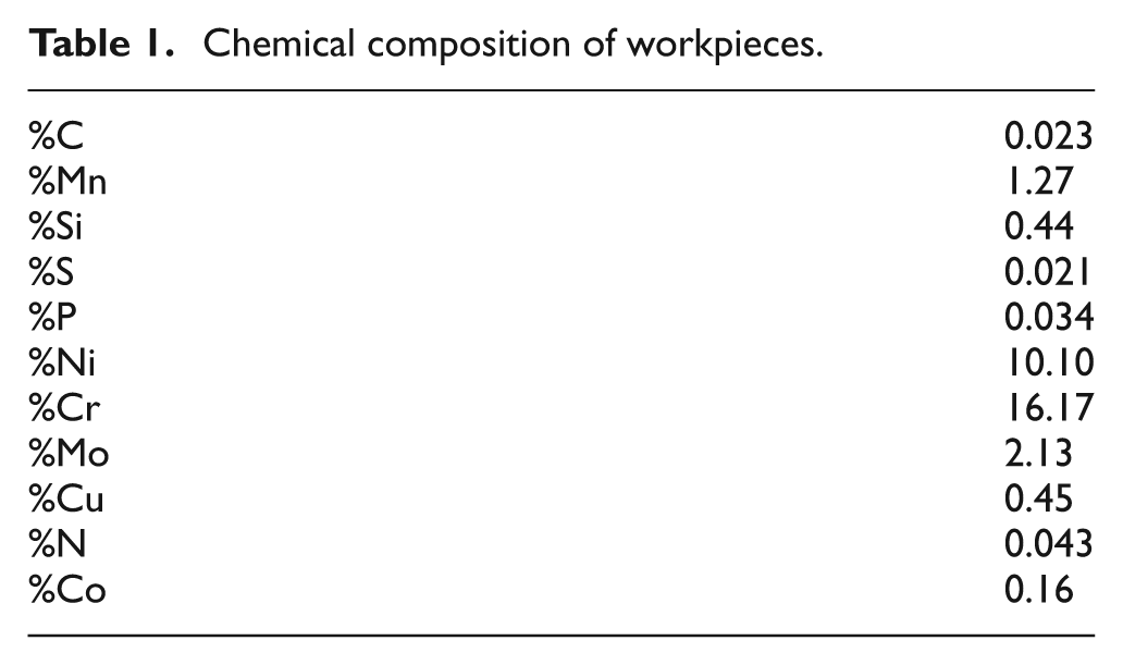
AISI 316L stainless steel was used as a workpiece in the experiments. The chemical composition of the material was identified from its original certificate and is given in Table 1.
Chemical composition of workpieces.
Workpieces were turned to the external diameter of 25 mm. The lengths of workpieces were adjusted to be 35 mm in order to get “L < 3D” condition. For more safe clamping of samples, the part of samples will be fitted to clamping apparatus was turned with shoulder in 20 mm diameter, 10 mm long. The surfaces that will be drilled were ground to prevent the escape of the drill from the center during drilling.
Experiments were carried out by rotary workpiece and stationary tool. In order to hold the drills used in the experiments on the dynamometers safely, rigid and safe clamping apparatus (previously designed and constructed based on clamp mechanism) was used (Figure 1). 8
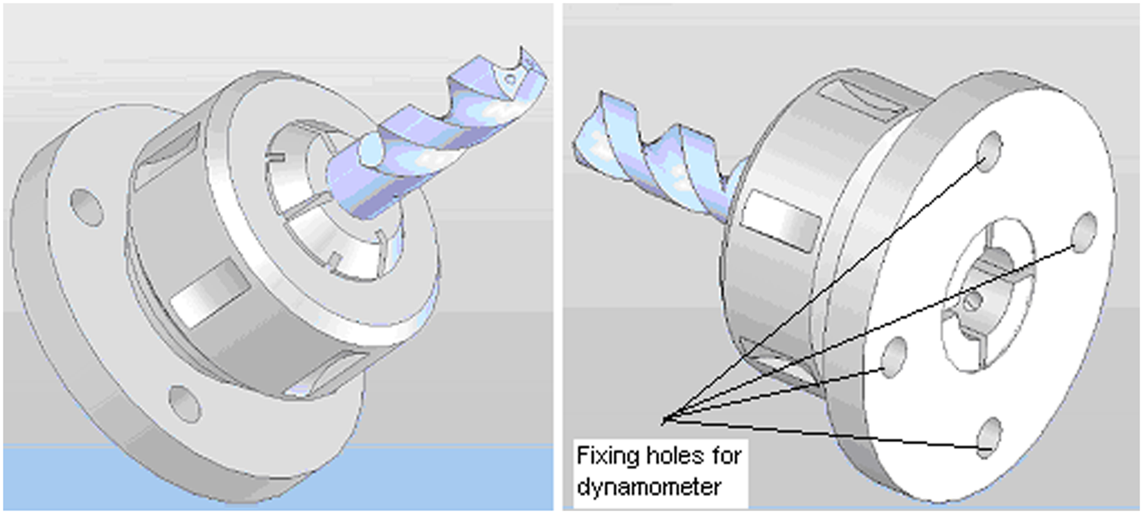
Tool clamping apparatus. 8 .
Drilling experiments were carried out in Johnford VMC-550 CNC vertical machining center. In the experiments, 14-mm-diameter uncoated and coated helical solid carbide drills (5510 series DK460UF; Guhring) were used. It is known that the coatings applied on cutting tools increase the performance of the tool. In order to assess the effect of coating application on drilling operation, uncoated carbide drills and multilayer TiN-/TiAlN-/TiCN-coated carbide tools were used.
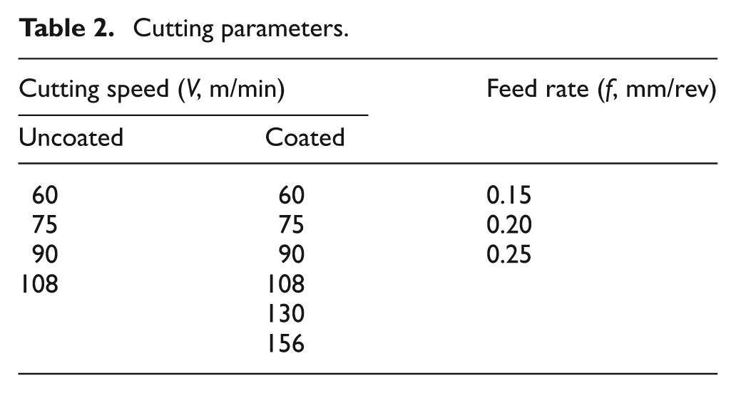
Cutting speed is the basic factor in determining the tool life and affects the power consumption. In addition, it causes mechanical and thermal stresses. The most important factors in determining the cutting parameters are the properties of workpiece and cutting tool material. When determining the cutting parameters, recommended values of material and cutting tool manufacturers were chosen (Table 2). As more high performance was expected from coated tools, two high cutting speeds (130 and 156 m/min) were determined in addition to four different cutting speeds chosen for uncoated tools for comparison. Cutting speed of 156 m/min, which is more than the value recommended by the manufacturer, was chosen for control (or check). The schematic drawing of experimental setup that formed to measure cutting forces and torques that occurred during drilling process is shown in Figure 2. The photographs of uncoated and coated cutting tools used in the experiments are shown in Figure 3.
Cutting parameters.
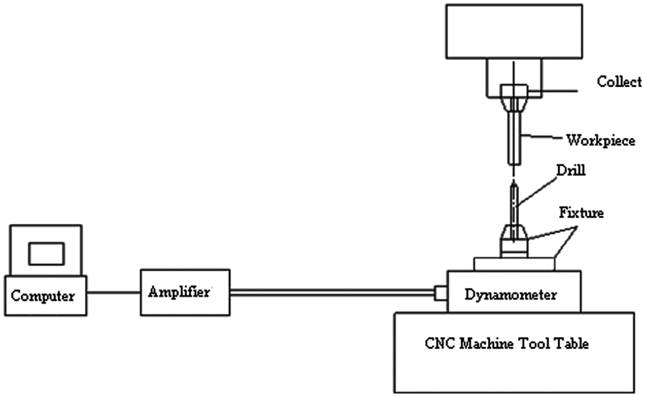
Schematic drawing of experimental setup. 8
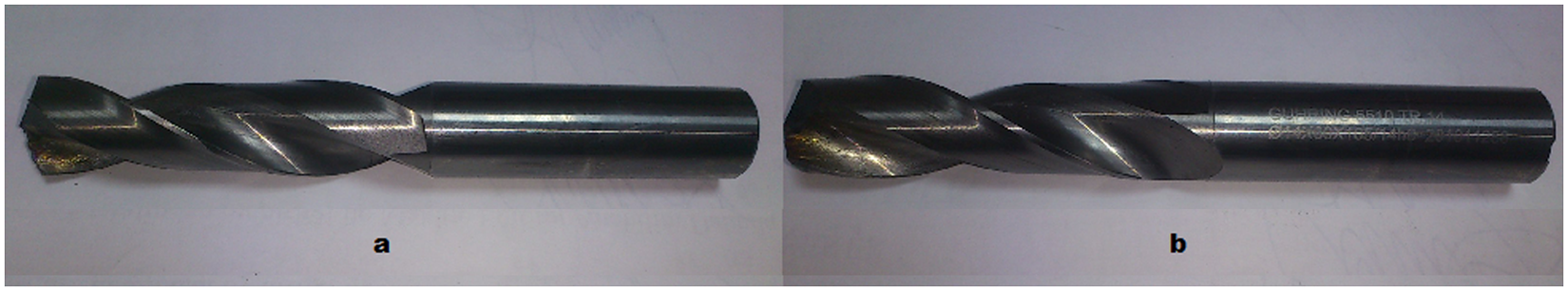
The photographs of cutting tools used in the experiments: (a) uncoated cutting tool and (b) coated cutting tool.
A Kistler 9272–type dynamometer works based on quartz crystal principle that can measure three cutting speed components (FX, FY, FZ) and torque (MZ) at the same time, and a Kistler Type 5070 Amplifier and DynoWare program were used to determine cutting forces and torque experimentally. The graph showing cutting forces and torque that obtained by DynoWare program is shown in Figure 4. The averages obtained from the regular tendency region of graphs were transferred to tables and figures that are composed to evaluate the results of the experiments.
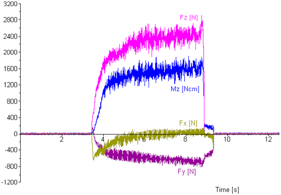
An example of DynoWare Graphs of the forces and torque determined by Kistler 9272–type dynamometer. 8 .
Studies of analysis
Some preparations were made before the analysis of the stresses occurred on drill. The preparations can be summarized as follows:
The design of solid models of the cutting tools;
The modeling of materials necessary for cutting tools;
The determination of type and size of the element to be used;
The separation of the solid models to elements (meshing);
The determination of boundary conditions;
The determination of loading status;
The choice of the method of solution that will be used.
Thrust force (FZ) and torque (MZ) were separately measured according to the change in the cutting parameters simultaneously. The cutting tool (drill) was dimensioned using the information received from the catalog of Guhring cutting tool and measurements obtained directly from used cutting tool.
Design process of the solid model for uncoated and coated drills consists of two phases. Solid models were generated using Solid Works 2010 program and then imported by the help of parasolid extension “.x_t” in ANSYS Workbench. During the process of solid modeling, while taking account of all the geometric parameters (clearance angles, etc.) of the drill in order to shorten the solid modeling and analysis time, instead of the full length of drill, extension length from the tool holder was used. In addition, the tool–chip contact area (on the drill tip) where thrust force and torque were applied depending on the feed rate value was determined.
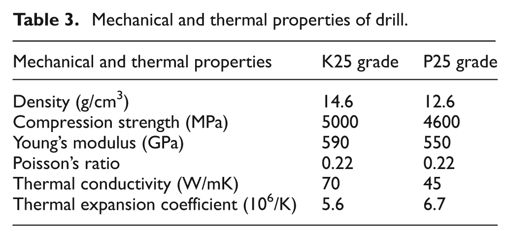
In the second phase of the preparations, the necessary material models were generated for uncoated and coated drills. Linear elastic material model was used in the analysis, and for these models, various studies in the literature have been investigated to obtain necessary information. The mechanical and thermal properties of uncoated (K25 grade) and coated (P25 grade) drills used in the experiments for the stresses analyses are given in Table 3. 11
Mechanical and thermal properties of drill.
In the next stage, for drills whose material models were defined, element types were determined and element separation process (meshing) was conducted in solid models. For uncoated and coated drills used in the experiments, three-dimensional, 10-node quadratic tetrahedron element SOLID187 was used. SOLID187 has a quadratic displacement behavior and is well suited to modeling irregular meshes (such as those produced from various computer-aided design (CAD)/computer-aided manufacturing (CAM) systems). The element is defined by 10 nodes having three degrees of freedom at each node: translations in the nodal x, y, and z directions. The element has plasticity, hyperelasticity, creep, stress stiffening, large deflection, and large strain capabilities. It also has mixed formulation capability for simulating deformations of nearly incompressible elastoplastic materials and fully incompressible hyperelastic materials. Therefore, SOLID187 element was chosen for a fine modeling of the drill including curvilinear surfaces. In the element separation process, the element sizes were applied less frequently (element size = 2 mm) for all the drill geometries, and they were more intense (the element size = 0.05 mm) on the surface of the tool–chip contact area where thrust force and torque will be applied. For all the uncoated and coated drill geometries, 54,811 elements and 87,475 nodes were used.
After generation of solid model geometry and material models, choosing of element type and dimension of elements will be applied; one of the procedures that must be done before the stress analysis is the determination of the loading status and the initial and boundary conditions. Various approaches were followed in the literature on how to apply cutting forces in the element structure generated for the analysis.12–14 Parallel to the literature, thrust force and torque were applied to the tool–chip contact area. In order to simplify the FEM with the aim of reducing the solution period, some assumptions listed below were made according to the literature:
Drills were new.
It was assumed that displacements, proportional to applied loads and according to solid model geometry, are very small in size, and when applied load was removed, drills returned to their original state.
Analysis for static condition was carried out, and it was assumed that there is no vibration.
As a boundary condition, on the surface corresponding to the length of the connection of drill machine, the displacement in all directions was selected as 0.
Following the analysis procedure described above, for uncoated and coated drills, a total of 30 analyses (12 and 18 analyses, respectively) were conducted. In the analysis, the results of total deformation (Δ), equivalent stress (von Mises stress, SEQV), and maximum and minimum principal stresses (S1 and S3, respectively) that occurred in the drill and that have effects especially on chip surface, primary cutting edge, auxiliary cutting edge, and wear in cutting tools were used.
Modeling of stress components
In this study, in modeling of total deformation and stress components occurred in drill, it is assumed that stress and deformation varied according to the thrust force affecting drill, torque, and feed rate. According to this assumption, a model was developed for total deformation (Δ), equivalent stress (von Mises stress, SEQV), and maximum and minimum principal stresses (S1 and S3, respectively) that are given in equation (1)

where Ri is the calculated total deformation (mm) and stress results (MPa); c is a constant for uncoated and coated drills; FZ and MZ are the thrust force (N) and torque (N mm), respectively; ƒ is the feed rate value (mm/rev); m, n, and p are the exponents for thrust force, torque, and feed rate, respectively, for the uncoated and coated drills.
As the calculated total deformation and stress results (Ri) were determined with the help of ANSYS Workbench stress analysis, in order to solve equation (1), constant c, depending on the type of drill (uncoated and coated), and m, n, and p exponents needed to be calculated. For this purpose, equation (1) was converted to a logarithmic form, as shown in equation (2)

and then converted to a linear form using equation (3)

where Y is the logarithmic value of estimated total deformation and stress components (e.g. log S1); β1, β2, and β3 are the equation coefficients (m, n, and p exponents, respectively); X1, X2, and X3 are log FZ, log MZ, and log f values, respectively; and ε is the error term. In equation (3), β0 and X0 will be used to determine the constant c according to the drill type (uncoated and coated); also, X0 was discussed as an imaginary variable and assumed to be 1.
Equation (3) contains one dependent variable (Y) and three independent variables (X1, X2, and X3). So equation (3) and accordingly equation (1) were solved by using regression analysis, which is a statistical analysis technique that characterizes the relationship between two or more variables that have cause–effect relationship, with a mathematical model called regression model in order to make estimations and predictions about that subject. Equation (3) takes place in the scope of “multiple linear regression analysis” among the regression analysis types. Therefore, equation (3) (the estimation of coefficients β0, β1, β2, and β3) was solved using the least squares method. Accordingly, indication of equation (3) in matrix form for each of the drill types is given as follows
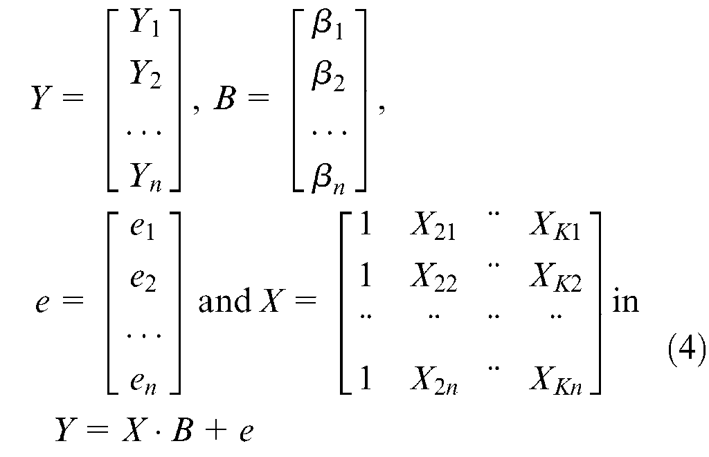
where n and K are the numbers of experiments and analyses, respectively; Y is the n × 1 size of vector of dependent variables; X is the n × K size of the matrix of independent variables; B is the K × 1 size of vector of the model constants; and e is the n × 1 size of vector of error terms.
In multiple linear regression analysis, estimation of parameters (model constants vector) is made using the least squares method, minimizing sum of the squares of differences between the actual (determined with the help of ANSYS Workbench) and theoretical (calculated) values. Accordingly, the necessary arrangements are made, the model vector of constants and therefore equation (1) for uncoated and coated drills, the solution for calculating the exponents of thrust force (m, n, and p), torque, and feed rate value takes the form of15–19

where X′ represents the transpose of independent variables matrix,
As mathematical modeling processes were made with a specific error (the difference in the value of analysis result with the value calculated by modeling) value, the average of the sum of these errors should be minimized. This value is desired to be minimized (mean squared error (MSE)) and at the same time is a criterion that determines the performance of the model. Root mean square (RMS), coefficient of determination (R 2 ), and mean absolute percentage error (MAPE) were taken as criteria for suitability of the results that are calculated at the end of the modeling and the results of the real analysis. In addition, the percentage error values of all the total deformations and stress values that were found as a result of modeling were determined.
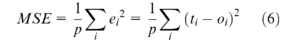
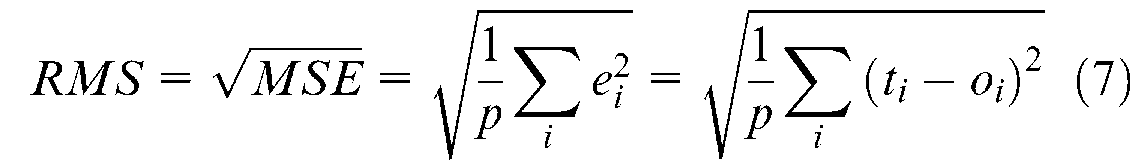
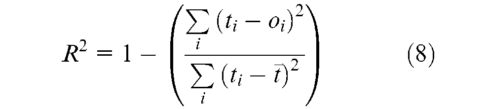

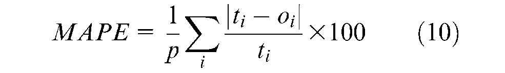
In equations (6) to (10), ei, ti, oi, p, and
Results and discussion
Experimental results
Measurement results of thrust force (FZ) and torque (MZ) achieved from experiments for uncoated and coated drills are shown in Figures 5 and 6, respectively.
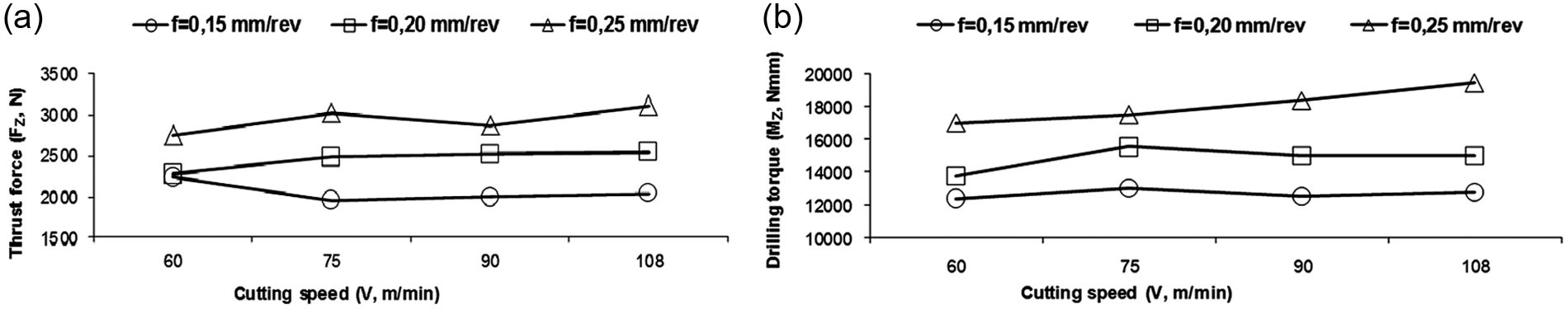
Experimental results for uncoated drills: (a) thrust force and (b) torque.
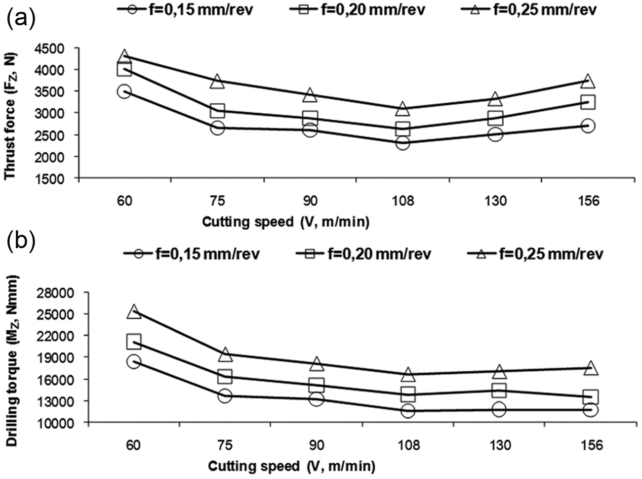
Experimental results for coated drills: (a) thrust force and (b) torque.
For both uncoated and coated drills (Figures 5 and 6), change in torque had similar tendency as the change in thrust force. This was realized as expected. When the experimental results for thrust force shown in Figures 5(a) and 6(a) are evaluated, generally it is seen that thrust forces increase with the increase in feed rates. This can be referred to increased chip section according to the increase in feed rates. The increase in necessary power for material removal resulted in increase in the chip section causing increase in thrust forces as well. 20
When the changes in force and torque according to the cutting speed are evaluated, tendency to decrement was observed in thrust forces and torque according to the increasing cutting speed for coated drills (Figure 6), while no important change was observed for uncoated drills (Figure 5). This tendency to decrement was clearer especially passing from 60 to 75 m/min. This was an indicator that the cutting speed of 60 m/min is low and not suitable for coated drills. On the other hand, when the cutting speed was increased from 130 to 156 m/min, a tendency to increment started again especially in thrust force. The cutting speed of 156 m/min is more than the recommended value by the manufacturer for drills; consequently, tool starts wearing after reaching this cutting speed. Continuing material removal with wearied tools will cause increment in cutting forces. 7 The highest values of thrust force and torque were obtained in the feed rate. The highest values in terms of cutting speed were obtained at the lowest speed (60 m/min) for coated drill and at the highest speed (108 m/min) for uncoated drill. Obtaining the highest values of thrust force and torque in 60 m/min was referred to the thrust force below the recommended range for coated tools and to the tightening of the deformation occurred during chip removal. The reason to use the cutting speed of 60 m/min for coated tools was to use the same parameters for both the cutting tool types and to show that the cutting speed is not suitable for coated tools. In uncoated tools, large changes depending on the cutting speed in terms of thrust force and torque were not observed. There is a slight increase only in the cutting speed of 108 m/min. This can be referred to acceleration of tool wear process due to excess of the recommended cutting speed range for cutting tool. These aspects have been added in this article.
Results of analysis
The vectorial sum of the deformations in x, y, and z directions gives the total deformation. The material and wear behavior of the cutting tool are important points affecting the performance. Effective stresses during chip removal and deformation and the regions where these factors affect determine wear behavior and tool life of the cutting tool. Consequently, total deformation, equivalent stress (von Mises stress), maximum principal stress, and minimum principal stress are calculated based on experimentally measured data (torque and thrust force). According to the changes in cutting parameters, an investigation on total deformation, equivalent stress (von Mises stress), maximum principal stress, and minimum principal stress that occurred in uncoated and coated drills was carried out. The results of this investigation are shown in Figure 7. The results of coated drill are indicated with notation “C.”

Parameters according to tool type: (a) total deformation, (b) equivalent stress (von Mises stress), (c) maximum principal stress, and (d) minimum principal stress.
Total deformation (Figure 7(a)) increased with increasing cutting speed and thrust force for both coated and uncoated drills. When equivalent stress is evaluated, it was seen that the highest stress value was observed at 60 m/min and 0.15 mm/rev cutting conditions (Figure 7(b)). This is referred to chip–tool contact area that became small when the feed rate was 0.15 mm/rev. Equivalent stresses occurred similar to the changes of thrust force that experimentally obtained. Equivalent stress had the tendency to decrement with increasing cutting speed for coated drills while there was no important change for uncoated drills. Only in the cutting speed of 156 m/min, there was a tendency to increment same as experimental thrust forces. This situation is referred to the fact that cutting speed was more than the recommended values, and tool has exposed to a faster wear process, as determined in the interpretation of the experimental results. When maximum and minimum principal stresses were evaluated, it is seen that the compressive stresses were more effective than tensile stresses for both types of drills for all cutting conditions (Figure 7(c) and (d)). This situation developed depending on the vectorial direction of active forces.
Variations of total deformation, equivalent stress (von Mises stress), maximum principal stress and minimum principal stress that occurred in uncoated and coated drills are shown in Figures 8 and 9, respectively. While maximum total deformation occurred at the cutting speed of 108 m/min and the feed rate condition of 0.25 mm/rev, in the analysis performed with uncoated drills, equivalent stress (von Mises stress), maximum principal stress, and minimum principal stress values were obtained at the cutting speed of 60 m/min and the feed rate cutting condition of 0.15 mm/rev. While maximum total deformation occurred at the cutting speed of 60 m/min and the feed rate of 0.25 mm/rev, in the analysis performed with coated drills, equivalent stress (von Mises stress), maximum principal stress, and minimum principal stress values were obtained at the cutting speed of 60 m/min and the feed rate condition of 0.15 mm/rev.
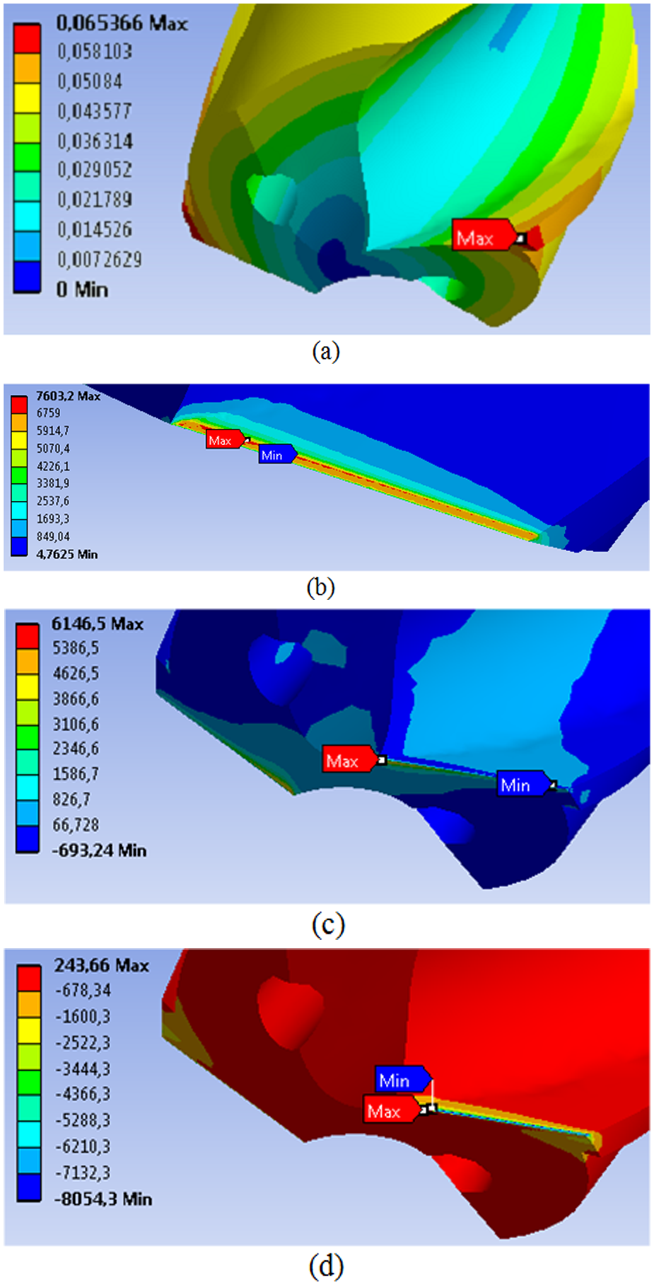
For uncoated drill, variations of (a) total deformation, (b) equivalent stress (von Mises stress), (c) maximum principal stress, and (d) minimum principal stress.
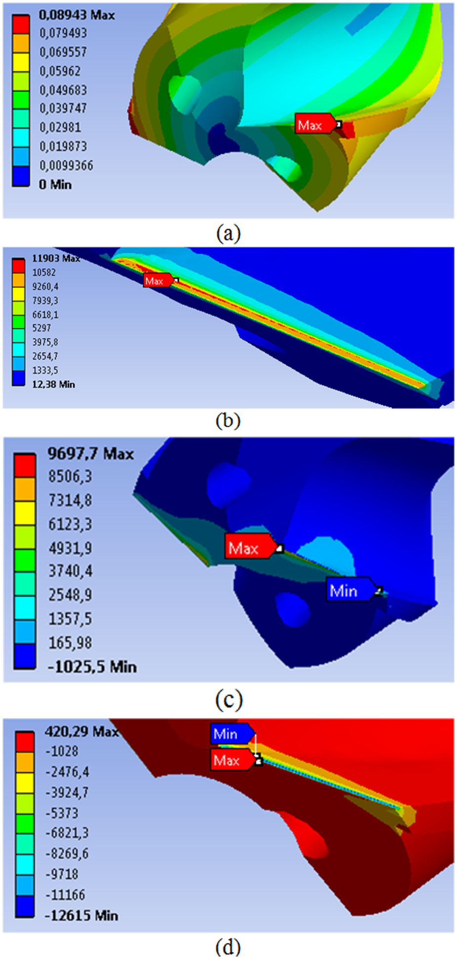
For coated drill, variations of (a) total deformation, (b) equivalent stress (von Mises stress), (c) maximum principal stress, and (d) minimum principal stress.
Model results
Exponent values m, n, and p and constant c defined in equation (1) were determined by solving equation (5) for each drill type. The findings about calculated model constants and other statistical evaluation results (MSE, RMS, R 2 , emax%, MAPE) are given in Tables 4 and 5.
Calculated model constants and other statistical evaluation for uncoated drills.
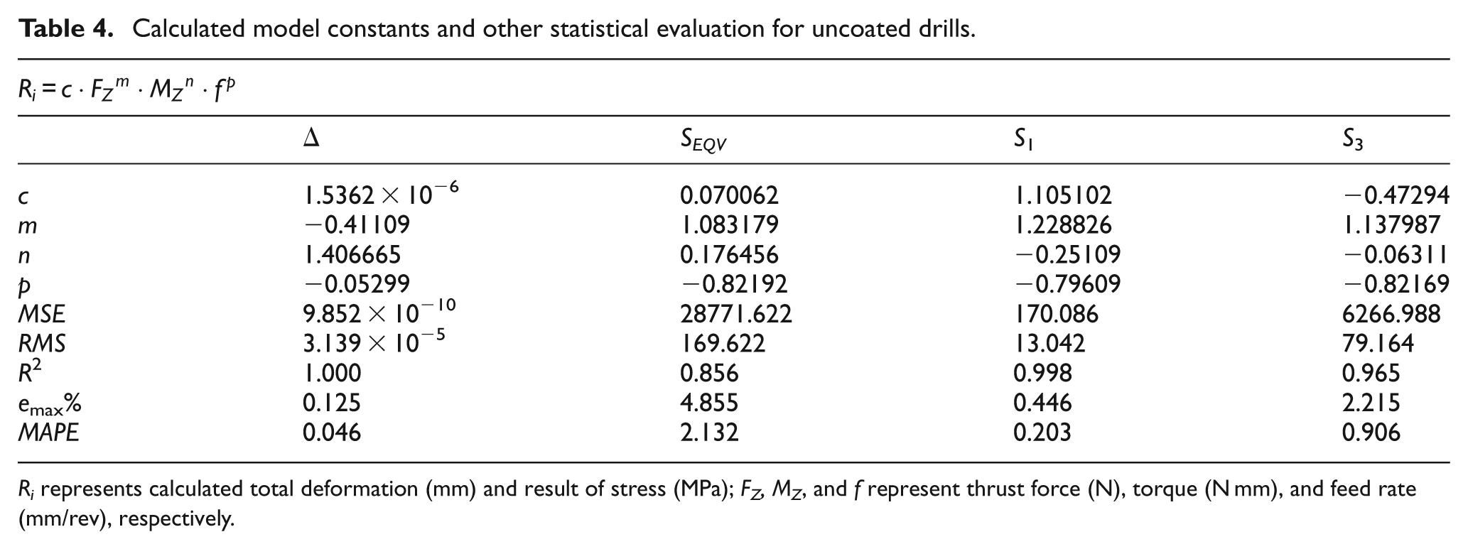
Ri represents calculated total deformation (mm) and result of stress (MPa); FZ, MZ, and f represent thrust force (N), torque (N mm), and feed rate (mm/rev), respectively.
Calculated model constants and other statistical evaluation results for coated drills.
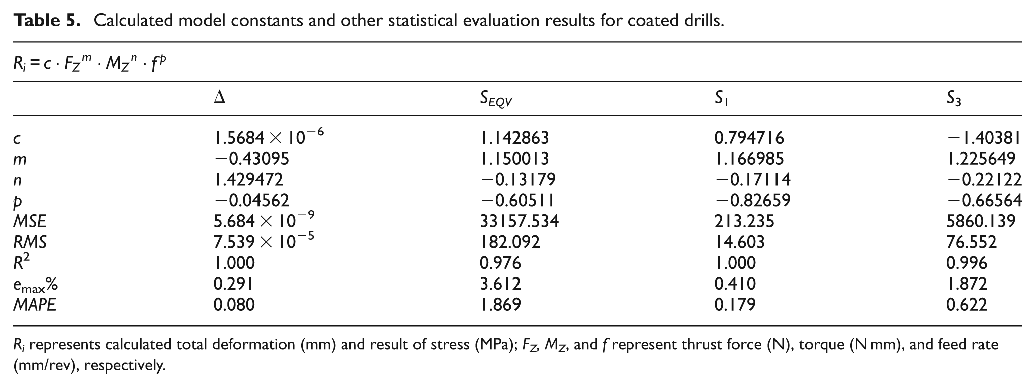
Ri represents calculated total deformation (mm) and result of stress (MPa); FZ, MZ, and f represent thrust force (N), torque (N mm), and feed rate (mm/rev), respectively.
The results of total deformation determined by ANSYS Workbench, equivalent stress (von Mises stress), maximum principal stress and minimum principal stress, and the results of model according to the tool type (uncoated and coated) are shown in Figures 10 and 11, respectively. Model results are indicated with notation “M.”

The results of analyses and model for uncoated drill: (a) total deformation, (b) equivalent stress (von Mises stress), (c) maximum principal stress, and (d) minimum principal stress.

The results of analyses and model for coated drill: (a) total deformation, (b) equivalent stress (von Mises stress), (c) maximum principal stress, and (d) minimum principal stress.
It is seen that the results of analysis and that of the developed model were in compliance with each other (Tables 4 and 5 and Figures 10 and 11). Specificity coefficient was between 0.96 and 1.00 for all stress results and total deformation for all cutting tool types except the results of equivalent stresses of uncoated drills (0.856). This condition in the specificity coefficient for both coated and uncoated drills reflected to MAPE values with about 2% deviation. In general, it can be concluded that model results can be used safely in predicting the results of analyses.
Conclusion
The results of this study that aimed at modeling and analyzing experimentally obtained thrust force and torques depending on the changes in cutting parameters by FEM in drilling process applied to AISI 316L stainless steel materials are summarized as follows:
The data obtained from the experimental studies showed that the changes of thrust force and torque had similar tendencies according to the cutting parameters.
Thrust force and torque had tendency to increment with increasing feed rates and had tendency to decrement in coated drills, while no important change was observed in uncoated drills with increasing cutting speed.
The highest values of thrust force and torque with the highest feed rate (0.25 mm/rev) were observed in the highest cutting speed (108 m/min) for uncoated drills and in the lowest cutting speed (60 m/min) for coated drills.
According to the results of the analyses, total deformation increased with increasing cutting speed and feed rate for both coated and uncoated drills.
Maximum equivalent stresses occurred in the lowest cutting conditions parallel to the chip–tool contact area that becomes smaller.
For both drills and for all cutting conditions, compressive stresses were more effective than tensile stresses.
It can be said that the results of analyses and the results of developed model are in compliance with each other, and in general, developed model can be used successfully in forecasting the results of analyses.
As the tool wear was not evaluated in this study, the researches regarding the relations between wear tendencies and regions that the highest equivalent stresses occurred densely and the regions of probable tool wear occurred are ongoing.
Footnotes
Funding
This research received no specific grant from any funding agency in the public, commercial, or not-for-profit sectors.