
Abstract
The roll-to-roll imprinting technology is considered as the most promising process for manufacturing large-area microstructured surface in a high-precision, high-efficiency and low-cost way. However, the existence of cutting burr of microstructures on roll die will deteriorate the quality of microstructures on target surface in roll-to-roll imprinting processing. For electroplated copper material, this article presents the influence of chip interference on burr in cutting process. The parameter that illustrates the level of chip interference is deduced. The influences of cutting depth and included angle of V-shaped diamond tool on burr height of V-grooves are revealed by analyzing the chip interference. A series of experiments are carried out to verify the theoretical study. The results show good agreement between theoretical derivation and experimental analysis. The reason for chip interference of cutting process is made clear. Then, the optimal process of multi-step cutting process was given as the guidance to enhance the surface quality of micro V-grooves on electroplated copper roll die. With the optimal cutting parameters, the high-quality surface of micro-prism array is achieved.
Introduction
Sorts of microstructured surfaces are highly required in the fields of concentrated photovoltaic systems, display devices, drag reduction films and traffic signs and so on. Currently, the roll-to-roll (RTR) imprinting technology is one of the most mainstream technologies which can manufacture the large-area microstructured surfaces in a high-precision, high-efficiency and low-cost way.1 -4 The roll die with microstructured surface is used to imprint the target surface and then the high-precision microstructures on target surface can be obtained with subsequent processes. Thereinto, the electroplated copper roller with microstructured surface is employed as the frequently used roll die. The ultra-precision manufacture of electroplated copper roll die with microstructured surface is one of the most important processes in RTR imprinting technology. Due to the advantage of deterministic nano-scale machining using single-crystal diamond tools, the ultra-precision diamond turning has been considered as the best process for the ultra-precision manufacture of roll die with microstructured surface. 5 Although the high-quality optical surface and sub-micron form accuracy can be achieved with the single-crystal diamond tool which possesses good sharpness and high resistance to wear,6,7 the ultra-precision machining quality of different microstructured surface still depends on those respective optimal processing parameters. Hence, the high-precision manufacturing of roll die with microstructured surface attracts researchers’ concerns.
Tae-Jin et al.8,9 have finished the fabrication of complex micro-prism patterns on electroplated copper roll die surface using the ultra-precision lathe, which adopted the multiple threads cutting method. In addition, the pitch error of micro-prism patterns on large roll die surface can be well avoided with the employment of precise temperature control. Le et al. 10 proposed a theoretical model of predicting the micro burr size in grooving prism and pyramid patterns, but the side burr height of prism pattern predicted by this model is inaccurate when the angle of prism pattern exceeds 90°. Min et al. 11 presented the experimental investigation about the chip formation process and the burr topography variation between single-crystal copper and polycrystalline copper in micromachining. Li et al. 12 have carried out the micro V-shaped grating cutting experiment, in which the cutting burr of micro V-shaped grating was markedly reduced by modifying the cutting tool’s shape and improving the cutting process and the influences of material metallographic homogeneity on the cutting burr were also analyzed. However, the material (H62 Copper) adopted in micro V-shaped grating cutting experiment exists with uneven metallography and lower hardness, which differs from the electroplated copper. Chao et al. 13 put their efforts on the influence of the plunge-cut and spiral-cut method on the surface quality and burr formation of micro pyramid patterns, but some experiments and simulation results contradict with the previous experimental and theoretical results. Zhang and colleagues14,15 have finished the high-precision linear Fresnel lens and radial Fresnel lens on roll dies by introducing a five-axis ultra-precision machine tool.
Although many researchers have made great efforts on the studies about the machining of microstructures, the influence of chip interference on burr height in cutting process is still seldom studied especially for the electroplated copper roll die. This article introduces several important impact factors on burr formation. Shape ratio of chip is deduced as presenting the level of chip interference which obviously influence burr height. Included angle of V-shaped diamond tool and cutting depth were also analyzed to reveal their influences on burr height by cutting experiments. Furthermore, optimized cutting parameters were achieved according to above theoretical analysis and experimental verification.
Processing method and material shape ratio
This part introduces the chip interference phenomenon which is an important impact factor of burr height. The relevant theory is illustrated in experimental results. Then, the process method of micro V-grooves is presented. Based on this process method, the shape ratio that presents the level of chip interference is deduced.
The chip interference
During the cutting process, a transition process happens to the chip formation changing from non-free type to free type. Figure 1(a) and (b) shows the chip deformation comparison between the first and second step cutting in two-step cutting method, respectively. Contrasting with single-step cutting method, the chip type after the first step cutting should be closer to free morphology in multi-step cutting method. Preliminary analysis suggests that the middle part of the undeformed chip in multi-step cutting method, which is thinner than that in single-step cutting method, can improve the chip flow ability and weaken the chip interference effect. In other words, both sides of the chip after the first step cutting, which are cut synchronously by two cutting edges of the V-shaped diamond tool, would not extrude each other due to the morphology of V-shaped undeformed chip.
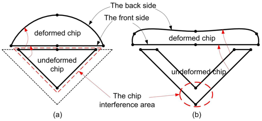
The chip deformation comparison in two-step cutting method: (a) chip deformation in the first cutting and (b) chip deformation in the second cutting.
Multi-step cutting method
In the machining of micro V-grooves, multi-step cutting method is recommended. Figure 2 shows the multi-step cutting method with spiral-cut path. For this cutting method, the cutting depth and feed rate depend on the designed pitch of micro-prism patterns. The black area in Figure 2 is the undeformed chip area of each cutting step in multi-step cutting method.
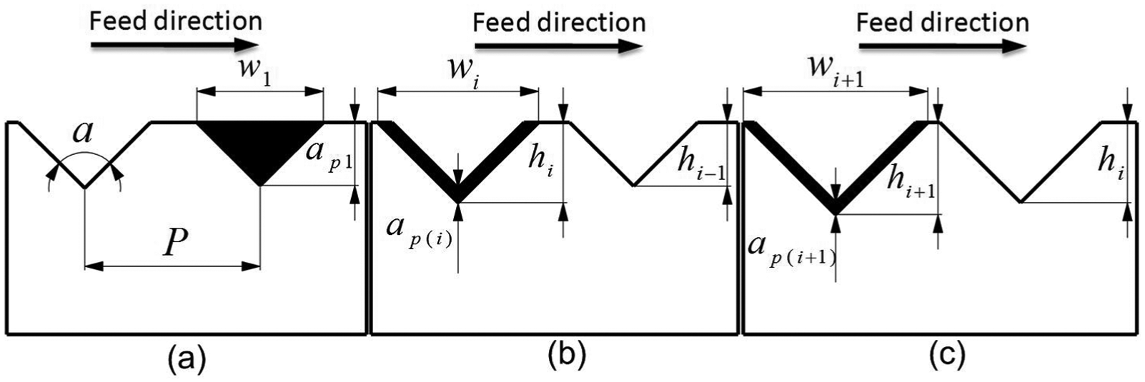
Multi-step cutting method of micro-prism array: (a) the first step cutting, (b) the ith step cutting and (c) the final step cutting (where P is the pitch of micro-prism array; α is the tool included angle;
The calculation of material shape ratio
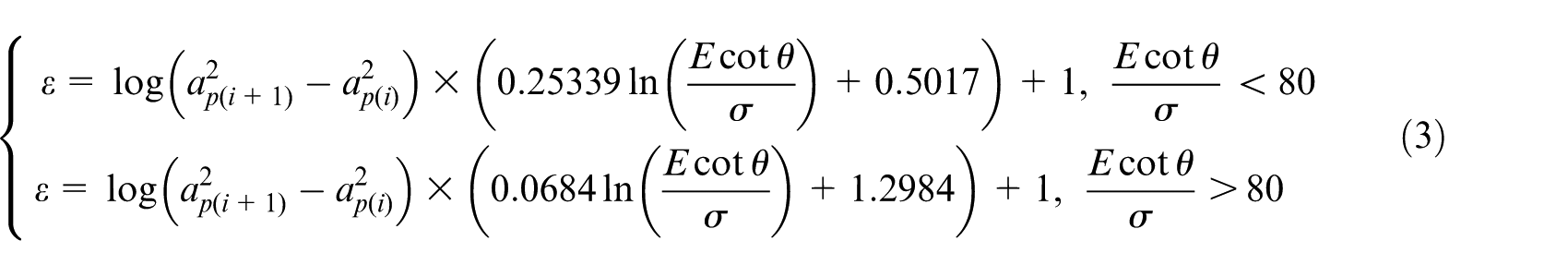
Based on the multi-step cutting method, a token parameter is deduced to present the level of chip interference. Rheological factor 16 X is first given in study of scratch test on material flow and is presented as
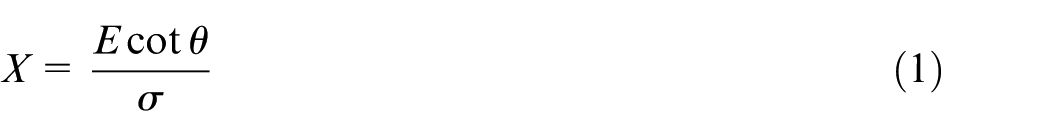
where E is the elastic modulus of material,
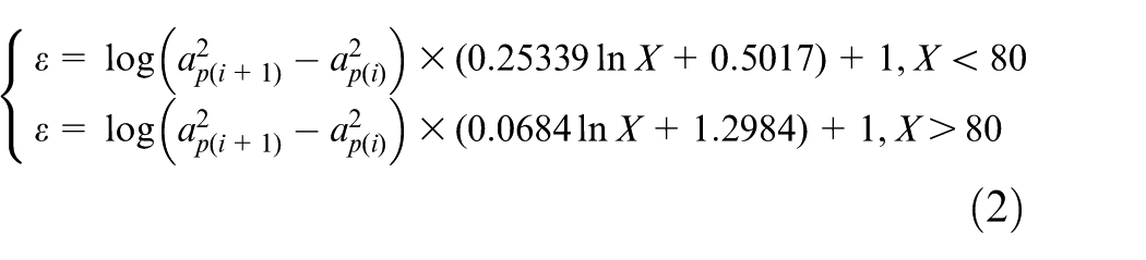
where
Experimental results and analysis
The burr formation is inevitable during the cutting of electroplated copper roll die because the burr cannot be eliminated completely in the metal micro cutting. 18 Microstructure defects on the roll die surface can directly affect the surface quality of imprinted microstructures. In this study, the relationships between burr height and process parameters, such as the included angle, cutting depth and multi-step cutting depth, are investigated by a series of cutting experiments.
Experimental system
Experimental setup for machining micro V-grooves is shown in Figure 3. The specifications of the cutting system are listed in Table 1. This system is based on the home-made drum roll lathe which possesses the ability of X-Z-B-C four-axis motions. Due to the large dimension of workpiece, it is difficult to directly acquire the features of micro V-grooves by current measuring instruments. The compact flat workpiece with electroplated copper is applied in the cutting experiments, instead of roller workpiece. The CCD camera is employed to assist tool setting, which can bring the tool setting error down to 0.2 µm. The stylus profiler (Form Talysurf, Taylor Hobson) is used to measure micro V-grooves on the flat workpiece and then the burr height of micro V-grooves can be obtained, as shown in Figure 4.
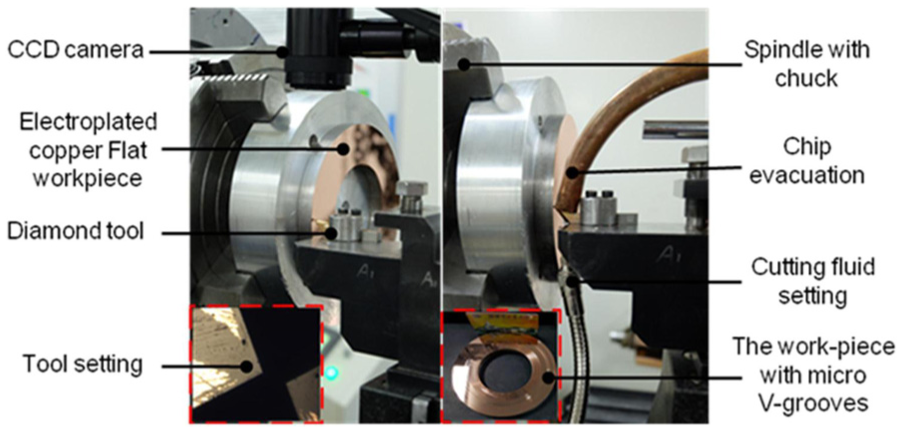
Experimental setup.
Specifications of the cutting system.
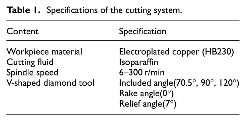
The measurement of burr height.
Effect of cutting depth
This experiment is carried out for discovering the influence of cutting depth on the burr height. Sorts of cutting depth are set as 1, 2, 4, 9 and 19 µm with single-step cutting process, the spindle speed is 300 r/min and the included angle of V-shaped diamond tool is 90°. As shown in Figure 5, the burr height increases with the rise of shape ratio which presents the level of chip interference at different cutting depths. It means that large cutting depth intensifies the chip interference. Meanwhile, the burr height at the side of micro V-grooves exceeds 20 nm when the cutting depth scales out to 10 µm. The side burr formation is mainly caused by side flow of material due to the material plastic deformation in the cutting region.
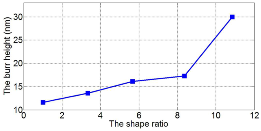
The effect of chip interference on the burr height at different cutting depths.
Effect of included angle of diamond tool
Through the analysis of cutting theory, the chip interference is an apparent factor affecting burr height and the micro V-grooves cutting with single-step cutting is typically non-free cutting. The reason is that both sides of the chip, which were cut synchronously by two cutting edges of diamond tool, extrude with each other. Therefore, how to reduce the level of chip interference becomes the key point to solve this problem.
From the analysis of shape ratio ε in the above section, the included angle of V-shaped tool influences the burr height as well. Figure 6 shows the inversely proportional relationship between the shape ratio and the included angles while the cutting depth is 10 µm with single-step cutting process. Hence, the increasing included angle of V-shaped diamond tool decreases the level of chip interference and the burr height. Figure 7 illustrates the different stress states of undeformed chips. The extrusion forces from both sides of chip, which squeeze the chip face to face, decrease in order when the included angle increases from 70.5° to 120°, and the undeformed chip shape is closer to the free type with the increase in the included angle. The above analysis implies that larger included angle can reduce the level of chip interference and burr height of micro V-grooves effectively.
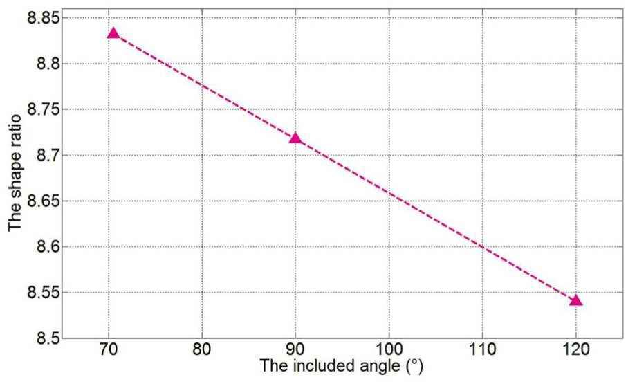
The relationship between shape ratio and included angles.
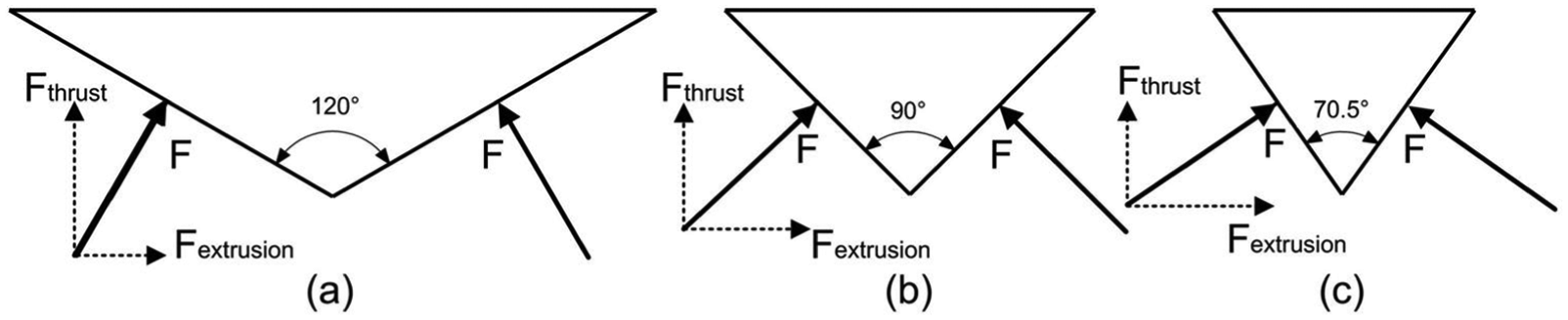
The stress states of undeformed chips with the different included angles.
The experiments were carried out to verify the above analysis. The V-shaped tools with different included angles of 70.5°, 90° and 120° were adopted while the spindle speed was 300 r/min and the cutting depth was 10 µm. Figure 8 shows the experimental results which agree well with the above analysis, and the included angle of V-shaped tool has great influence on the burr height of micro V-grooves. As the V-shaped diamond tool’s included angle increases, the burr height is reduced apparently.
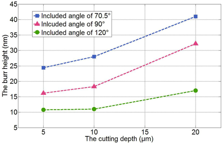
The influence of included angles on the burr height with cutting depth of 5, 10 and 20 µm.
Experimental results of chip interference and process optimization
From above all, the multi-step cutting process can acquire better surface quality than single-step cutting process, which possesses the similar influence on the burr height as larger included angle of diamond tool. In this part, the influence of the multi-step cutting process on the burr height of micro V-grooves is investigated with the material of electroplated copper.
The cutting experiments were carried out with single-step cutting depth of 4 µm and two-step cutting depth of (2 + 2 µm), respectively. The chip features in the two-step cutting experiment were observed by scanning electron microscope (SEM) and shown in Figure 9(a) and (b), respectively. Figure 9(a) shows that serious wrinkles exist on the back of chips in the first step cutting due to the chip interference and extrusion forces during the cutting process, but the back of chip in second step cutting is smooth because the undeformed chip morphology is closer to free type. That is to say, the chip in the second step cutting of the two-step cutting process suffers from slighter squeezing force and weaker chip interference than the single-step one, so does the surface of micro V-grooves. The burr height of micro V-grooves machined in the two-step cutting process is 14 µm which is lower than the burr height of 16.2 nm by single-step cutting. It is found that the final chip morphology can reflect the surface quality of micro V-grooves, and multi-step cutting process can reduce the burr height of micro V-grooves and improve the surface quality significantly.
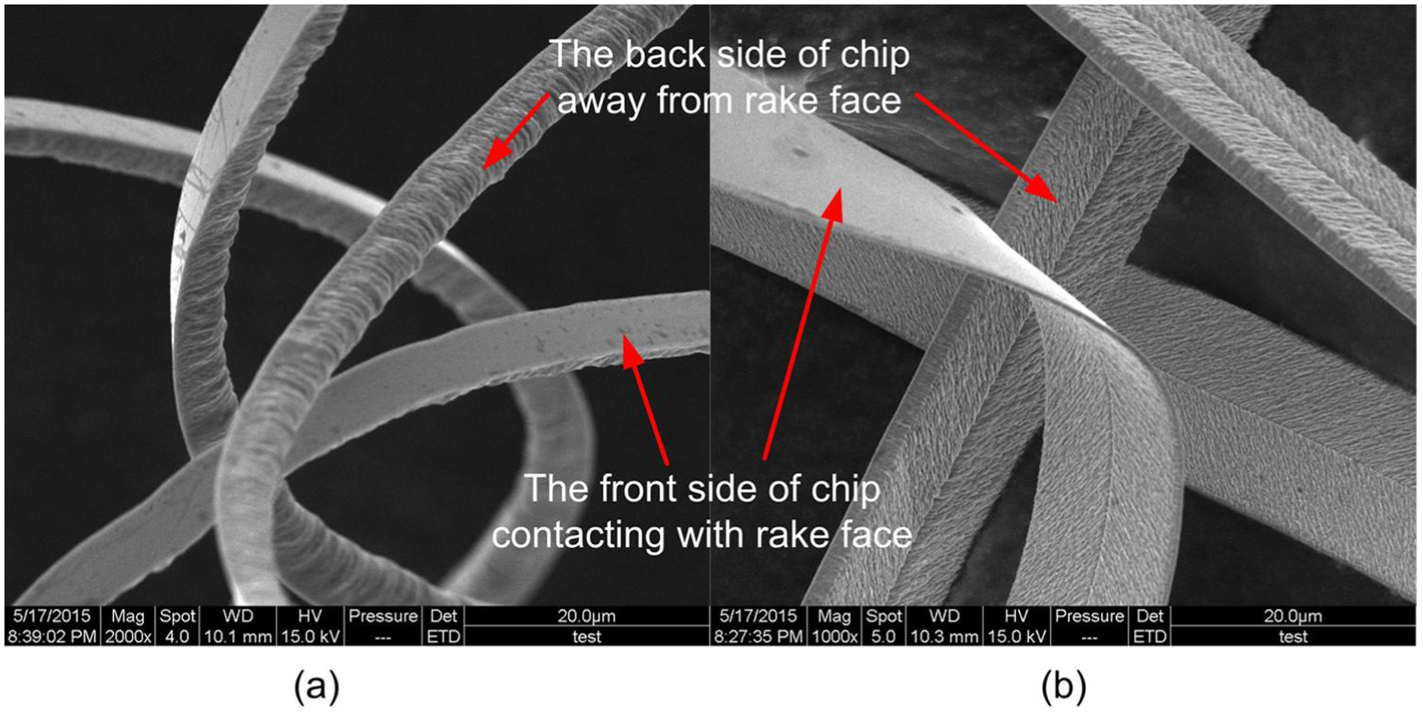
SEM photographs of chips in two-step cutting process: (a) the chip morphology in the first cutting and (b) the one in the second cutting.
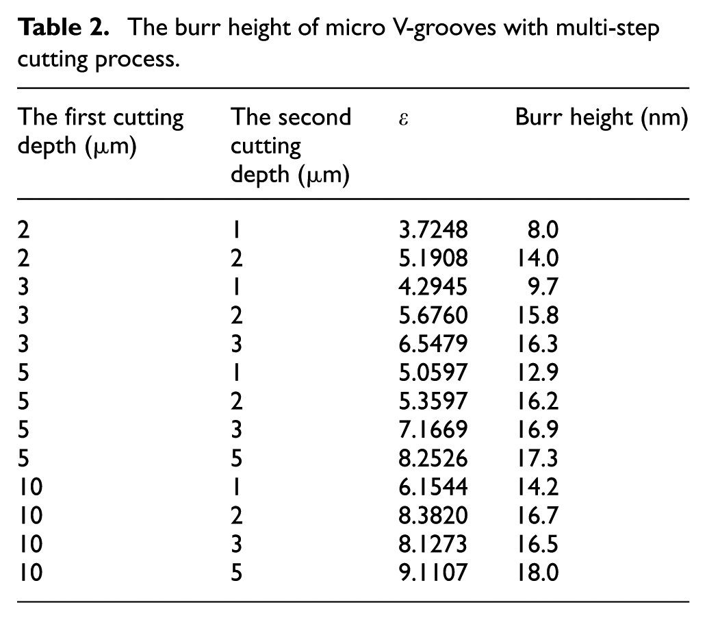
The selection of depth for the final step cutting is also a key point involved in the multi-step cutting process. In this part, the optimization of cutting parameters for two-step cutting process has been explored in the following cutting experiments, where the first step depth was 2, 3, 5 and 10 µm with the second step depth of 1, 2, 3 and 5 µm, respectively, while spindle speed was 300 r/min. The burr height was tested by stylus profiler, as shown in Table 2. It is found that the burr height has positive correlation with the first step depth and the second one. The relationship between the burr height and the first step depth can be found when the second step depth is 2 µm, where the smaller final depth gets better improvement effect on the burr height. The main reason should be that the final step chip thickness of 1 µm covers the burr generated by last step cutting. There is still the possibility that the depth less than 1 µm can acquire smaller burrs, but undersized cutting depth would not be proposed due to the cutting system stability and resistance to vibration. Therefore, the recommended final step cutting depth should be 1–2 µm which can consider both the burr height and the cutting system stability.
The burr height of micro V-grooves with multi-step cutting process.
According to the optimal cutting parameters, the continuous micro V-grooves (micro-prism array) were achieved with two-step cutting process where the cutting depth for the first and second step was assigned to be 18 and 2 µm, respectively. The micro-prism array on the workpiece was imprinted on the polyethylene terephthalate (PET) film with photo resist which can be solidified under the exposure of ultraviolet (UV) radiation. With the cutting experiment and UV-based imprint process, good consistency was obtained for micro-prism arrays on the workpiece and the PET film, which is shown in Figure 10. There are no apparent burrs of the micro-prism array both at the top of the workpiece and at the bottom of the PET film. Thus, the final step depth of 1–2 µm is reasonable for the multi-step cutting process, which can reduce the burr height and possess good cutting performance.
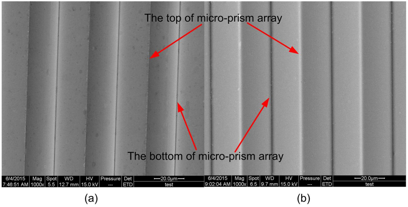
SEM photographs of micro-prism array with pitch of 40 µm: (a) the micro-prism array machined on the workpiece and (b) the micro-prism array imprinted on the PET film.
Conclusion
In this article, the influences of cutting parameters on the burr height during diamond turning of micro V-grooves is investigated from the perspective of chip interference, such as cutting depth, the included angle of V-shaped diamond tool and the multi-step cutting depth. Micro-prism array with pitch of 40 µm was successfully achieved on the electroplated copper workpiece with two-step cutting process. Based on the experimental results, the conclusions can be presented as follows:
The burr height has positive correlation with the material shape ratio ε which presents the level of chip interference. That is to say, the burr height has positive correlation with the cutting depth, but negative with the included angle of the V-shaped diamond tool.
The multi-step cutting process can reduce the burr height of micro V-grooves due to the small material shape ratio ε in the final step cutting.
The optimal final cutting depth for electroplated copper is recommended to be 1–2 µm during the multi-step turning of micro-prism array, which can reduce the burr significantly and possess good cutting stability.
Footnotes
Declaration of conflicting interests
The author(s) declared no potential conflicts of interest with respect to the research, authorship and/or publication of this article.
Funding
The author(s) disclosed receipt of the following financial support for the research, authorship, and/or publication of this article: The research was supported by National Science and Technology Major Project of High-end CNC Machine Tools and Basic Manufacturing Equipment of China (Grant Number 2011ZX04004–021).