
Abstract
Nimonic C-263 is predominantly used in the manufacturing of heat susceptible intricate components in the gas turbine, aircraft, and automotive industries. Owing to its high strength, poor thermal conductivity, the superalloy is difficult to machine and causes rapid tool wear during conventional machining mode. Moreover, the unpleasant machining noise produced during machining severely disrupts the tool engineer’s concentration, thereby denying a precise and environment friendly machining operation. Hence, close dimensional accuracy, superior machined surface quality along with production economy, and pleasant work environment for the tool engineers is the need of an hour of the current manufacturing industry. To counter such issues, the present work attempts to compare and explore the machinability of two of the most popular machining strategies like minimum quantity lubrication (MQL) and cryogenic machining process during turning of Nimonic C-263 work piece in order to achieve an ideal machining environment. The machining characteristics are compared in terms of surface roughness (SR), power consumption (P), machining noise (S), nose wear (NW), and cutting forces (CF) to evaluate the impact of machining variables like cutting speed (Vc), feed (f), and depth of cut (ap) with a detailed parametric study and technical justification. Yet again, an investigation is conducted to compare both the machining strategies in terms of qualitative responses like chip morphology, total machining cost, and carbon emissions. The study revealed that cryogenic machining strategy is adequately proficient over MQL machining to deliver energy proficient and gratifying work environment for the tool engineers by reducing the cost of machining and improving their work efficiency.
Keywords
Introduction
Nickel and its alloys are used in an extensive range of engineering applications such as manufacturing critical components used in aircraft, gas turbine applications, nuclear plants, naval applications, automotive applications due to their unique set of mechanical properties, and excellent ability to withstand extreme temperature. 1 It has become a complex task to machine these superalloys to a precise and accurate levels pertaining to higher hardness and strain-hardening. Currently, various Nickel based superalloys viz. Inconel, Titanium, Nimonic, etc. which possess unique combinations of properties, have been evolved for diversified applications. Nimonic, is one of such superalloys, which finds wide application in fabrication of intricate exhaust section parts in aerospace, automotive sector due to its ability to withstand and possessing unique set of properties at elevated temperatures. Generally, the alloy contains 45% Nickel and 25% Chromium with an additional amount of Cobalt, Titanium, and Aluminum.
Nimonic C-263 is amongst one grade of such superalloy series and serves a unique set of properties like excellent fatigue strength, creep resistance, high hot hardness, thermal stability, better yield strength, ductility. 2 Over the years, turning has evolved as an effective and precise machining process that has captured the enormous attention of researchers worldwide to machine various grades of Nimonic workpiece. 3 The basic intention of the turning is to remove the material in a single turn, which is convenient in comparison with the complex and tedious grinding operations. However, the process come across some difficulties during turning of Nimonic C-263 superalloy, owing to poor thermal properties and the tendency of strain hardening along with the formation of rough particles in structure during machining. 4 Furthermore, the Cobalt element from this alloy undergoes precipitation hardening which ultimately increases the strength and hardness of the material. Additionally, the development of built-up-edges (BUE) during machining of Nimonic C-263 worsens the surface integrity which causes rapid failure of the tool. To address such issues, various machining strategies and environments have been suggested by researchers.
Researchers globally have made ample efforts through numerous machining strategies for improving the efficiency of the turning operations.5–9 The use of coolants and lubricants over the cutting zone decreases the cutting temperature significantly in the machining areas. The application of coolants decreases the friction at the work-tool interface and takes away the heat produced at the machining zone. Minimum quantity lubrication (MQL) is one of the exclusive lubrication systems that is used for most of the hard-to-cut materials. In this, an aerosol is sprayed in a minute amount (10−100 ml/h) which is formed when cutting fluid is atomized with compressed air and directed on the machining zone.8,9 The process brings significant improvement in surface integrity, tool life, minimizing cutting temperature, and mechanical vibrations. Dhar et al. 10 studied the impact of MQL machining on the surface roughness, chip formation, cutting temperature during turning of AISI 1040 steel and observed significant improvement on the machining characteristics when compared to dry turning. For this reason, MQL used widely in recent years making it more valuable amongst all machining strategies of turning owing to its sustainability in regards to its economic and ecological value.11,12 However, a study reported Yıldırım et al. 13 stated that the lubrication and cooling ability of MQL is poor in some cases. The excessive heat generated at the machining zone may over temper a few alloys and oil used in MQL is always at greater fire risk compared to water-soluble flood coolants. The excessive heat generated due to friction at the machining zone causes a rise in a temperature at the cutting zone which leads to the softening of the cutting tool. 14 There are numerous studies which depict the consequences of softening of cutting tool viz; rapid or progressive wearing, loss of surface integrity, and dimensional accuracy of the work material. Hence, it is crucial to avoid high cutting temperatures at the machining zone.15,16 Several researchers studied the MQL machining approach and substantial reduction is seen in cutting temperature during MQL machining when compared to dry machining.17,18 Sivaiah and Chakradhar 19 in one of their studies conducted on 17-4 PH stainless steel cleared that cryogenic machining reduced cutting temperature to 49% when compared with MQL machining. Apart from that, extra care must be taken to set up MQL as it is quite a sensitive process compared to flood cooling or cryogenic cooling. The nozzles used for MQL need to be pointed at the machining zone properly as the amount of coolant used is already less leading to raise the tooling cost of the setup. Additionally, MQL is not very much compatible for deep hole drilling and for really hard-to-cut materials like titanium and nickel-based alloys. 20
Cryogenic machining is an important machining strategy which addresses the most common issues of metal cutting. Generally, the cutting fluids being used in most of the mechanical industries are mineral oils or water-based soluble oils. These cutting fluids cause ecological damage and threat to the work safety standards. Usage of these oils is hazardous for the operator’s health and also affects the rate of productivity. To counteract such negative effects, a sustainable manufacturing strategy such as cryogenic machining has been proposed by several researchers.21–23 Recently, numerous studies reported the adoption of cryogenic treatment to attain the enhanced machined surface and flank wear reduction during the turning process.6,13,24,25
Several aspects other than machining strategies play an important role in the effectiveness and productivity of the operation. The machining parameters viz; cutting feed, spindle speed, and cutting depth which have dominant effect over the surface integrity, tool life, and ultimately an economy is studied widely. Meddour et al. 26 showed the impacts of input parameters such as cutting feed, nose radius, depth of cut, spindle speed on the cutting forces, and surface roughness during hard turning on hardened AISI 52100 steels with ceramic inserts. The results showed that the depth of cut has a dominant effect on the cutting forces. However, the nose radius and feed have a considerable impact on the surface roughness. Surface roughness is an important consideration that influences the fatigue life, corrosion resistance, wear mechanism, and also tribological properties of the machined surface. Moreover, an excellent surface finish is achieved using wiper-coated carbide inserts compared to conventional inserts.27,28 Tool wear is also an important aspect in hard turning as it heavily influences surface integrity, dimensional exactness, induced stresses and ultimately, the tool life. 29
Along with these studies, several other studies attempted to sustain the machining environment by reducing the environmental hazards and disturbances during machining. In this direction, various studies highlighted the deleterious effects of machining noise produced which is an important social matter that directly influences human health.30,31 Bolaji et al. 32 explored the primary sources of noise pollution during manufacturing of various components. The study revealed various physiological and psychological impacts on workers and their possible remedies. The power consumption during any machining and its optimization has also become a very interesting topic in recent years.33–35 The power consumption during turning depends upon various parameters viz; type workpiece material, tool sharpness, machining environment, etc.
An extensive review of past works pertaining to the various machining strategies involving turning clearly indicates that MQL and cryogenic machining are the two most prevalent techniques adopted by the researchers recently. Both the techniques are widely used to enhance the tool life, machined surface quality, and delivering a satisfying work environment.6,13,20,23–25,36 However, a limited number of works have been reported to sustain a machining environment.30–32 Moreover, the technical cause and scientific aim behind the same still remain imprecise. The toxic emissions coming out from the machines during machining have not been handled properly to reduce the emissions. It is also observed that no work has been reported till now, which attempts to evaluate the sustainable machining measures like power consumption and machining noise produced during machining along with the conventional machining parameters. Mostly, researchers have evaluated common machining measures like surface roughness, flank wear, and cutting forces individually. Therefore, effort must be made to compare and evaluate the effectiveness of both the advanced strategies.
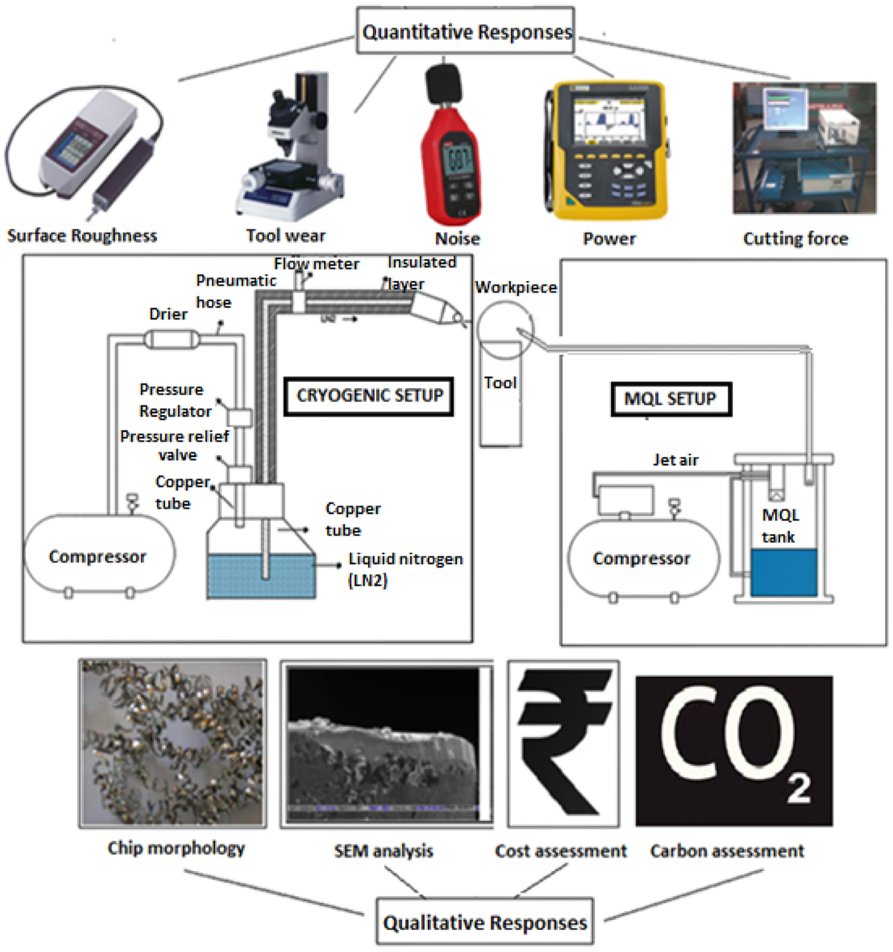
In view of this, the present work attempts to compare and analyze the effectiveness of MQL and cryogenic machining strategies through response variables viz. surface roughness, power consumption, machining noise, tool wear and cutting forces during machining. The turning is performed on Nimonic C-263 alloy workpiece by using multilayer-coated carbide cutting inserts under a cryogenic machining environment and in a MQL setup. Taguchi’s L27 orthogonal array is used to evaluate the influences of important machining parameters viz. speed, feed, and depth of cut on response measures during machining. A detailed parametric study along with a scanning electron microscope (SEM) analysis is conducted to analyze the outcomes of the parameters on the performance measures. Finally, machining strategies are compared in terms of chip morphology, cost estimation, and carbon emitted during both techniques. Figure 1 represents the schematics of the proposed work.
Schematic representation of current study.
Experimental procedure
In this work, spindle speed (Vc), cutting feed (f), and depth of cut (ap) are with three level of variations (lower-medium and upper) selected as the input parameters based on the extensive literature review.3,13,24–26 It is reported that Taguchi’s experimental design provides cost-effective, improved quality, and robust design solutions.24,37 The technique is proficient enough to plan the experiments in a systematic way and extract maximum information from minimum experimental runs. Therefore, in this work, Taguchi’s L27 orthogonal array is used to evaluate the outcome of three important process variables viz; speed, feed, and depth of cut (Vc, f, ap) on performance measures such as surface roughness (SR), power consumption (P), machining noise (S), nose wear (NW), and cutting forces (CF). The workpiece selected for machining is Nimonic C-263 bars of length 150 mm and diameter 30 mm. The experimental details of this study are depicted in Table 1. The mechanical properties of Nimonic C-263 are shown in Table 2.
Experimental details of the study.
Mechanical properties of Nimonic C-263. 3
For MQL machining, a twin-nozzle MQL applicator is used to spray vegetable oil at the flow rate of 70 ml/h and 4 bar compressed air pressure via two different nozzles. The Lechler full cone spray nozzles of 2.5 mm diameter are used for projecting from less than 10 mm distance on the machining zone. Nozzle 1 is positioned at 110° to the cutting zone and nozzle 2 is projected at 90° angle to the horizontal line in the opposite direction of nozzle 1. The positive displacement pump is used to spray vegetable oil on the machining zone and a pressure regulator is used to maintain the pressure. Similarly, for cryogenic machining, Liquid nitrogen (LN2) is projected on the machining zone at 0.35 l/min at 4 bar pressure. LN2 is sprayed via a lechler brass nozzle of 1 mm diameter. This nozzle is directed over the machining zone at 70° angle to the horizontal line. Figure 2 shows the experimental setup for MQL and cryogenic machining respectively.
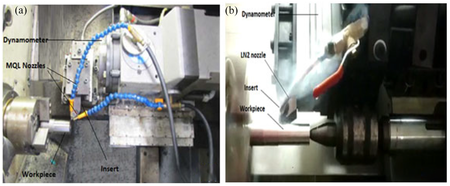
Experimental setup: (a) MQL setup and (b) cryogenic setup.
Measurement of responses
The experiments are conducted as per Taguchi’s L27 orthogonal array to record the values of the responses like surface roughness (SR), power consumption (P), machining noise (S), nose wear (NW), and cutting forces (CF). Each experiment is conducted twice and mean reading is considered for better accuracy.
Surface roughness measurement (SR)
The surface roughness (SR) measurement is carried out using Talysurf surface Mitutoyo’s (SJ-210) roughness tester. The readings were taken at four different points across its circumference with 90° and the average value, Ra in micron was noted as the final result in the Table 3. This is done to avoid manual or human error and to obtain a precise reading. 24
Comparative table of MQL and cryogenic machining results.
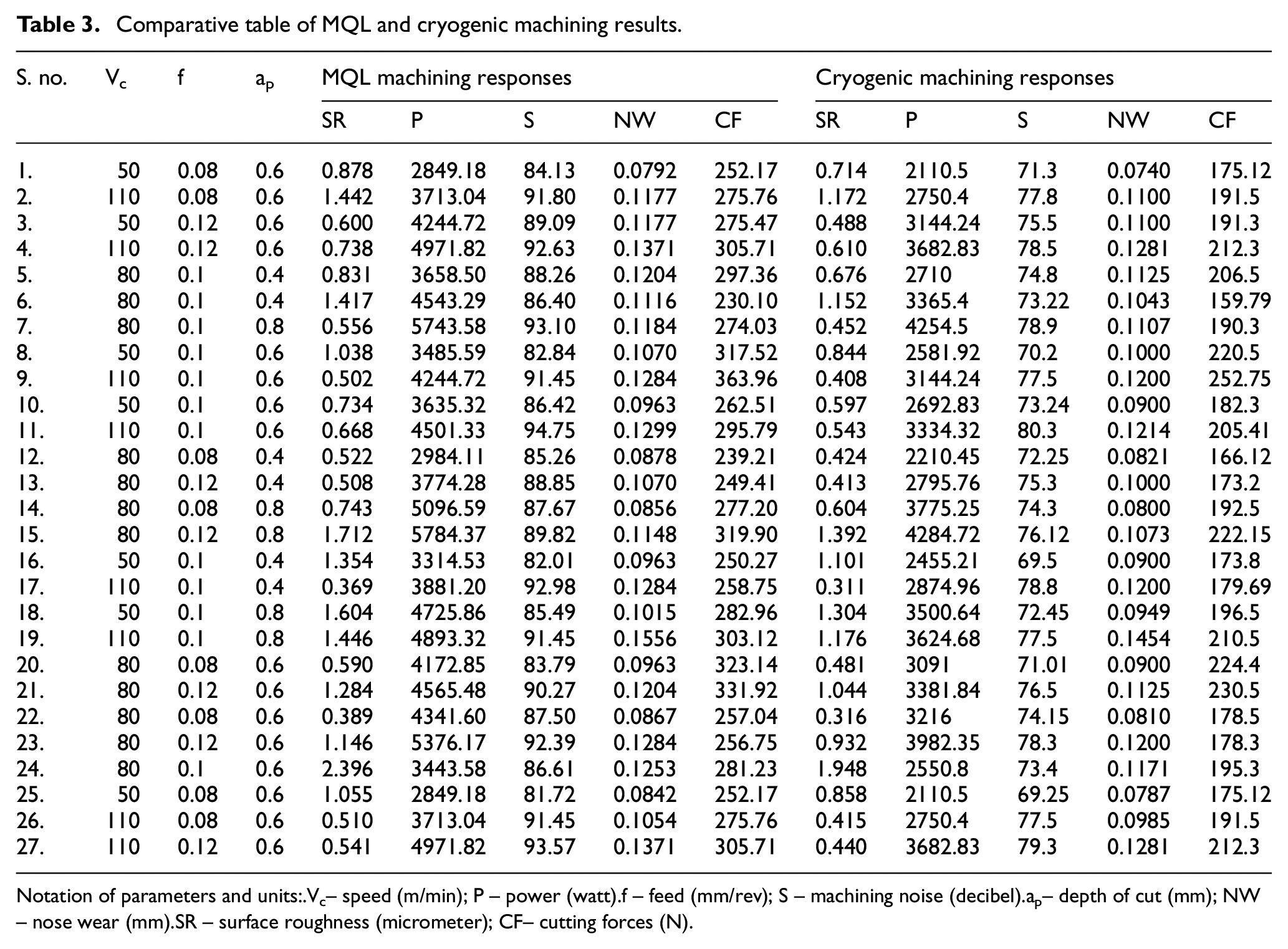
Notation of parameters and units:
Vc– speed (m/min); P – power (watt).
f – feed (mm/rev); S – machining noise (decibel).
ap– depth of cut (mm); NW – nose wear (mm).
SR – surface roughness (micrometer); CF– cutting forces (N).
Power measurement (P)
A Fluke 435 power analyzer (energy meter) device is connected to the electric panel of the CNC machine and used for the measurement of active and reactive power measurements. This gives the power consumption (P) for each turn in watts (W).
Noise measurement (S)
The noise intensity produced during machining (S) is measured in decibel (dB) by using Lutron SL-401 portable noise meter, switching off all the other laboratory equipment in an isolated workspace. Five reading of noise values are recorded, finally average of the reading are taken to get the most precise value of machining noise.
Nose wear measurement (NW)
The nose wear (NW) was measured by using Toolmaker’s microscope (Mitutoyo) and noted in terms of millimeters (mm). For this measurement, a difference of initial and final reading is taken under 10× magnification and noted as the final result.
Cutting force measurement (CF)
The cutting force (CF) was recorded by using tool dynamometer 5233A manufactured by Kistler having Dyno-Ware data acquisition system and noted in terms of newton (N). All the components of forces are plotted by using this software and average cutting force is recorded for each turn.
Results and discussions
Table 3 shows the Taguchi’s L27 orthogonal array with process parameters and obtained responses for two sets of experiments that is, for MQL and cryogenic machining. From Table 3, it can be visibly noticed that values of the all responses obtained through cryogenic machining are on the lower side as compared to the MQL machining, which indicates that cryogenic machining has performed better amongst the two techniques while cutting Nimonic C263 workpiece.
Parametric study of the responses
In order to extract further technical findings of the supremacy between both the machining strategies and to analyze the outcomes of the process parameters on the responses, a detailed parametric study is conducted on the responses by varying speed (Vc), feed (f), depth of cut (ap) in six steps. Figures 3 and 4 depicts the plots for the responses obtained through variation of parameters speed (Vc), feed (f), and depth of cut (ap) respectively.
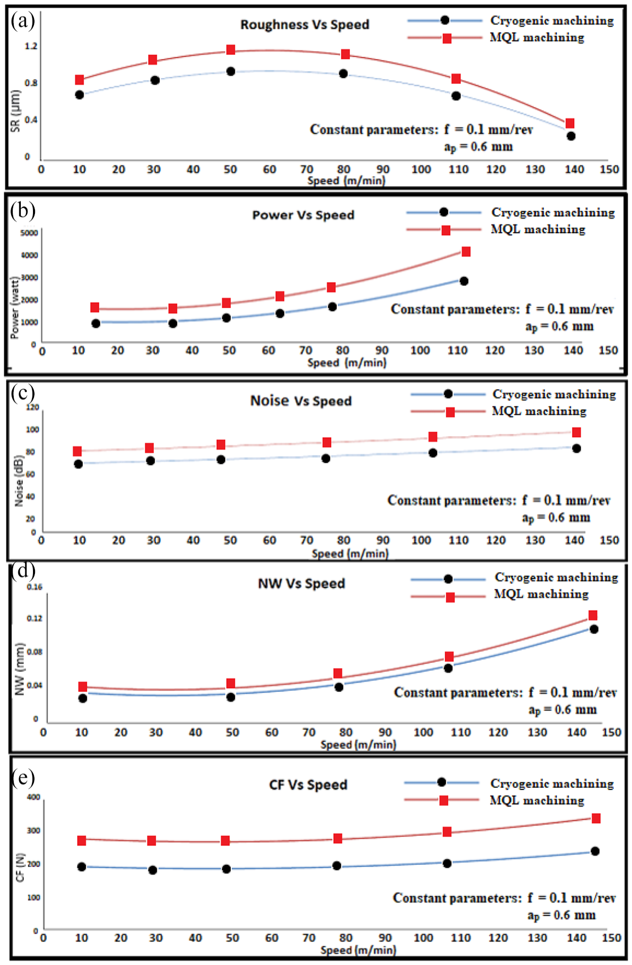
Effect of speed on responses: (a) roughness versus speed, (b) power versus speed, (c) noise versus speed, (d) NW versus speed, and (e) CF versus speed.
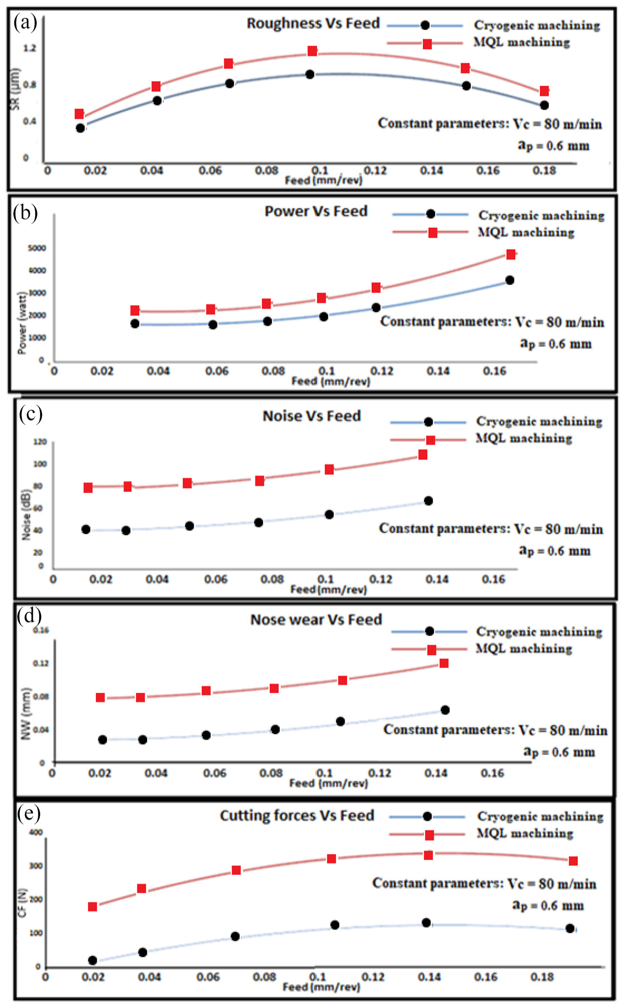
Effect of feed on responses: (a) roughness versus feed, (b) power versus feed, (c) noise versus feed, (d) nose wear versus feed, and (e) cutting forces versus feed.
Figure 3(a) illustrates the surface roughness values recorded by varying speed levels at constant values of feed and depth of cut for both the machining strategies. From the plot, it is observed that the surface roughness values are considerably smaller in the case of the cryogenic machined surface compared to the MQL machined surface. This is due to the inadequate lubrication during machining which causes more friction at the machining zone leading to the generation of irregular machined surface, resulting in poor machined quality. Moreover, surface roughness increases during initial speed levels however, beyond 50 m/min, Ra value was found to be decreasing upon increasing the cutting speed. This effect is due to the thermal softening of material owing to increased temperature at a higher speed which leads to superfluous subtraction of flaws and surface discontinuities. This mechanism results in the minimization of surface roughness values at higher speeds. Figure 4(a) shows that surface roughness increases when cutting feed is increased as increased frequency of vibration at higher cutting feed leads to poor surface finish. Additionally, if the cutting feed is increased beyond 0.10 mm/rev, surface roughness value exceeds the safer range for a certain feed range and then seems to be decreasing. Figure 5(a) shows that surface roughness increases when the depth of cut increases. This is due to the rubbing action between tool and workpiece which leads to rise in a temperature and increasing surface roughness value. A similar trend of results has been observed by previous researchers29,38 during their study.
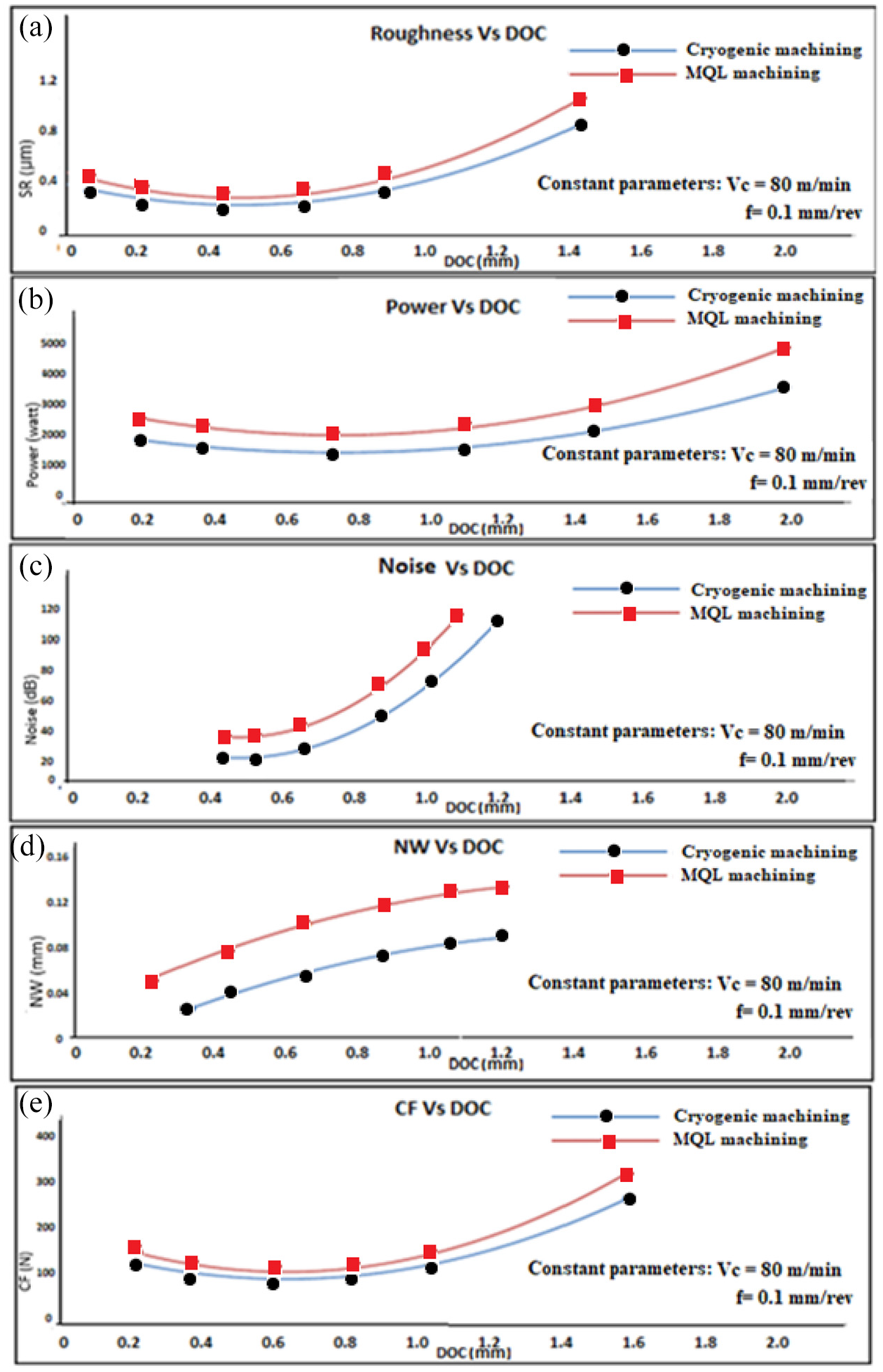
Effect of depth of cut (DOC) on responses: (a) roughness versus DOC, (b) power versus DOC, (c) noise versus DOC, (d) NW versus DOC, and (e) CF versus DOC.
Figures 3(b), 4(b), and 5(b) indicate that the power consumption is less in case of cryogenic machining compared to the MQL machining. This is due to the fact that during MQL machining, an additional pump is required other than the compressor to pump the fluid from a tank to the mixing chamber. On other hand, the only compressor is sufficient for spraying LN2 through a nozzle in cryogenic machining. This leads to more power consumption during all experimental runs of MQL compared to the cryogenic machining. Additionally, there is an increase in the power consumption with an increase in speed, feed, and depth of cut respectively. This is due to the fact that with increasing machining parameter values, the peak power required for free spindle rotations is increased. This is also supported by previous researchers. 39
Figures 3(c), 4(c), and 5(c) indicate that the machining noise for cryogenic machining is lesser in comparison with MQL due to the involvement of a lesser number of mechanical elements as well as production of less vibrational disturbances. These figures also portray that the machining noise increases with increasing values of speed, feed, and depth of cut. This is due to the fact that at higher machining parameters ranges, machine tool vibrations are higher that is, self-excited chatter vibrations or tool vibrations. The phenomenon is also supported by past studies. 40
The nose wear is accountable for the cutting-edge evacuation and has a larger impact on the dimensional precision of the workpiece. Figures 3(d), 4(d), and 5(d) show that nose wear is smaller in the case of cryogenic machining as compared to the MQL machining. This is due to the higher heat generation at the machining zone which deteriorates cutting tools considerably in the MQL machining in comparison with cryogenic machining. Figures also show that there is an increase in the nose wear with an increase in speed, cutting feed and depth of cut, however, nose wear values for cryogenic machining still remains below ISO 3658-1993 standard and acceptable for all machining parameter levels.
Figures 3(e), 4(e), and 5(e) show that cutting force values for cryogenic machining are lesser when compared to the MQL machining due to more wearing of tools during MQL machining. The sharpness of the tool is severely dented due to higher erosion, which in turn requires higher cutting force for cutting. Additionally, there is an increase in the cutting force with an increase in speed, feed, and depth of cut due to the fact that tensile residual stresses which are formed in the workpiece increases at higher levels of machining parameters leading to higher cutting forces. Similar results were also reported by Özel et al. 41 in their study.
Therefore, from a combined comparison of Table 3 and Figures 3 and 4, it is perceived that cryogenic machining strategy has overshadowed MQL machining strategy by delivering enhanced machinability characteristics for all the responses during cutting of Nimonic C263 workpiece.
Scanning electron microscope (SEM) analysis
A scanning electron microscope (SEM) (Leica/Stereoscan, S-440) analysis is conducted to analyze the post-machining changes on the workpiece, worn-out tool and chips. Figure 6(a) and (b) demonstrates the surface topography of the machined surface after MQL and cryogenic machining respectively. The SEM topography clearly shows severe damages on the machined surface during MQL machining in comparison to cryogenic machining. The Figure also depicts the presence of micro-pits and micro-cracks in the MQL surface which are much more intense than that of the cryogenic machined surface. The rise in temperature during machining causes the plastic flow of the material leading to the presence of significant feed marks. MQL machined surface appears to be rough due to less lubrication and more friction at the machining zone. On the other hand, the surfaces machined with cryogenic machining possess improved surface quality with less micro cracks and voids. This is also supported by previous studies. 24
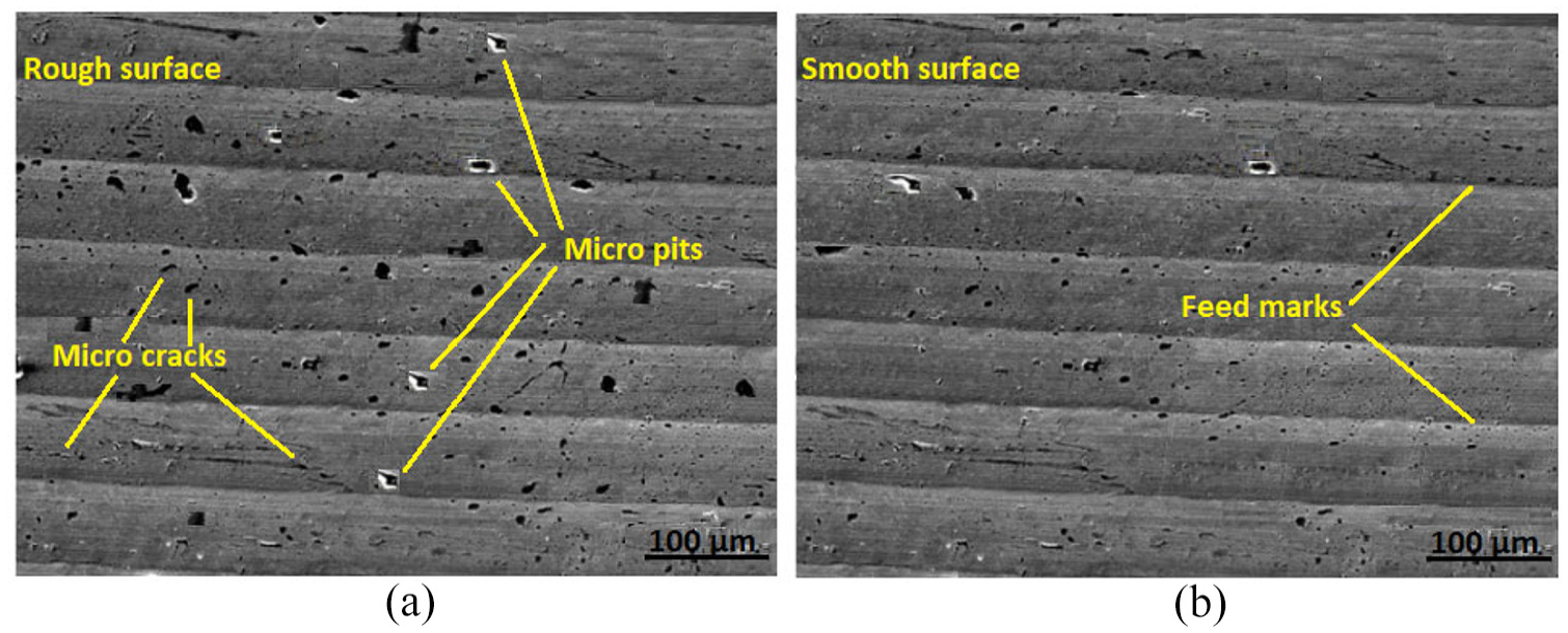
Surface topography of workpiece after: (a) MQL machining and (b) cryogenic machining.
Figure 7(a) and (b) shows the SEM images of the worn-out cutting inserts after machining under both machining conditions that is, MQL and cryogenic respectively. From these images, it is clear that tool wear is more in the case of MQL as compared to cryogenic machining. This is due to the fact that abrasion is the primary reason for the tool wear which leads to an erosion of the segment owing to less lubrication during MQL. The excessive heat at the contact zone causes eroded particles to adhere and diffuse leading to progressive wear. Whereas, cryogenic machining shows less erosion and abrasion of the cutting tool section. The inserts were found without any significant wear over cutting edge on machining under cryogenic environment. Similar results were recorded by Shokrani et al. 42 in their study.
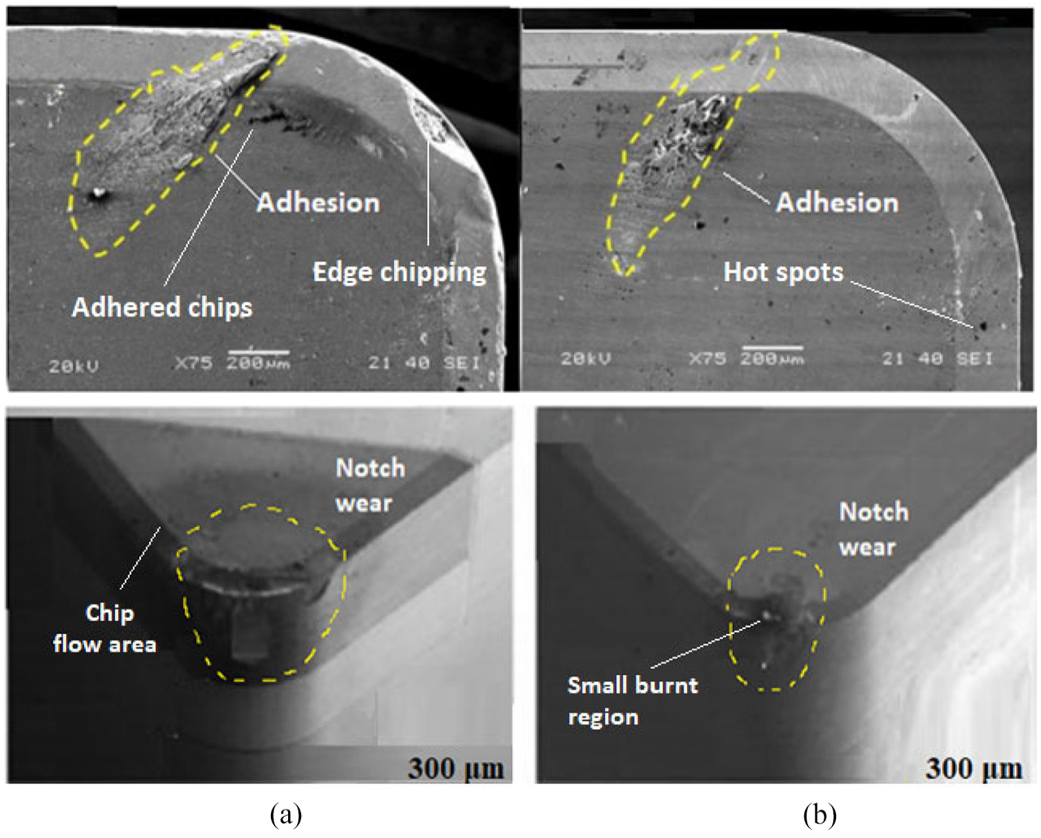
SEM micrographs of worn-out tools: (a) MQL setup and (b) cryogenic setup.
Chip morphology analysis
Chip morphology clarifies significant features of cutting mechanics and directly influences the surface integrity of machined components. In this study, the effects of both machining techniques are observed on the morphologies of chip of formation while keeping input parameters viz; speed, feed, and depth of cut constant. For this purpose, chips produced are studied with optical as well as SEM micrographs for both of the approaches.
Figure 8(a) and (b) shows the optical images of chips removed under MQL (a) and cryogenic (b) machining strategies respectively. It is observed that the chip formed during the MQL machining is tangled, whereas the chip formed during cryogenic machining is short and regular. The adhesive material detaching through the insert produced irregular voids over the rake face. Additionally, built-up edges over the cutting plane formed a rough back face and an irregular curvature of the chip. This effect proves that the wearing of the cutting tools can be reduced by using cryogenic machining. This is also supported by Musavi et al. 43 in their previous study.
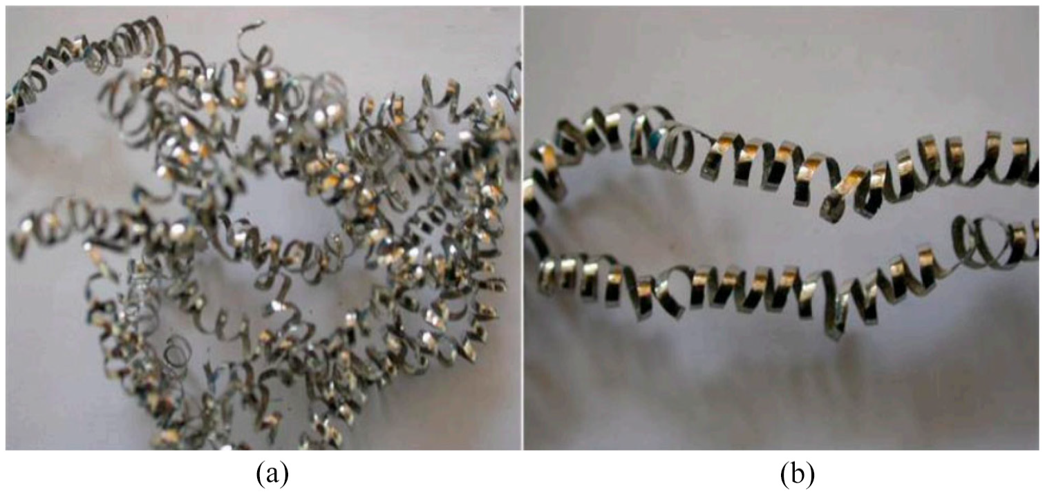
Optical images of chip formation: (a) MQL setup and (b) cryogenic setup.
Figure 9(a) and (b) shows SEM micrographs of the front and rear surface of the chips produced for MQL (a) and cryogenic (b) machining strategies respectively. Large scratches are observed on the rear surface of the chip due to excessive friction between the tool rake surface and the chip during MQL machining. This is due to the insufficient lubrication at the tool-chip interface. On other hand, very negligible scratches are observed on the chips formed by cryogenic machining. In the small frame, it is observed that the intensity of serration is high on the frontal chip surface of MQL machined chips whereas, small serrations are observed on the chips formed by cryogenic machining. The presence of shear crack leads to plastic deformation of chips owing to a higher temperature during MQL machining compared to the cryogenic machining. Similar observations were also reported by Thamizhmanii and Sulaiman. 44
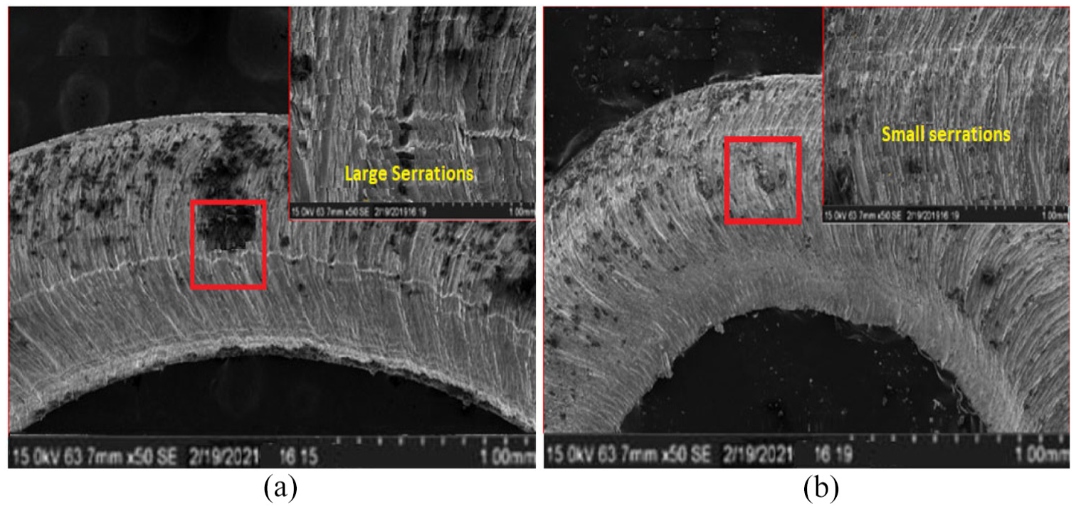
Frontal and rear micrographs of chip morphology: (a) MQL and (b) cryogenic setup.
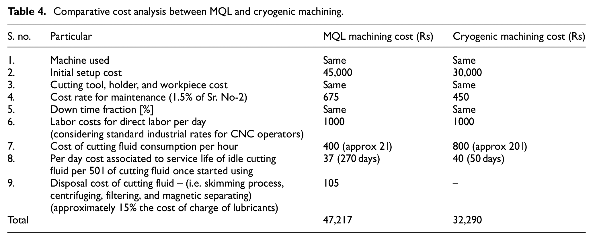
Cost assessment
Cost assessment is one of the vital qualitative parameters to evaluate the sustainability of the turning process. 26 The total machining cost for cryogenic turning and MQL turning are compared in this study. Following are some of the vital aspects considered for the cost assessment analysis.
The cost incurred during the machining process.
Energy and resources consumption.
Waste formation and its disposal along with the environmental impact.
The machining process cost involves all the costs associated with carrying out experiments viz; insert cost, maintenance cost, and labor cost. Both of these approaches have their own initial setup cost along with accessories. The calculations in this section are based on the machining under cryogenic and MQL approaches for the removal of 10 cm3 material. Table 4 shows the comparative cost analysis for cryogenic and MQL machining. To calculate the total cost for both of these approaches, all the sub-components of cost are added. The cost incurred for the machine, cutting tool, tool holder, workpiece, and downtime fraction is the same for both approaches and not considered in the total cost comparison. Initial setup cost is taken as per the standard quotations and maintenance cost is considered 1.5% of the setup cost. 45 The cost of energy consumption during each of the machining run that is, for removal of 10 cm3 material found to be almost uniform as energy-consuming devices like CNC machine, compressor is same for both of these approaches. For each of the experimental run, the new insert was used and hence, energy consumption for both approaches were found approximately uniform as there was no worn-out tool used for any run which ultimately would have consumed more electricity. The cost of cutting fluid is considered per hour depending upon the average consumption during MQL and cryogenic approach. The cost of idle cutting fluid is considered based upon their service life. 46 Table 4 shows that cryogenic machining incurs 31.61% lesser cost compared to MQL machining.
Comparative cost analysis between MQL and cryogenic machining.
Carbon emission
The carbon emitted during machining process is one of the key aspects to evaluate the sustainability of the process. The machining process comprises of carbons emitted from materials like worn out tool-workpiece, cutting fluid used, and other machining waste, etc. as shown in Figure 10.
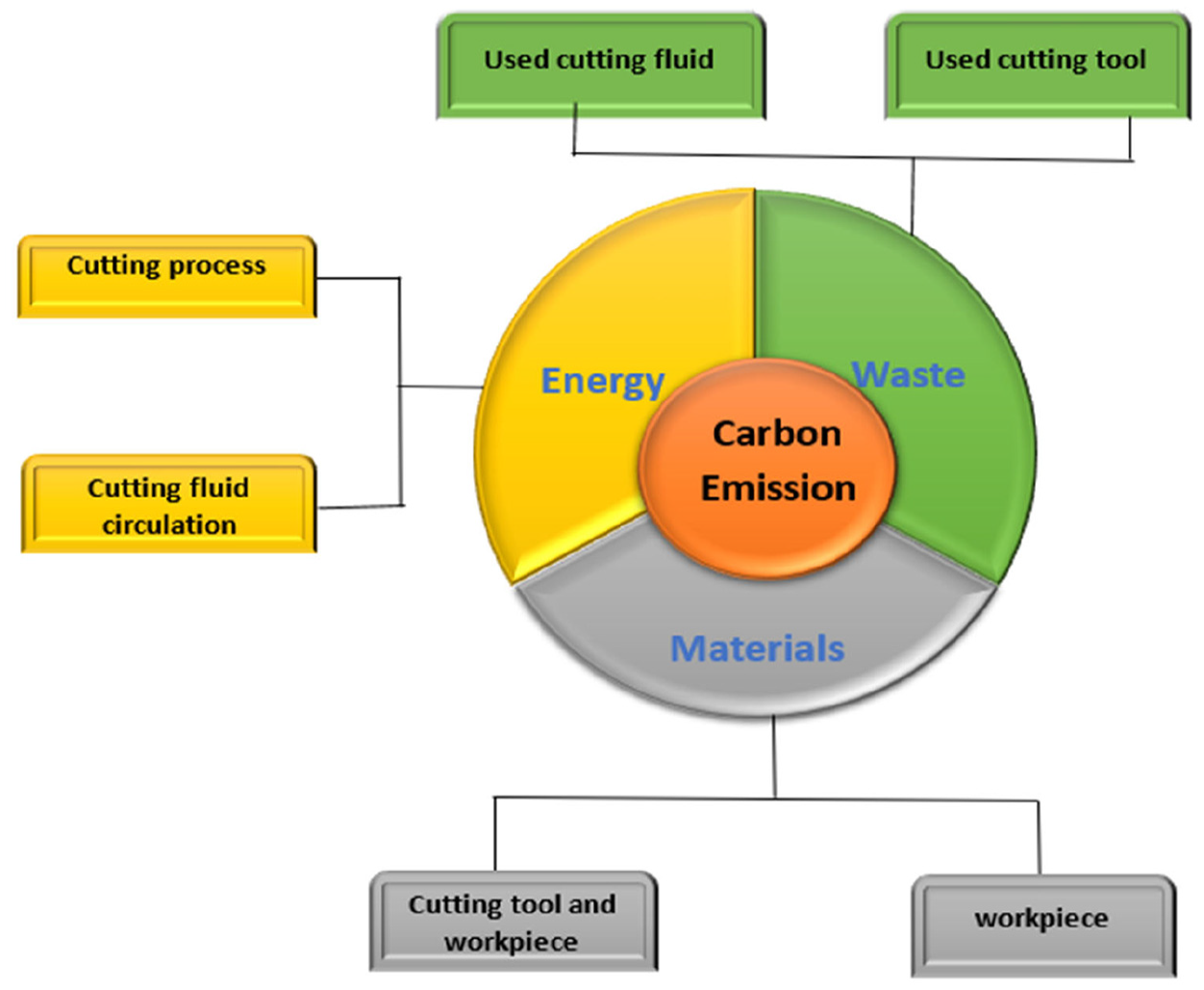
Components of carbon emission.
These resources contribute to carbon emission directly/indirectly and the total carbon emission (CEt) during machining is calculated by equation (1). 47

where, CEe is the carbon emitted due to energy, CEm is carbon emitted due to materials, and CEw is carbon emitted due to waste. This study aims to concentrate the most significant factor among these three aspects that is, CEe is the carbon emitted due to energy which contributes to almost 70% of the carbon emission, and hence other two aspects are not considered. 47
The present study compares the total carbon emissions (CEt) during MQL and cryogenic machining. For this comparison, 10 cm3 of material removal during both the machining technique is taken into consideration. The carbon emissions owing to the consumption of energy by machine tool during machining is calculated by using equation (2). 48

where, CEe, CFenergy, and ECMT are the carbon emissions owing to consumption of energy, carbon emissions factor, and power consumption by the machine tool respectively. In this equation, CFenergy comprises various components like power consumption during standby mode and machining mode. Ultimately, the power consumption is determined by multiplying it with respective energy consumption. The carbon emissions factor during power consumption is to be considered as 0.721 kg CO2/kWh according to the annual report of the Ministry of Power, India. 49 The average values of power consumption for all readings by machine tool (ECMT) are considered for CEe calculation that is, 4202.92 W for MQL machining and 3113.28 W for cryogenic machining. This clearly shows that CEe for cryogenic is much lesser that is, 2.24 kg of CO2 compared to the MQL machining which is 3.03 kg of CO2.
The in-depth assessment of qualitative parameters in terms of SEM analysis, chip morphology, cost assessment, and carbon emission for both the machining strategy indicates that cryogenic machining is capable enough to deliver a superior machined surface, cost effective, and sustainable machining environment over the MQL. Furthermore, a comparative analysis in terms of error bars for important responses for both the strategies are shown in Figure 11. These error bars are drawn considering the average values of responses obtained for all the machining runs during MQL and cryogenic machining approaches. The Figure clearly depicts that surface roughness during cryogenic machining is 18.7% lesser than MQL machining whereas, power consumption found to be 25.9% lesser in the cryogenic machining. Figure also shows that machining noise during cryogenic machining is 15.2% lesser and nose wear is 6.5% lesser compared to the MQL machining.
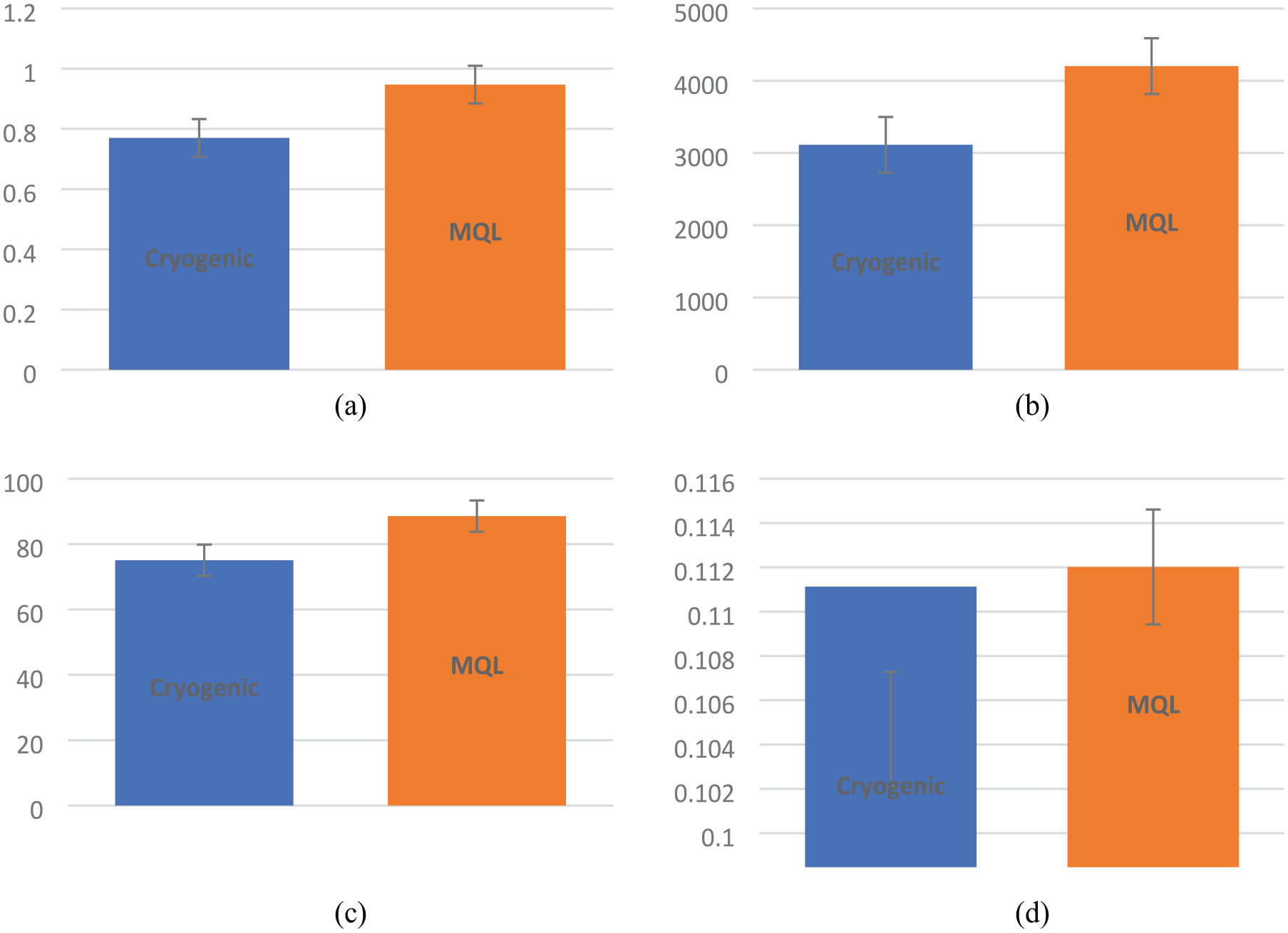
Comparative analysis of the responses during MQL and cryogenic machining: (a) surface roughness, (b) power consumption, (c) machining noise, and (d) nose wear.
Subsequently, the results obtained under cryogenic machining environment are found to be more prolific toward meeting the demand of energy efficient and eco-friendly machining and hence, it is decided to ascertain the optimum machining condition for the same. Accordingly, Taguchi’s Signal/Noise ratio (S/N) analysis is conducted to achieve the optimum machining condition, with an objective of achieving the lower-the-better criteria for the non-beneficial attributes of the cryogenic machining strategies.37,50–52 In this work, the optimum machining condition, to achieve the best processing quality as well as cost effective machining (obtained through S/N ratio-based optimization) is found to be, speed (Vc) = 80 m/min, feed rate (f) = 0.08 mm/rev, and cutting depth (ap) = 0.4 mm that is, experimental run no. 12.
Conclusions
The present study attempts to compare the MQL and cryogenic machining strategies in terms of quantitative (surface roughness, power consumption, machining noise, tool wear, and cutting forces) and qualitative (chip morphology, cost assessment, and carbon emission) measures to explore the machinability of Nimonic C-263 superalloy. Results clearly shows cryogenic machining strategy has outperformed MQL machining in terms of all measures to deliver an energy-efficient and eco-friendly machining environment for the tool engineers. Hence, it is concluded that cryogenic turning of Nimonic C-263 workpiece, has shown a huge potential to abolish with wet machining which is hazardous to both environments as well as tool engineers and correspondingly effectively limit the need of high energy consumption during machining. Following are some highlighted conclusions drawn from this study.
There is an improvement of 18.7% in surface roughness of the workpiece during cryogenic machining over MQL machining.
It is observed that cryogenic machining has 25.9% less power consumption compared to MQL machining.
The machining noise produced during cryogenic machining is 15.2% lesser compared to MQL machining.
The nose wear due to abrasion and diffusion is the main reason for tool failure and cryogenic machining battered MQL machining in the case of tool life by 6.5%.
The cutting force is also seen to be lesser by 30% in cryogenic machining amongst the two.
The study revealed that cryogenic machining incurs 31.61% lesser cost compared to MQL machining.
Total carbon emission is reduced by 26.7% in cryogenic machining when compared to MQL machining.
The study also reveals the optimal process parameters for cryogenic machining by using Taguchi’s S/N ratio as spindle speed of 80 m/min, feed rate of 0.08 mm/rev, and cutting depth of 0.4 mm.
This study supports the sustainability of cryogenic machining over MQL machining for Nimonic C-263 alloy considering its machinability and ecological aspects. However, the hybrid cryo-MQL process could be studied in terms of sustainability in the future.
Footnotes
Declaration of conflicting interests
The author(s) declared no potential conflicts of interest with respect to the research, authorship, and/or publication of this article.
Funding
The author(s) received no financial support for the research, authorship, and/or publication of this article.