
Abstract
It is well documented that surface structuring can improve the tribological performance of mechanical parts. For tooling, recent studies have focussed on structures applied to the rake face, the face in contact with the chip. This study investigates the impact of structures created on the flank face of the tool, which has not been widely explored. The flank face is an important area of focus because flank wear is a common end-of-life criterion for cutting tools. This article reports on the application of femto-second lasers to generate surface structures on the clearance face of the tool and their effect on tool–chip contact phenomenon and tool wear. A comparative study was conducted between machining with unstructured and structured cutting tools. Orthogonal cutting tests were performed over a range of cutting velocities, and flank wear, cutting power, compression ratio and tool–chip contact length were measured. The impact of a sticking and sliding contact was evaluated. Results showed a significant decrease in feed and cutting forces for a tool with flank-faced structures. The approach was a promising surface engineering innovation to improve the performance of cutting tools.
Introduction
The literature has many detailed examples of the ability of sub-millimetre scale structures to improve the tribological, optical and mechanical characteristics of interfacing surfaces. 1 These engineered and structured surfaces have shown to enhance the tribological properties of mechanical components. The application of structured surfaces on cutting tools has been investigated to improve the tool–chip interference phenomena on the rake face. Tables 1 and 2 summarise previous research on the type of structures, the method of structuring, the lubrication method and the cutting speed for both steel and aluminium. The results of studies in terms of percentage reduction in forces, temperature, tool wear and coefficient of friction are compared in Tables 1 and 2.
Rake face surface structuring in machining steel.
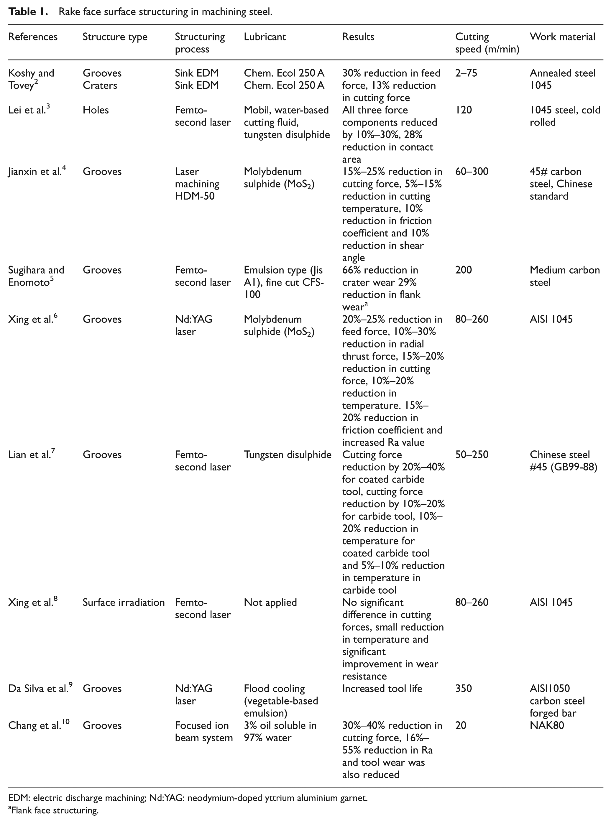
EDM: electric discharge machining; Nd:YAG: neodymium-doped yttrium aluminium garnet.
Flank face structuring.
Rake face surface structuring research for machining aluminium and titanium alloy.
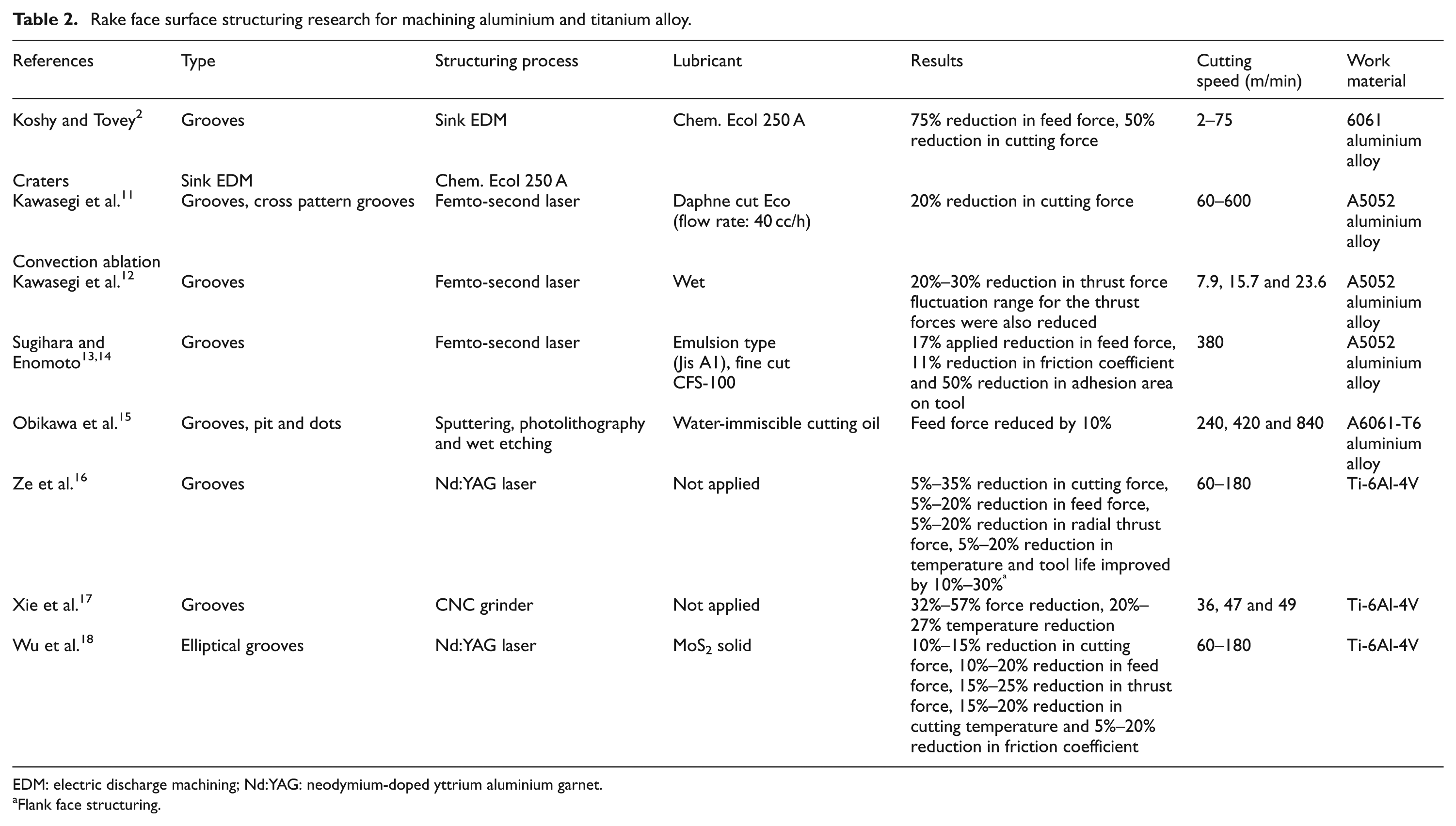
EDM: electric discharge machining; Nd:YAG: neodymium-doped yttrium aluminium garnet.
Flank face structuring.
Koshy and Tovey 2 used electric discharge machining (EDM) to create two different structure grooves and overlapping craters on the tool rake face at a distance 0.2 mm from the cutting edge. It was found that the crater structures were more effective than the grooved structures in reducing cutting forces. Overall, a 13% reduction in cutting force and a 30% reduction in feed force were noted when cutting steel. When aluminium was used as a workpiece material, a reduction of 75% in feed forces and 50% in cutting forces was observed. For both cases, a maximum cutting speed of 75 m/min was used. It was noted that the cutting speed range tested was too low for industrial machining of steel and aluminium alloys.
Lei et al. 3 utilised a femto-second laser to create micro holes on the rake face of the tool. These were filled with a solid (tungsten disulphide) and oil lubricant and were tested in dry machining and flood lubrication. Nearly 28% reduction in the tool–chip contact length was reported and up to 30% reduction in the cutting forces. It was proposed that the micro holes acted as reservoirs for the lubricant. The cutting velocity used for this experiment was 120 m/min.
Jianxin et al. 4 tested three different geometries of micro structure, created by lasers (type: HDM-50) on the tool rake face and reported a reduction in the cutting forces, cutting temperature and the coefficient of friction. They proposed that this reduction was due to the formation of lubricating film which was released from the rake face structure when filled with lubricant. In addition, it was suggested that the surface structuring on the tool rake face could decrease the tool–chip contact length. However, no empirical investigation on this was covered in this study. These results were produced for Chinese carbon steel (#45) as a workpiece and for the cutting speeds of 60–300 m/min.
Sugihara and Enomoto 5 suggested a reduction in crater and flank wear when two cutting tools (one with rake face structures and other with flank face structures) were separately used to machine medium carbon steel at a cutting velocity of 200 m/min. Structures were crated parallel to the cutting edge on both cutting tools. The distance from the cutting edge was not specified in their article. Xing et al. 6 also investigated the performance of structured tools. Their work used structuring on an Al2O3/TiC ceramic tool, and a workpiece of AISI 1045 hardened steel was used to test structures, at a cutting speed of 80–250 m/min. This study concluded that the structured tool was effective in reducing cutting forces, cutting temperature and friction coefficient at the tool–chip interface. It was also noted that crater wear was reduced significantly. However, increased surface roughness values were reported when structured tools were used.
Lian et al. 7 compared machining performance of a femto-second laser-developed soft-coated structured tool with an uncoated carbide structured tool. Cutting tests were performed on Chinese steel #45 over a range of cutting velocities of 50–250 m/min. It was concluded that the soft-coated structured tools were more efficient in reducing cutting forces and temperature. It was explained that this was due to the formation of a WS2 lubricated film released by soft-coated structured tool. Xing et al. 8 irradiated the tool rake face with a femto-second laser and carried out machining tests at a cutting speed range from 8 to 260 m/min with this tool. No significant results were reported in their study except that when high pulse energy was used, cutting temperature and tool wear resistance were improved. Da Silva et al. 9 used an neodymium-doped yttrium aluminium garnet (ND:YAG) laser to create micro grooves in different directions on tool rake face and proposed that the life of a cutting tool would be increased when structures were created perpendicular to the direction of the chip flow. However, no reporting was made on cutting forces and temperature. The cutting speed used for these experiments was of 350 m/min. Moreover, the wear mechanism of worn inserts was replicated through scratching with slurry, to compare the beneficial effects of laser structuring in machining. It was thus proposed that the performance of structured tools was not associated with an increased wear resistance. Chang et al. 10 used a focused ion beam (FIB) method and Kawasegi et al. 11 used Ti:sapphire femto-second lasers to create grooves on the rake face of a cutting tool. It was demonstrated that along with size and shape, the direction of created structures made a strong contribution to the reduction of cutting force. Both Chang et al. 10 and Kawasegi et al. 11 proposed that the cutting forces, surface roughness of workpiece 10 and friction coefficient 11 were greatly reduced when the structures were created perpendicularly to the chip flow direction. In contrast, structures created parallel to the chip flow direction significantly increased the cutting forces compared to a non-structured tool. It was thought that structures created perpendicular to the chip flow contributed to early chip curl over a rake face due to better lubrication. The cutting velocities used by both researchers, Chang et al. 10 and Kawasegi et al., 11 were in the conventional range for the given workpiece material which was NAK80 and A5052 aluminium, respectively. Kawasegi et al. 12 used femto-second laser to create micro and nano grooves on high-speed steel drill bit. These drill bits were tested in cutting experiments of aluminium alloy at a cutting speed of 7.9, 15.7 and 23.6 m/min. It was found that structured drill bits significantly reduced not only the thrust force but also the fluctuation range of the thrust. Furthermore, it was reported that direction of created structures with respect to cutting edge was also an influential in determining the effect of structures. It was found that the direction perpendicular to the chip flow was effective in reducing thrust forces.
Sugihara and Enomoto13,14 conducted experiments of face milling for an aluminium alloy revealing that surface structuring of cutting tools significantly improved the anti-adhesiveness and the lubricity properties of the tool–chip interface. It was also reported that a 50% reduction in an area of aluminium adhesion on tool rake face was observed with structured tools. 13 Obikawa et al. 15 investigated the cutting performance of micro-shaped surface structures on the rake face of coated tools. Techniques of spattering, photolithography and wet etching were employed to fabricate these structures. Structures were created at the distance of 100 and 150 μm from the cutting edge. Cutting velocities of 240, 420 and 840 m/min were used for the cutting tests in machining of A6061-T6 aluminium alloy. It was reported that as the structured size decreased, the structure reduced the frictional force and contact length more effectively. Similar results were obtained by Yuan et al. 19 and Suh et al. 20 for orientation and lubricating effects of micro grooves on sliding surface. Ze et al. 16 compared the performance of Nd:YAG laser rake face structured tool and a flank face structured tool with a non-structured tool while machining Ti-6Al-4V alloy. They reported that the rake face structured tools were more efficient in decreasing cutting forces and temperature, while flank face structured tools showed superior anti-wear ability. Xie et al. 17 tested the effect that different geometries of micro structures had on cutting temperature and cutting force. It was found that as the groove depth decreased from 149 to 25 μm, the cutting temperature decreased and the shears angle increased. It was also concluded that where high material removal rates were involved, tools with groove depth of 25 μm were more effective in reducing temperatures and cutting forces. The cutting speeds used in this study were of 36, 47 and 49 m/min. Wu et al. 18 developed three different tools: (1) micro-textured self-lubrication tool (SLT), elliptical structures were created on inserts and were filled with solid MoS2. 2) pulsating heat pipe (PHP) self-cooling tool (SCT), and 3) self lubricating and cooling tool (SLCT), a pulsating heat pipes (PHP) containing partially filled fluid were fixed on inserts and micro textured for lubricating were also created on tool, both PHP and structures were incorporated in SLCT. The performance of these three tools was compared to the conventional tool (CT) in terms of cutting forces and temperature, at a cutting speed of 60–180 m/min. It was found that all the developed tools were effective in reducing temperature and cutting forces, but the maximum reduction was with the SLCT.
It is clear from these studies relating to the tool–chip interface that micro structures have a positive effect on cutting performance. However, there are only two studies that investigate the influence of flank face structuring on tool–chip contact phenomena and tool life. Research presented by Sugihara and Enomoto 5 does not assess tool life, while Ze et al. 16 use Ti-6Al-4V as a workpiece material. This study carried out a comparative investigation of the effect of tool flank face surface structuring on tool–chip and focussed on tool–workpiece contact phenomena at different cutting speeds. Previous research has helped to develop the hypothesis that structures applied on the clearance face should have a strong and direct impact on tool wear, and reducing forces should have an impact in lowering power and energy demand.
Experimental details
Flank face structuring set-up
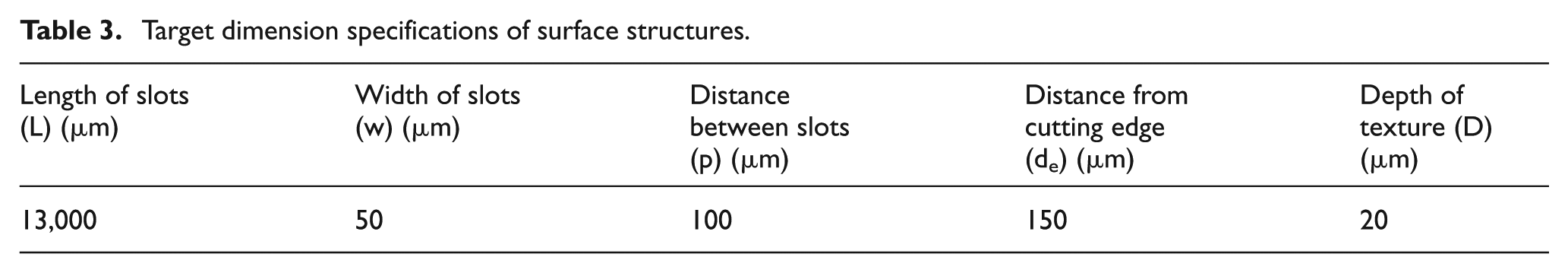
Structures were created on uncoated flat cemented carbide inserts (Sandvik TCMW 16T308 5015). Carbide grade 5015 represented a composition of 7% Co and 80% of WC with a grain size of 1.3–2 μm. Thermal conductivity of the carbide insert was 88 W/mK. A femto-second laser with the centre wavelength of 800 nm was used. It had a maximum repetition rate of 1 kHz and laser pulses of a width of 100 fs. The average pulsed energy of 1 mJ was used in this experiment. The energy stability was about ±12% of the average value. The laser spot size was 30 μm, and scanning speed was 10 mm/s. The processing conditions were established in an earlier study. 21 The experimental set-up for Ti:sapphire femto-second laser machining is shown in Figure 1. A computer-controlled translation stage was used to translate the cutting insert which was screw mounted on a fixture, perpendicular to the beam axis. Figure 2(a) and (b) shows the images of the structured fabrication on the cutting tool’s flank face. Dimension specifications of surface structures are presented in Table 3. These dimensions were established from the results of pervious research study on the assessment of structure geometry 22 and pilot cutting tests (Figure 3). From Figure 3, it is clear that a distance of 150 μm from the cutting edge is the best position to start structuring the flank face. Structuring nearer or further from the cutting edge produced worse results in terms of force reduction. Surface characterisation of the produced structures was carried out by three-dimensional (3D) white light interferometry (Figure 4). Based on the 3D white light interferometer results obtained at different locations on flank face structures, it was inferred that the quality and the size of created structures were consistence over flank face. On average, all the dimensions were made to ±5 μm. As all experiments were performed in air (i.e. at ambient condition without cutting fluid), all cutting inserts were washed in an ultrasonic vibrated tank with deionised water for about 10 min for the removal of debris.
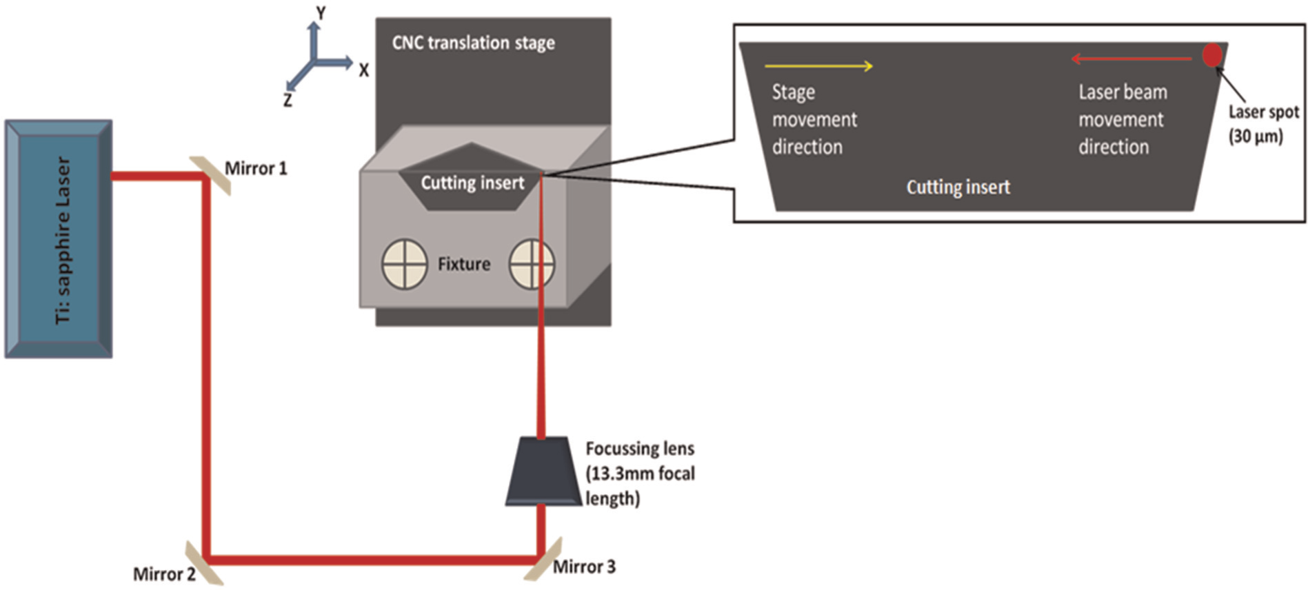
Set-up for femto-second laser machining.
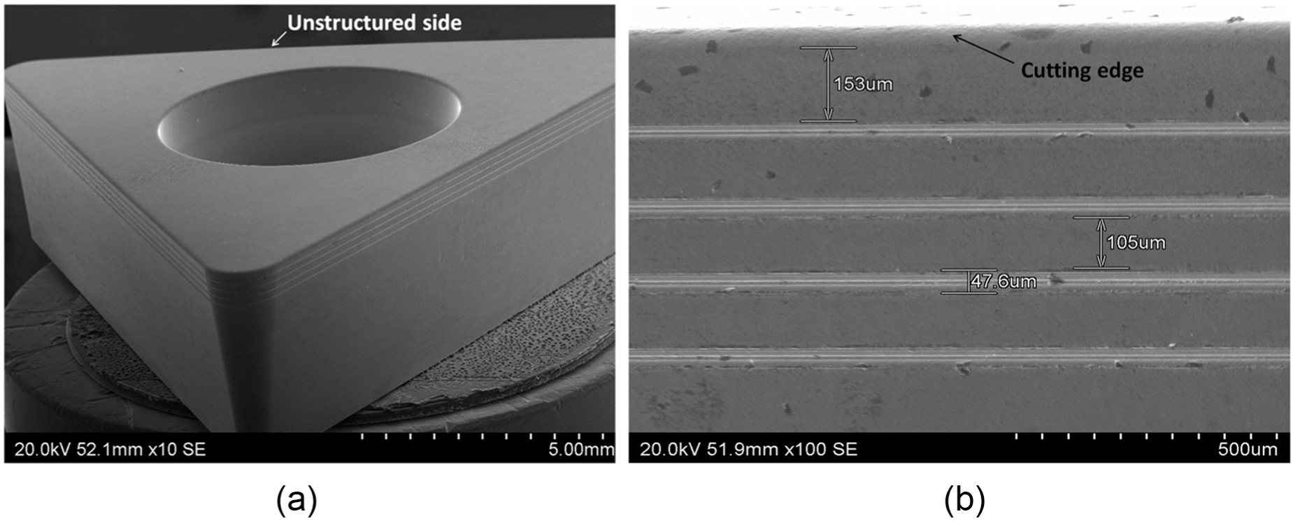
(a) SEM image of structured cutting insert and (b) enlarged image of the flank face of a cutting insert.
Target dimension specifications of surface structures.
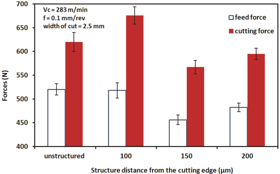
Cutting force data of pilot cutting test.
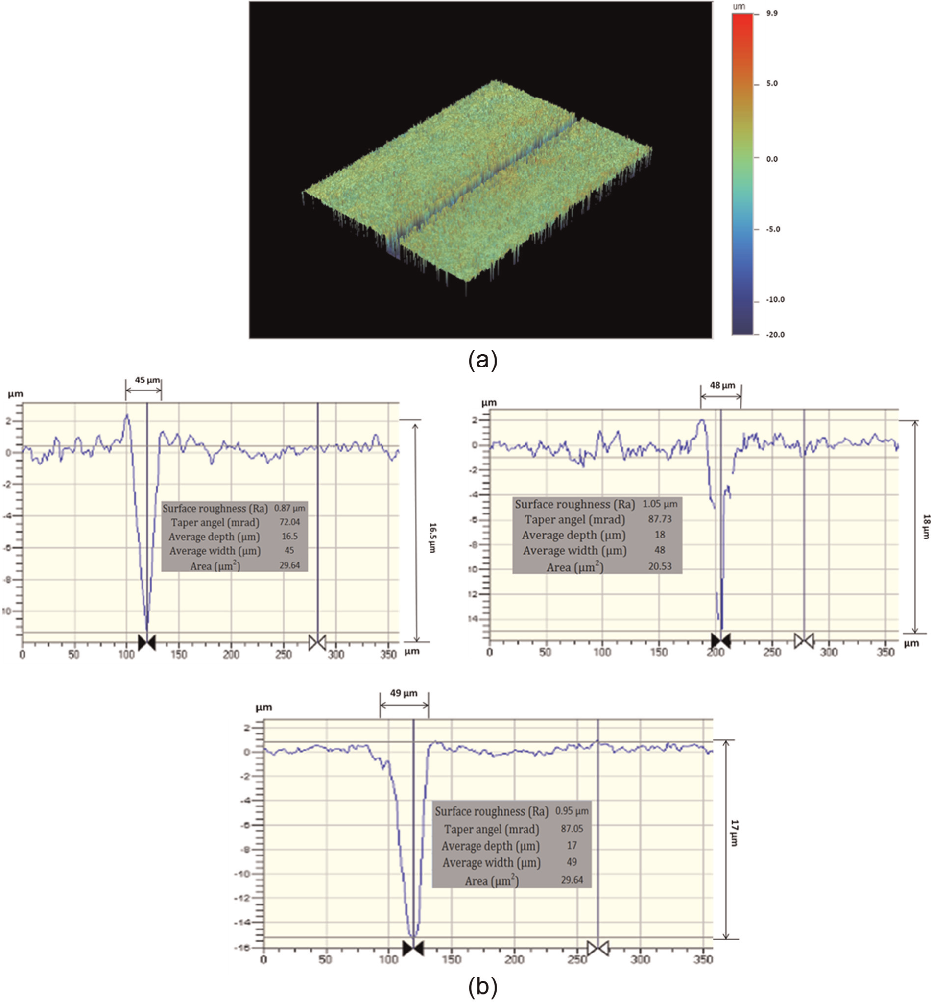
(a) 3D white light microscopy image and (b) cross section of the laser cut.
Machining set-up
AISI 4140 plain carbon steel (23.9 HRC) was selected as a workpiece material. The work material was in the form of a bar with an outer diameter of 200 mm. For orthogonal cutting, the work material was machined to a tube of a thickness of 2.5 mm. The diameter of the tube was kept reasonably large (200 mm) to reduce the effects of speed variation across the cutting edge. Inserts were mounted on a Sandvik STGCR 2020k-16 tool holder, which had a zero rake angle and 7° clearance angle. Four different cutting speeds were used (100, 198, 394 and 628 m/min) to test the performance of the structures. These speeds were selected to include recommended ranges from tool manufacturer’s specification. The width of cut was fixed by the thickness of the tube, and the feed rate was also fixed to 0.1 mm/rev. For each cutting speed used, results from a structured and an unstructured insert face were compared. A cutting compound, Trefolex, from Warren Bestobell was used as a lubricant and applied on the tool flank face. All the experiments were repeated.
Contact length was measured by observing scratch marks on scanning electron microscopy (SEM) images. As the tracks were not regular, an average value of contact length was established by measuring 10 different locations on the tool–chip contact area. Cutting forces were measured with a piezoelectric KISTLER dynamometer type 9263. An average value of force was calculated from the time-domain force trend once the forces had stabilised. An example of a force profile is shown in Figure 5.
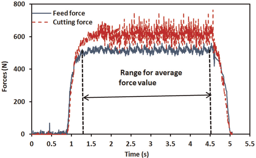
Time-domain force stabilisation for the cutting velocity of 198 m/min.
In addition, the temperature of the tool was also measured using an infrared (IR) thermal image FLIR ThermaCAM® SC3000. This camera could measure temperatures from −20 °C to 2000 °C with an accuracy of 2%. To capture the temperature profile generated on the tool rake face during machining, the camera was mounted at a distance of 0.4 m in a position such that it could capture thermal image of tool rake face clearly but safely (Figure 6). Stored images were analysed using ThermaCAM Researcher software using thermal emissivity for the tool material of 0.48 at 700 °C, as established from furnace measurement. The average temperature was recorded during cutting on paths as shown in Figure 7. The length of the path on each side was 1 mm and the distance from the cutting edge was also 1 mm.
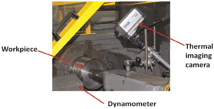
Set-up for machining.
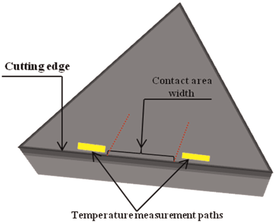
Temperature measurement locations.
Results and discussion
Cutting forces
Results for the cutting force and the feed force components were plotted against the cutting velocity in Figure 8(a) and (b), respectively. Increasing the cutting speed led to a decrease in both the cutting force and the feed force. As the cutting speed was increased, the work material was deformed because of the high strain rates in a narrow shear plane, which led to high temperatures in the primary deformation zone. The result is a thermal softening of the work material which causes a decrease in cutting and feed forces. The cutting force shows significant difference between the unstructured and structured cutting tools. A similar trend was observed for feed forces. On average, the reduction associated with the lubricated structures was 13% for cutting forces and 11% for feed forces. It was noteworthy that the structures on the flank face consistently led to a reduction of cutting forces for a wide range of cutting velocities (100–628 m/min).
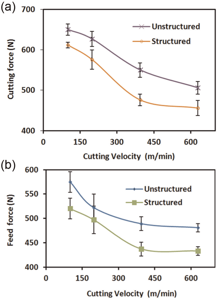
(a) Variation in cutting force with cutting velocity and (b) variation in feed force with cutting velocity.
This decrease in the feed force due to thermal softening produces an improvement in the rake face friction condition due to flank face structuring. For a zero rake angle of the cutting tool, feed forces are directly related to friction force on the rake face. Therefore, the feed force can be considered as a product of the shear strength of the chip material and the area of contact between the tool rake face and the chip (equation (1))

where Ff is the feed force, τ is the shear strength, Ar is the contact area on rake face, Lcr is the contact length on rake face and Wr is the contact width on rake face. Structured tools have significantly decreased tool–chip contact length (Figure 12), decreasing the frictional force and therefore the feed forces.7,16,18 While the cutting force is the result of shearing and friction process in cutting. 2 With reduced friction and high shear angles, structured tools result in lower cutting forces.
Compression ratio
The ratio between deformed and undeformed chip thickness is termed the compression ratio. In this study, the compression ratio was calculated by measuring the weight and geometry of the chip produced.23,24 For each experimental run, a chip length of 50 mm was selected and weighed. An average value used was based on 10 readings for each experimental run. Equation (2) was used to calculate the chip compression ratio

where λ is chip compression ratio, t2 is chip thickness (mm), t1 is undeformed chip thickness (feed) (0.1 mm), m is mass of a chip (g), ρ is density of workpiece (0.00775 g/mm3), l is length of chip (50 mm) and ap is depth of cut (2.5 mm).
The chip compression ratio has significant importance as it indicates the degree of chip deformation. The reduction in chip deformation shown in Figure 9 implies that flank face structured cutting tools produce a more energy-efficient process.
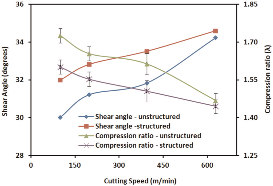
Variation of shear angle and compression ratio with cutting velocity.
This decrease in compression ratio is accompanied by an increase in shear angle which there by decreases the shear plane length (Figure 9). A small shear plane length results in high temperatures in a vicinity of the cutting edge. 25 An increase in temperature decreases the yield stress of the work material. This allows efficient cutting of the work material producing chips that are thin and move with high velocity over tool rake face.
Temperature
Figure 10 shows the temperature profile at a cutting velocity of 100 m/min for an unstructured cutting tool. Figure 11 shows the effect of cutting velocity on tool–chip interface temperature for structured and unstructured tools. The highest temperature at the tool rake face occurs for the unstructured tool. Overall, a 12% reduction in the tool–chip interface temperature was observed for the structured tool at lower cutting speeds. This reduction in temperature at lower cutting speeds is attributed to a decrease in the real contact area and thus the friction between the tool and the workpiece, due to the structures and the lubricant. High cutting speeds are associated with high cutting temperatures. Therefore, it can be inferred that ability of structures to reduce tool temperature is partially invalid at the speed of 625 mm/min where an increase in a temperature is due to a narrowing of shear plane near the cutting edge (Figure 9).
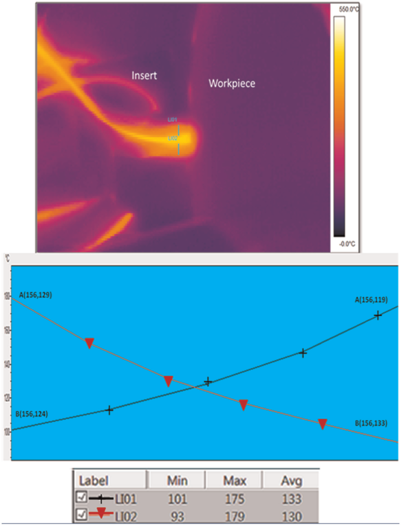
Temperature profile at cutting velocity of 100 m/min for unstructured cutting tool.
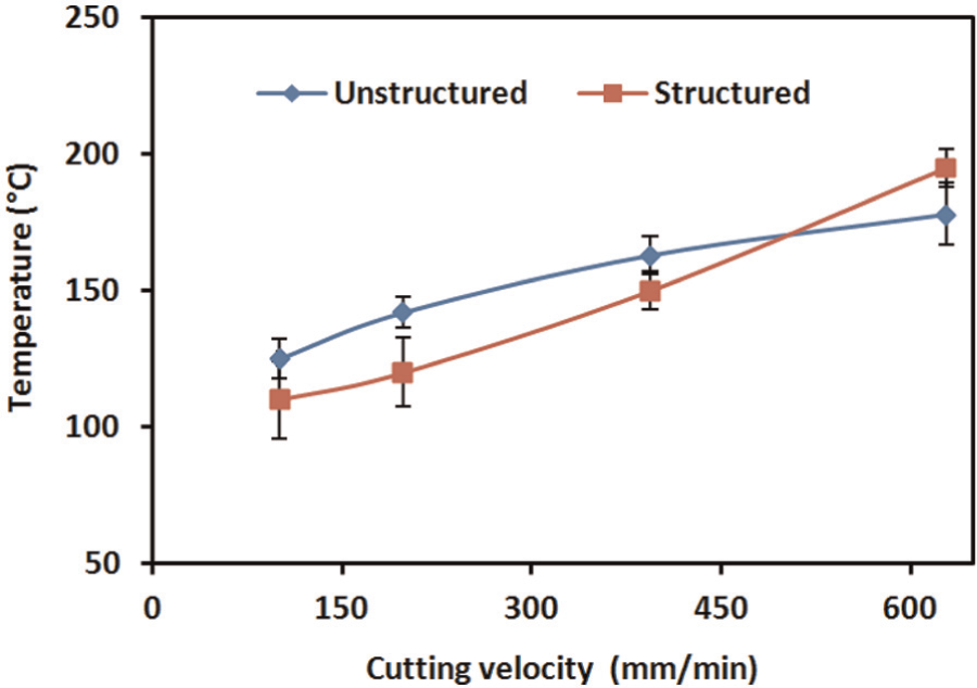
Variation in rake face temperature with cutting velocity when machining with lubricant.
Contact length
Figure 12 shows the average rake face tool–chip contact length plotted with respect to the cutting velocity. It can be seen from Figure 12 that the tool–chip contact length is significantly affected by the cutting speed and the flank face conditions. The contact length for the plain flank face follows the traditional trend with respect to the cutting velocity, while tool–chip contact length of the structured flank face was found to decrease significantly at lower cutting speeds.
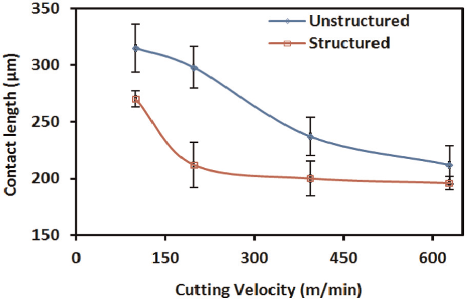
Variation in tool–chip rake face contact length with cutting velocity.
Variation of the contact length of the tool–workpiece clearance face with cutting speed is shown in Figure 13. It is evident from the plot that contact length on the clearance face follows an increasing trend with an increase in cutting speed. However, the average values of clearance face contact length for the structured cutting tool were decreased. This reduction in clearance face contact length is attributed to the effect of the structures forming a micro reservoir for a cutting fluid. Figure 14(a) and (b) shows SEM images of rake face contact length and clearance face contact length, respectively.
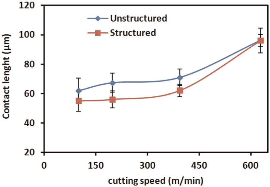
Variation in contact length of the tool–workpiece clearance face with cutting velocity.
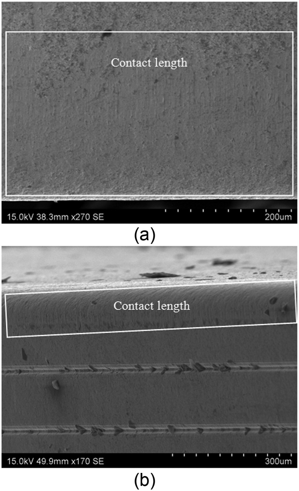
Contact length (a) on rake face of cutting tool and (b) on clearance face of cutting tool.
Flank land wear rate
Flank wear is a result of abrasion between the cutting edge (clearance side) and the machined surface and has been the standard by which the tool life is assessed. Flank wear has deterministic effects on workpiece’s surface finished, residual stresses and micro structure alterations. 26 For this study, the flank wear was examined on worn cutting tools by SEM. The variation of flank wear rate as a function of cutting speed is shown in Figure 15. An increase in a cutting speed tends to increase the temperature at cutting zone that substantially modifies the tool geometry. Typically, the rake angle becomes less negative, and hence the work material extruded below the tool. This results in an increased contact between the workpiece and the flank face of the cutting tool. For structured cutting tool, a decrease in the flank wear is evident from Figure 15 for the cutting speeds of 100,198 and 394 m/min. However, at the speed of 628 m/min, there is a rapid increase in the flank wear for the structured tool. As 628 m/min is a high cutting speed for AISI/SAE 4140, the increased flank wear at this speed can be attributed to the higher temperatures in a very narrow zone near the cutting edge.
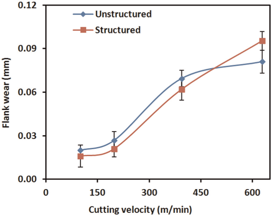
Flank wear with cutting velocity.
Sticking and sliding contact area
Energy-dispersive X-ray analysis (EDXA) was performed on the worn inserts to quantify the iron (Fe) transfer on the tool rake face along the contact length. Figures 16 and 17 show the corresponding contact length and the iron concentration for cutting speeds of 198 and 394 m/min for the rake and the flank face of the cutting tools, respectively.
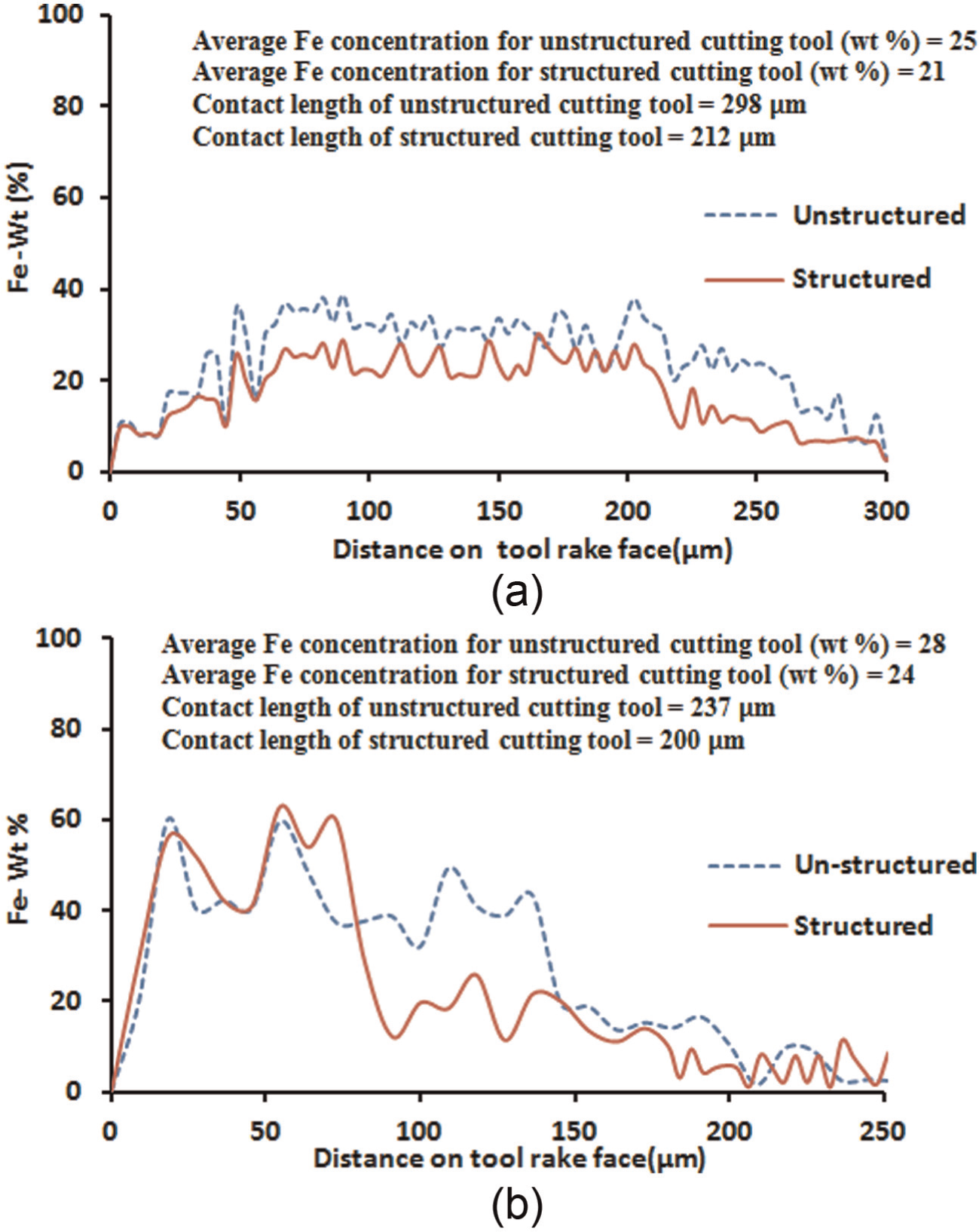
SEM–EDXA iron density maps along the tool rake face for cutting velocity of (a) 198 and (b) 394 m/min.
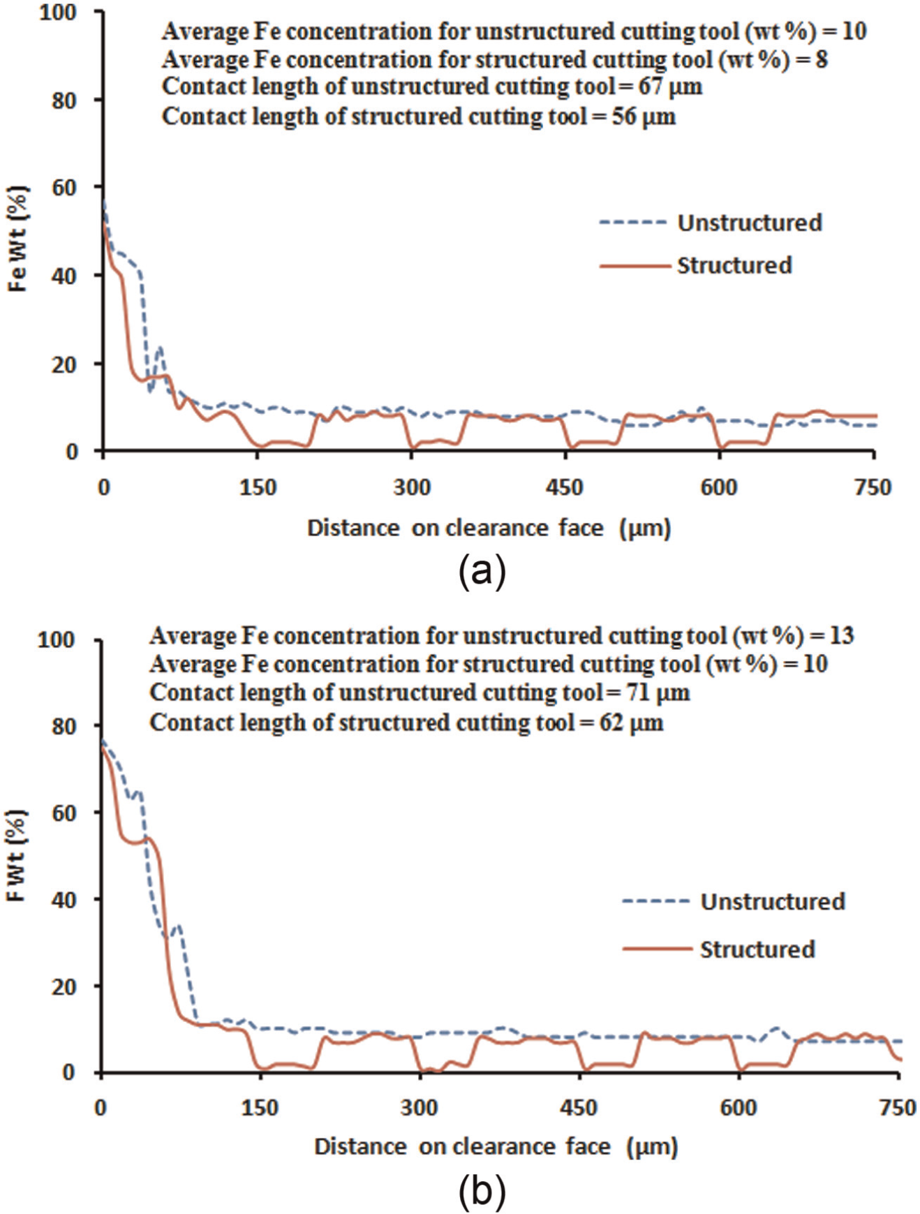
SEM–EDXA iron density maps along the tool clearance face for cutting velocity of (a) 198 and (b) 394 m/min.
On the rake face, for a cutting speed of 198 m/min, the unstructured flank face cutting tool shows no significantly increased weight percentage of iron transferred to the tool rake face. The overall average iron concentration was 25%. Thus, the sliding contact exists over an entire contact length. In contrast, the structured flank face cutting tool shows an average iron concentration decrease to 21%. However, at a cutting speed of 394 m/min, for the unstructured flank face cutting tool, the high concentration of iron transfer can be seen for almost 50% of total contact length concentrated till 145 μm from the cutting edge. This Fe transfer supports the presences of sticking and sliding contact conditions on the rake face with 50% due to sticking near the cutting edge, while the remaining 50% is sliding. The average iron weight percent transfer for the unstructured flank face cutting tool is 28%. For the structured flank face cutting tool, the average iron transfer reduces to 24% and was concentrated only at 42% of total contact length. This result indicates that flank face structures have not only reduced iron transfer but has also reduced the sticking zone on the rake face of the cutting tool. While on the clearance face, at lower speed of 198 m/min, the unstructured cutting tool shows average iron transfer of 10%, which reduces to 8% for structured cutting tool. For the cutting speed of 394 m/min, the average iron transfer was 13% for unstructured cutting tool which reduces to 10% for structured cutting tool. From these results, first, flank face structuring is shown to have a significant effect on improving the rake and flank face conditions. Second, it is evident that structures on the flank face only made contact with the workpiece in the vicinity of the cutting edge. Therefore, the structures on the flank face provide cutting fluid reservoirs rather than a micro debris trap.
Tool life and surface finish
In this study, flank wear measurements were made according to the standard ISO 3685:1993. 27 Figure 18 shows a variation of average flank wear as a function of cutting time for the cutting velocity of 283 m/min, feed of 0.1 mm/rev and depth of cut of 0.1 mm. Cutting tests were performed on computer numerical control (CNC) turning centre (machine tool name (MHP) lathe; MHP MT-50 (MDSI open CNC®)). The observed flank wear for both cutting inserts was regular and increased with the cutting time. However, the rate of wear on the flank for the structured cutting tool was found to be slower than that of the unstructured cutting tool. Moreover, the pattern was consistent with classical machining flank wear evolution. An extension of tool life by 18% was observed for flank face structured cutting tools.
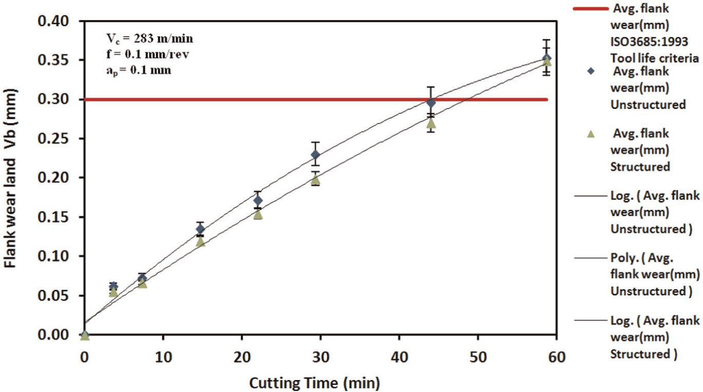
Growth of flank wear for structured and unstructured cutting tools.
It is established that tool wear rate depends on cutting temperature, contact stresses and the sliding velocity of the chip. 28 Flank wear first occurs due to abrasion, and as the wear progresses and temperature increases, diffusion also occurs. 29 Figure 18 indicates that the rate of flank wear at the start of cutting was basically the same for both tools. However, after a few minutes of cutting, the wear rate for the structured tool progressed slower than CT. The use of structures on the flank face strongly resisted flank wear in the followings ways: first, due to the use of lubricant and the structure itself. Structures not only decreased the area of contact for reduced local heat transfer, decreasing the effect of temperature on tool degradation, but also provided the site for lubricant and hence improved friction between the tool and workpiece. Second, the decreased contact length contributed to the decreased cutting forces, due to the reduced workpiece strength. The decrease in cutting forces reduces the amount of contact stresses at tool tip thus promoting tool life.
Ra values of surface roughness were recorded by Taylor Hobson Surtronic 25 roughness instrument. Cut-off length of 2.50 mm and evaluation length of 12.5 mm was used. The plot of Ra values of surface roughness as a function of cutting time is shown in Figure 19. It can be observed that the surface roughness for the flank face structured cutting tool is reduced. This can be attributed to reduced tool wear as surface is mainly a result of tool geometry and cutting conditions. 30
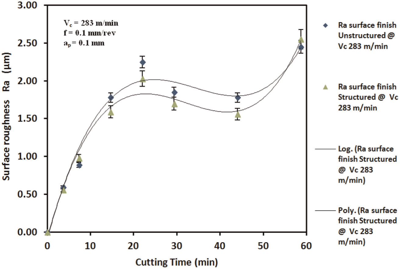
Surface roughness (Ra) versus cutting time.
When a cutting process is started and the tool starts to wear, the cutting edge corner becomes flattened, that is, the nose radius substantially increases. This is reflected in the decreased roughness. However, increased cutting forces and temperature due to the excessive flank wear progression make the machining process un-stabilised and the roughness increases. 31 The structured cutting tool reduced the temperature and the cutting forces, thus delaying tool wear and improving the surface finish.
Power demand
Environmental performance of a manufacturing system can be significantly improved by reducing energy consumption of a particular manufacturing process. And saving energy obviously has the potential to reduce global warming. For a machining process, this can be achieved by minimising power consumption and increasing the tool life. In this research, electricity consumption was recorded with the Fluke 345 Power Quality Clamp Meter. The Meter was clamped on the current supply cable of the three-phase wire for measuring current. The machining power was then calculated. Figure 20 shows the power consumption trend for a period of machining. Power can be separated into basic power (required by the machine) and tip power (for actual cutting).
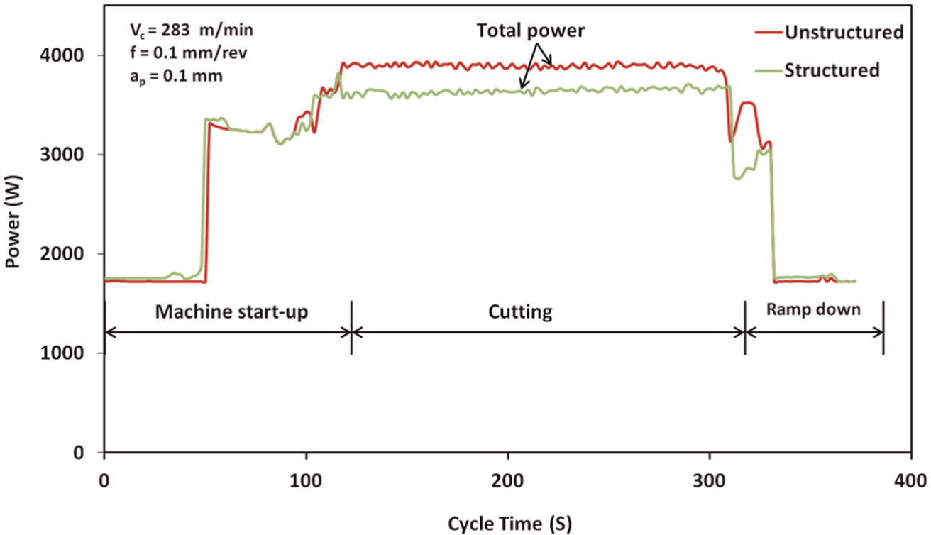
Power consumption profile of machining.
Figure 21 represents the tip power consumed while machining with an unstructured and a structured cutting tools. It can be noted from Figure 21 that the cutting power on the tip for the structured cutting tool was lesser than unstructured cutting tool. It was reduced by 37% on average. This reduction in cutting power is attributed due to the reduction in cutting forces.
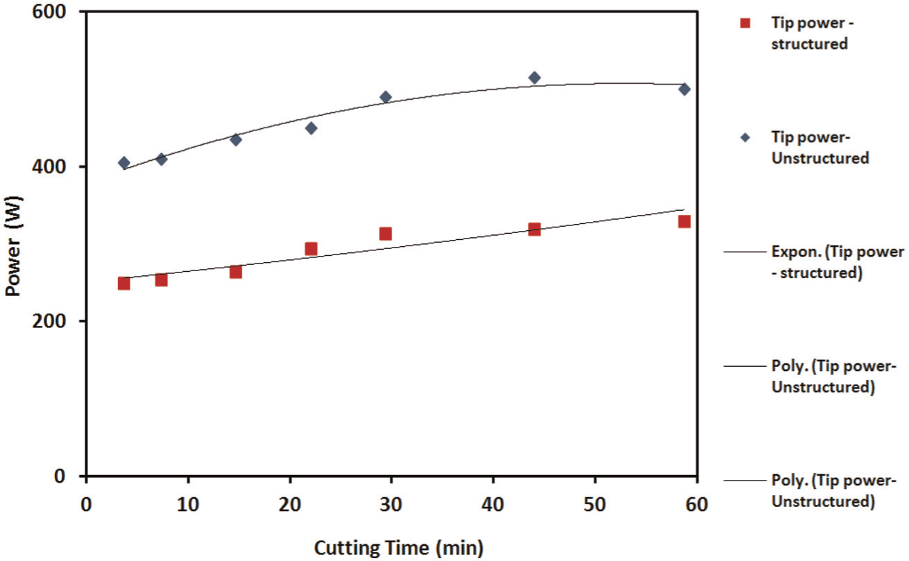
Cutting power demand for machining with unstructured and structured cutting tools at Vc = 283 m/min, f = 0.1 mm/rev and ap = 0.1 mm.
Conclusion
This research presents a study on surface structuring of the flank face of cutting tools to improve cutting performance in machining of AISI/SAE4140. The performance of the structured tools was compared to unstructured tools. The main conclusions of the study were as follows.
Flank face structuring reduced the rake and the flank face contact length. On average, iron weight percentage transfer was reduced by 15% on rake face and 22% on flank face. Flank face structuring of cutting tool also brought a 16% reduction in the sticking contact phenomenon.
Surface structuring on the flank face of the cutting tool led to a reduction in both cutting and feed forces. This reduction was 12% on average compared to using the unstructured tool. Furthermore, a decrease in tool temperature of 12% was observed at lower speeds. There is also an improvement found in the compression ratio and shear angle.
The tool life was increased by 18%, from 44 to 52 min with the flank face structured tool. Reduced flank wear growth rate contributed to improved surface finish of workpiece.
Flank face structuring enabled a significant 37% reduction on tip power (cutting power), improving energy footprints.
Footnotes
Declaration of Conflicting Interests
The author(s) declared no potential conflicts of interest with respect to the research, authorship, and/or publication of this article.
Funding
The author(s) received no financial support for the research, authorship, and/or publication of this article.