
Abstract
The article presents the results of experimental investigations to determine the effect of active surface morphology of grinding wheels with a zone-diversified structure on the form and size of chips generated during traverse internal cylindrical grinding of 100Cr6 steel. In the grinding process involving grinding wheels with a zone-diversified structure, chip formation phenomena differ in the rough and finish grinding zones of the tool. In order to expand one’s knowledge of this phenomena, the microtopography measurements of the grinding wheel active surface in the rough and finish grinding zones were made, as well as scanning electron microscopic observations of these areas after the dressing cut and following internal cylindrical traverse grinding. The conducted studies showed that chips in the rough grinding zone of the grinding wheel active surface are usually several hundred micrometers in length. In the finish grinding zone, however, mainly micro-chips were generated whose length does not exceed 100 µm (usually around 10 µm in length). In the rough grinding zone, shearing-type and flowing-type chips dominate with a few examples of spherical melted chips. Moreover, in the finish grinding zone, mainly slice-type and knife-type micro-chips were observed.
Keywords
Introduction
Increasing one’s knowledge of the basic phenomena in the cutting and abrasive machining processes is done on the basis of analyses of output parameters recorded during the execution of the processes under investigation or after its completion, such as force, power, temperature, acoustic emission, vibration, and parameters defining the quality of the workpiece surface. A particular and very interesting source of information regarding the conditions of the machining process is the analysis of the morphology of chips resulting from the process. Such analyses are especially useful in the case of grinding processes, where tools with a non-defined number and geometry of cutting blades are used. An analysis of bibliographic sources shows that information obtained on the basis of observations of chips generated during grinding processes are particularly important in the following areas of research:
Seeking a relationship between the form of chips and the process parameters;1–5
Investigation of basic phenomena during the grinding of new, hard-to-cut or untypical materials;6–10
Experimental verification of the theoretical analyses associated with the formation of the chip and its parameters such as undeformed chip thickness, relative chip volume, chip energy, and chip temperature;11–17
Better understanding of new varieties of the abrasive processes or determining the effect of the process’ modernization on its course.18–21
Analysis of traverse internal cylindrical grinding may be included in the last of the above-mentioned research areas. Traverse grinding processes are one of the most important recent trends in abrasive machining. Their essence lies in removing the whole machining allowance in a single pass of the grinding wheel while preserving the desired quality of the workpiece surface. 22 For internal cylindrical traverse grinding, special grinding wheels with zone-diversified structure were developed, 23 characterized by both the use of a conic chamfer and a different construction of the particular functional areas of the tool (Figure 1).
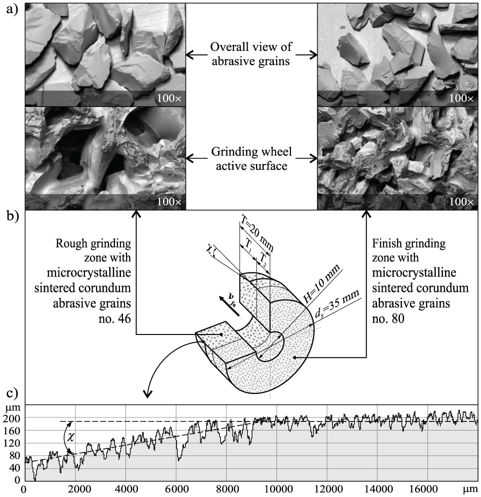
Zone-diversified structure grinding wheel for single-pass internal cylindrical grinding: (a) SEM micrographs of single abrasive grains and the GWAS, (b) construction scheme, and (c) micro-geometrical axial profile of the GWAS with an exposed conical chamfer angle χ (ds : grinding wheel outer diameter; H: grinding wheel inner diameter; T: grinding wheel total height in the axial direction; T 1: height of rough grinding zone; T 2: height of finish grinding zone; χ: angle of the grinding wheel conic chamfer).
Zone-diversified structure grinding wheels are characterized by a rough grinding zone constructed of relatively large-sized grains. The job of the rough grinding zone is removing the allowance, while the job of the finish grinding zone is sparking out and smoothing the surface. In such processes, the machining allowance is approximately 0.1–0.2 mm thick and in order to acquire its efficient removal in a single working pass, a conic chamfer needs to be formed while dressing the grinding wheel active surface (GWAS). The conic chamfer angle χ is dependent on a number of parameters, such as the grinding wheel coasting, the amount of the removed allowance, the grinding wheel height, as well as the requirements concerning surface quality. Indeed, the latter determines the width of the finish grinding and sparking-out zones. Modified macro-geometry of the GWAS allows for the total grinding allowance to be evenly distributed along a substantial length of the grinding wheel, and consequently, a higher number of active grains, removing the allowance takes part in the rough grinding process.
Such a unique design of zone-diversified structure grinding wheels affects their GWAS morphology. Consequently, the chip formation phenomena differ in both subsequent zones of the GWAS (rough and finish grinding zones). In order to expand our knowledge of these phenomena, the article describes results of analysis of the effect of GWAS morphology on the form of chips in traverse internal cylindrical grinding of 100Cr6 steel.
Methodology of experimental tests
Experimental position
The tests were carried out using an experimental position built on the basis of a universal grinding machine, namely, an RUP 28P by Mechanical Works Tarnow SA (Poland). A general view of the experimental position is presented in Figure 2.
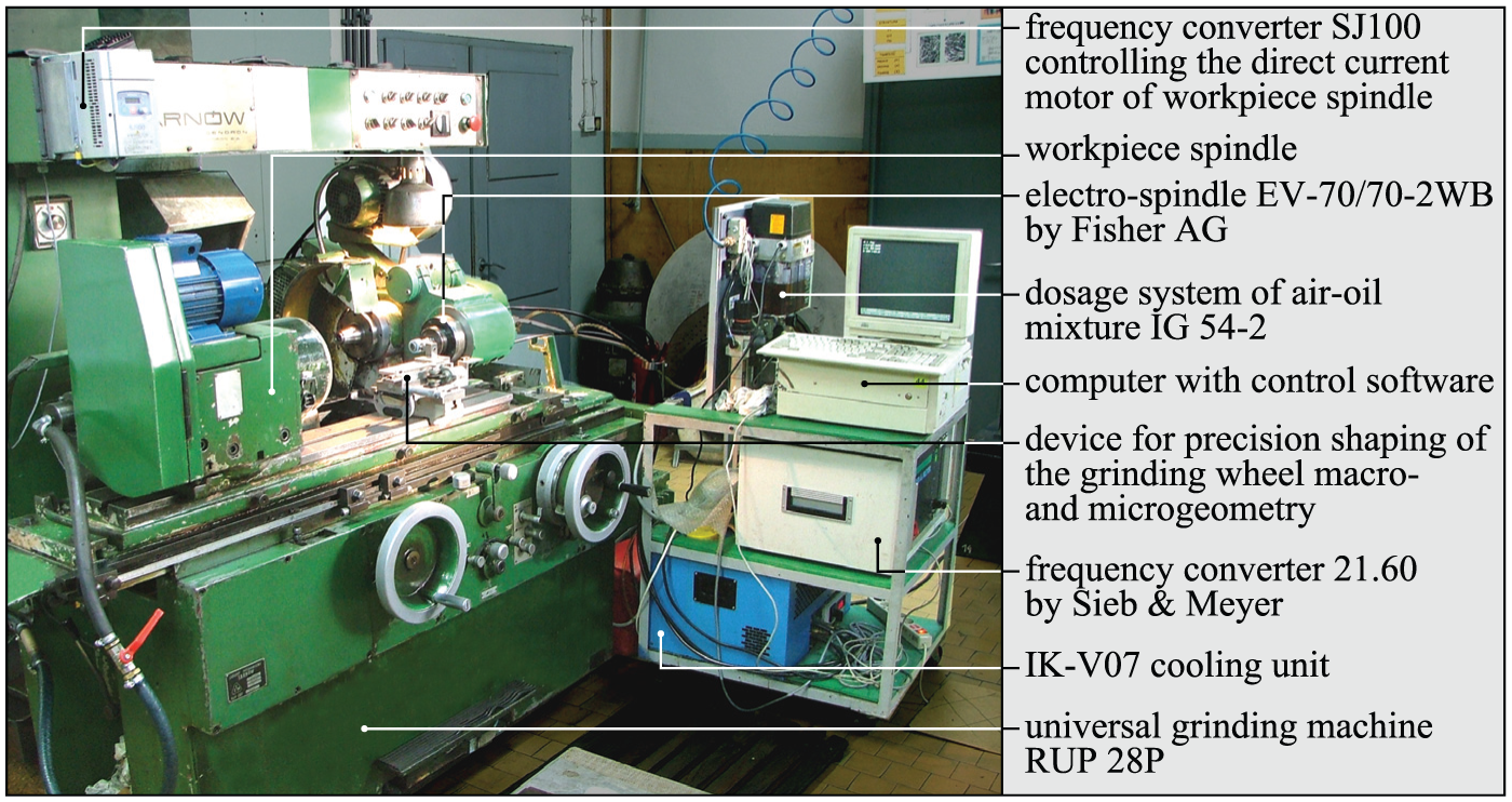
General view of experimental position based upon RUP 28P grinding machine by Mechanical Works Tarnow SA (Poland).
The position was equipped with the following devices:
An electro-spindle, type EV-70/70-2WB produced by Fischer AG (Switzerland) with maximum rotational speed nmax = 60,000 r min−1 and power P = 5.2 kW;
A dosage system of air–oil mixture, namely, IG 54-2 within the programmable logic controller, used for controlling the feeding cycles of oil and compressed air to the electro-spindle;
A cooling unit with an automatic liquid coolant temperature regulation system, namely, IK-V07;
A frequency converter, type 21.60 produced by SIEB & MEYER AG (Germany), used for supply and control of the electro-spindle;
A computer coupled with a converter using a serial connector, namely, RS232, equipped with Term51 software, used for the control of the spindle rotational speed and the monitoring of its working conditions (electrical grinding power);
A frequency inverter, namely, SJ100, which allows for frequency controlling of the workpiece spindle rotations;
A device for precision shaping of the grinding wheel macro- and microgeometry. 24
Grinding wheel
A grinding wheel of type 1 used in the experimental tests was made from microcrystalline sintered corundum SG™ (by Norton, USA) number 46 (in rough grinding zone) and 80 (in finish grinding zone). A vitrified bond with glass-crystalline structure25,26,27 was also used to fabricate the tool. Table 1 presents a detailed description of the grinding wheel used.
Description of grinding wheel with zone-diversified structure used in experimental tests.
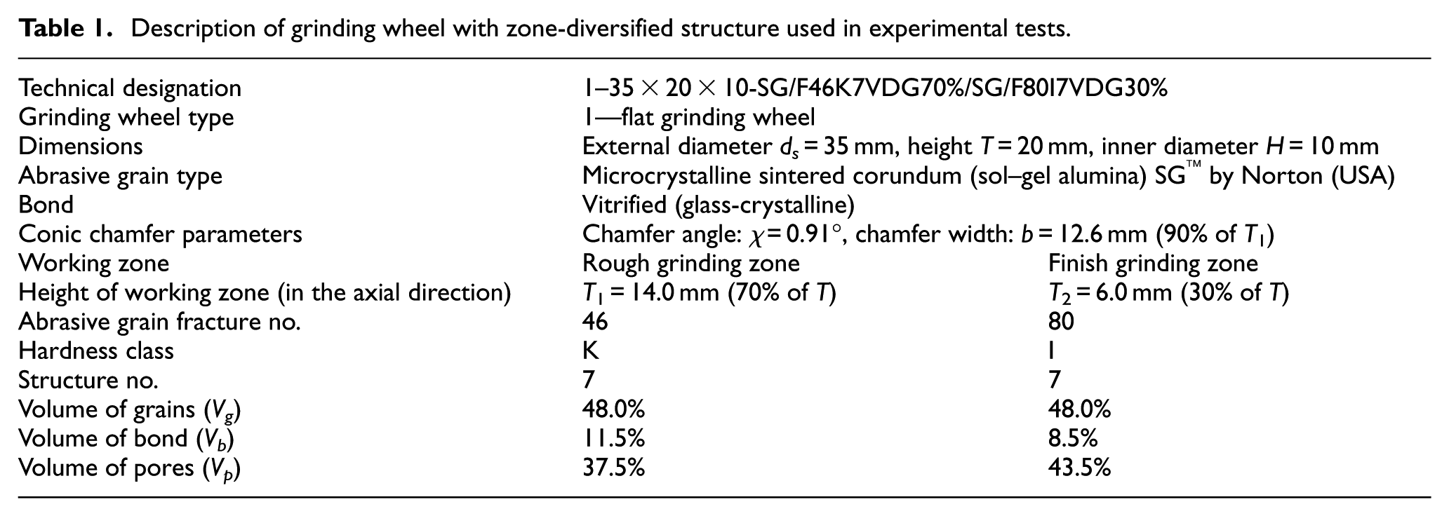
A conic chamfer with a width of b = 12.6 mm and an angle of χ = 0.91° was shaped upon the grinding wheels’ active surfaces. Chamfer parameters were adjusted to the amount of the machining allowance removed in a single pass (ae = 0.20 mm) and the height of the rough grinding zone (T 1 = 14 mm). In order to make quick and precise shaping of the conic chamfer with as specific GWAS geometric parameters possible, it was necessary to employ a special automated tool for dressing. 24 The precision required for shaping the conic chamfer using the developed device fell within the range of χ = 0°–1.5° is approximately ±3%.
Workpiece
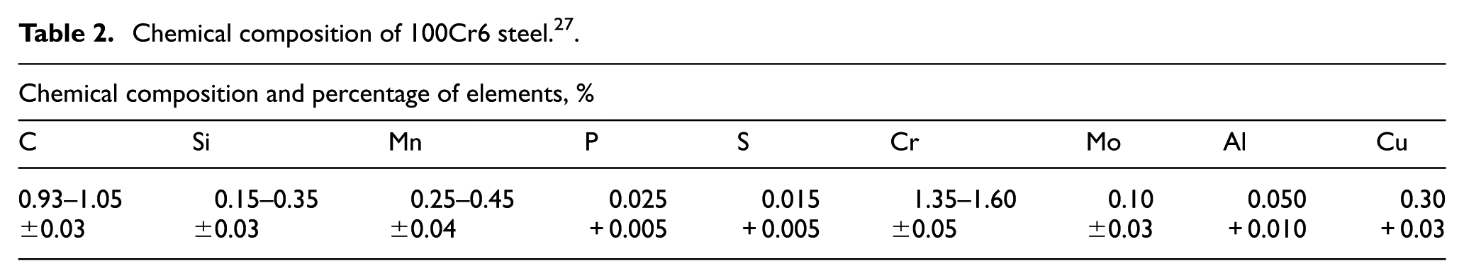
The tests were carried out using a semi-fabricated bearing rings made of 100Cr6 steel (62 ± 2 HRC) whose chemical composition is given in Table 2.
Chemical composition of 100Cr6 steel. 27
Grinding conditions
In the experimental tests, changes in the grinding power P and machined surface roughness (described by Ra parameter: arithmetic mean deviation of the workpiece roughness profile given in µm) were recorded during the removal of 4640 mm3 of the workpiece material. This corresponded to the grinding of 10 subsequent openings with their parameters shown in Table 3. The grinding wheel was dressed prior to machining the first workpiece.
Conditions of grinding process.
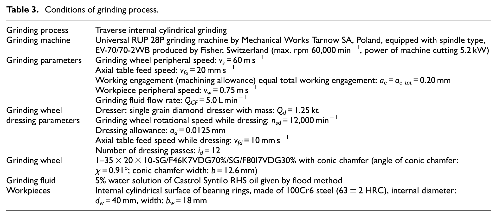
Before the beginning of the experiments (after dressing), the microtopography of individual work zones of the grinding wheel was measured and scanning electron micrographs were acquired. After the test, microtopography measurements of the GWAS were repeated while, additionally, axial profiles of the wheel were measured. The most important part of analysis, after grinding, was detailed microscopic observations of the GWAS using scanning electron microscopy (SEM). These allowed the registration of chips remaining in the intergranular spaces of the GWAS, both in the rough grinding and finish grinding zones.
Morphology measurement of the GWAS
Morphology, as a study of the shapes and forms of elements that create the GWAS, was determined in these investigations by microtopography and the axial profiles of the GWAS.
Microtopography measurements were carried out using a 3D optical profiling system, namely, a Talysurf CLI 2000 produced by Taylor Hobson Ltd (Great Britain)28,29 equipped with an LK-031 optical displacement sensor produced by Keyence (Japan), 30 presented in Figure 3(a). The laser triangulation-based sensor was connected to an LK-2001 controller (by the same producer) and allowed one to achieve a measurement resolution of 1 µm. The source of light used in the LK-031 sensor was a small semiconductor laser (wavelength: λ = 670 nm (visible red), power: Pl = 0.95 mW, spot diameter: approx. 30 µm).
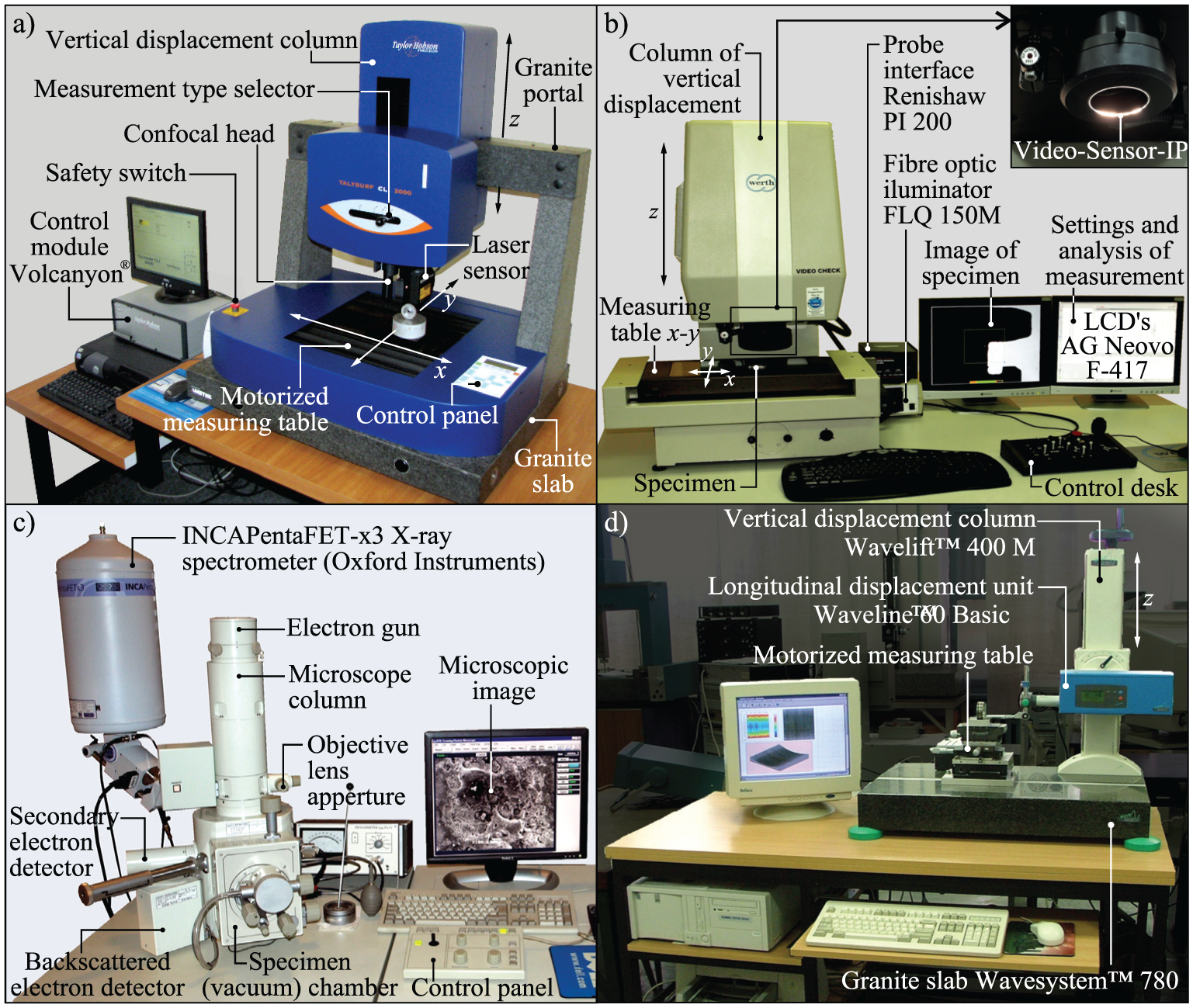
General views of measurement systems used in the experimental tests: (a) 3D optical profiling system Talysurf CLI 2000 by Taylor Hobson Ltd used for a non-contact measurement of the GWAS microtopographies; (b) bench-type multisensor coordinate measuring machine Video-Check®-IP 250 equipped with Video-Sensor-IP, produced by Werth Messtechnik GmbH used for registration of axial profiles of the GWAS; (c) scanning electron microscope JSM-5500LV by JEOL Ltd, used for assessment of the chips in the GWAS; and (d) stylus profilometer Hommel-Tester T8000 by Hommelwerke GmbH, used for measurements of workpiece surface.
Before measurements were begun, the grinding wheel was positioned in the working space of the CLI2000. After manual calibration of the LK-031 height relative to the measured GWAS (height set at 30 mm), the measurement conditions were set using Talysurf CLI 2000 2.6.1 software produced by Taylor Hobson Ltd. For each of the individual work zones of the GWAS, an area of the size of 2.5 mm × 2.5 mm was determined. Analysis and visualization of the measurement was carried out using TalyMap Silver 4.1.2 software, with Mountain Technology produced by Digital Surf (France).
For the measurements of the axial profiles of the grinding wheel, an advanced bench-type coordinate measuring machine (CMM) Video-Check®-IP 250 produced by Werth Messtechnik GmbH (Germany)24,31 was used and is presented in Figure 3(b). The CMM was characterized by a modular structure, which enabled it to adapt to specific applications. In the construction of the Video-Check®-IP 250, two main modules were used, namely: a measuring table moving on mechanical bearings with a magnetic mount and a vertical travel column with a vision head. The head was equipped with the Video sensor IP and was allowed to measure the basic geometrical parameters of the tested elements in incident and transmitted light at an optical zoom range from 50× to 150×. For a greater number of tested elements, the measurements could be carried out in automatic mode. The image of the measured elements was acquired by a high-resolution CCD camera and was then processed to detect the contours of these objects. All measurements during the experimental tests were carried out in automatic mode, utilizing a measuring program prepared with dedicated software, namely, WinWerth® 6.21 produced by Werth Messtechnik GmbH.
SEM observation of the chips
The products of the traverse internal cylindrical grinding process, that is, those in the form of various types of chips, were subjected to microscopic observation. In this case, a scanning electron microscope, namely, a JSM-5500LV by JEOL Ltd (Japan) was used.32,33 The instrument, presented in Figure 3(c), was equipped with two types of detectors—a secondary electron image (SEI) detector and a backscattered electron image (BEI) detector, the latter of which operated in high-vacuum mode (HVM) and low-vacuum mode (LVM). Using SEI, the resolution was 4.0 nm (Ua = 30 kV, WD = 6 mm) and magnifications from 18× to 300,000×, whereas using BEI the resolution was 5.0 nm (Ua = 30 kV, WD = 8 mm) at these same magnifications. During the experimental tests, a wide range of magnifications were used from 50× (general morphology of the chips) to 2000× (details of the structure of the chips) with a constant Ua = 20 kV. The acquired SEM micrographs were characterized by the following parameters: resolution 1280 × 960 pixels, 8-bit color depth, grayscale mode, and saving format *.bmp.
Workpiece surface roughness measurement
For the determination of the basic surface roughness parameters of the workpieces, a stylus profilometer, namely, a Hommel-Tester T8000 produced by Hommelwerke GmbH (Germany), 34 was used. The instrument, presented in Figure 3(d), was equipped with a TKL100 pick-up with a diamond stylus tip (tip radius r = 2.5 µm) working with a longitudinal displacement unit (traverse unit), namely, Waveline™ 60 Basic (tracing length l = 60 mm). This unit was mounted on a vertical displacement column, namely, Wavelift™ 400M (max. traverse lmax = 400 mm), placed on a granite plate, namely, Wavesystem™ 780.
The instrument used two types of software. For the measurement of the setting conditions, Turbo Roughness for Windows 3.1 was used, whereas for the visualizations of surface roughness profiles and calculation of basic parameters, HommelMap Basic 3.1.0, using Mountain Technology™ provided by Digital Surf, was used.
Results and discussion
The grinding process was preceded by an analysis of the state of the GWAS after the dressing cut. The results of the analysis are provided in Figure 4. The microtopography measurements of the grinding wheel surface in the rough (Figure 4(d)) and finish grinding zones (Figure 4(e)) were made, as well as SEM observations of these areas (Figure 4(b) and (c)). Microscopic observation showed that the GWAS was clean, without any contaminations, for example, in the form of chips, after previous grinding operations (the grinding wheel selected for the investigations had not been used before). A comparison of microtopography measurements of the GWAS and the roughness parameters designated from these measurements suggests that both the working zones of the wheel were prepared in a similar manner. They are characterized by approximated values of the parameters Sa, Sz, Sds, Sdq, and Sdr (Figure 4(d) and (e)). The biggest differences in values was shown by parameter Str (texture aspect ratio of the surface), as well as Sbi (bearing index). An approximately twice as low value of the Str parameter and, at the same time, an almost twice as high Sbi parameter for the surface of finish grinding zone reflects a more homogeneous character of this part of the grinding wheel, with the presence of a large number of aligned and sharpened vertices of microcrystalline sintered corundum abrasive grains No. 80.
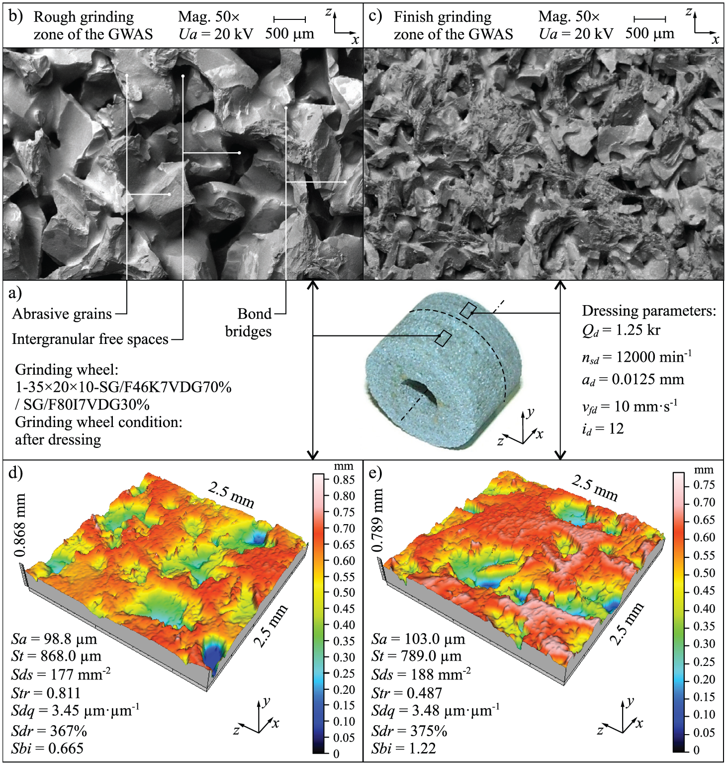
SEM micrographs (acquired using scanning electron microscope JSM-5500LV by JEOL Ltd) and microtopography with selected roughness parameters of individual work zones of grinding wheel after dressing (measured using 3D optical profiling system Talysurf CLI 2000 by Taylor Hobson Ltd): (a) macrophotography with overall view of grinding wheel, (b) SEM micrograph of rough grinding zone of GWAS—magnification 50×, (c) SEM micrograph of finish grinding zone of GWAS—magnification 50×, (d) microtopography of rough grinding zone of GWAS, and (e) microtopography of finish grinding zone of GWAS (Sa: arithmetic mean deviation of surface; Sbi: bearing index; Sdr: developed interfacial area ratio; Sds: density of summits of surface; Sdq: root-mean-square slope of surface; St: total height of surface; Str: texture aspect ratio of surface).
Figure 5 shows the results of experimental investigations, that is, changes in the values of the workpiece surface roughness parameter Ra (arithmetic mean deviation of the workpiece profile) and grinding power gain ΔP over material removal Vw. The recorded values of both parameters indicate gradual wear of the GWAS. Moreover, the gradual blunting of abrasive grains affects the increase in grinding power (Figure 5(b)). As abrasive grains of microcrystalline sintered corundum are characterized by their ability to self-sharpen, the quality of the ground surface remained at an acceptable level (Ra < 0.63 µm) throughout the range of test results obtained (Figure 5(a)).
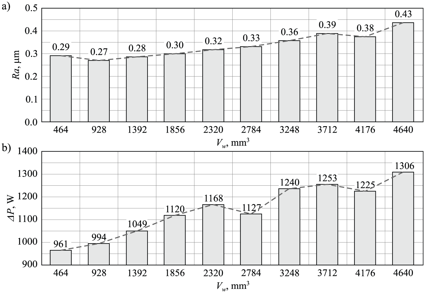
Changes in values of workpiece surface roughness parameter Ra and grinding power gain ΔP over material removal Vw : (a) arithmetic mean deviation of the workpiece profile Ra and (b) grinding power gain ΔP.
After completion of the grinding tests, the surface microtopography of individual functional zones of the grinding wheel was measured again (Figure 6(b) and (c)). Additionally, an axial profile of the grinding wheel (Figure 6(a)) was registered. Comparison of the designated roughness parameters of the GWAS after grinding (Figure 6(b) and (c)) with parameters appointed after dressing (Figure 4(d) and (e)) mainly indicates a significant reduction in the number of vertices (Sds parameter) in both functional zones of the grinding wheel. It should also be noted that there was an almost twofold reduction in the value of the arithmetic mean deviation of the surface roughness (Sa = 103 µm before and Sa = 54 µm after grinding) at a comparable total height of the wheel in the finish grinding zone (St = 742 µm before and St = 735 µm after grinding—Figures 4(e) and 6(c)). Such changes in surface roughness parameters of the wheel show quite significant smoothing cutting vertices of active abrasive grains which come into contact with the workpiece. Indications of wear on the abrasive grains were also clearly visible in the recorded SEM images (Figures 7–10).
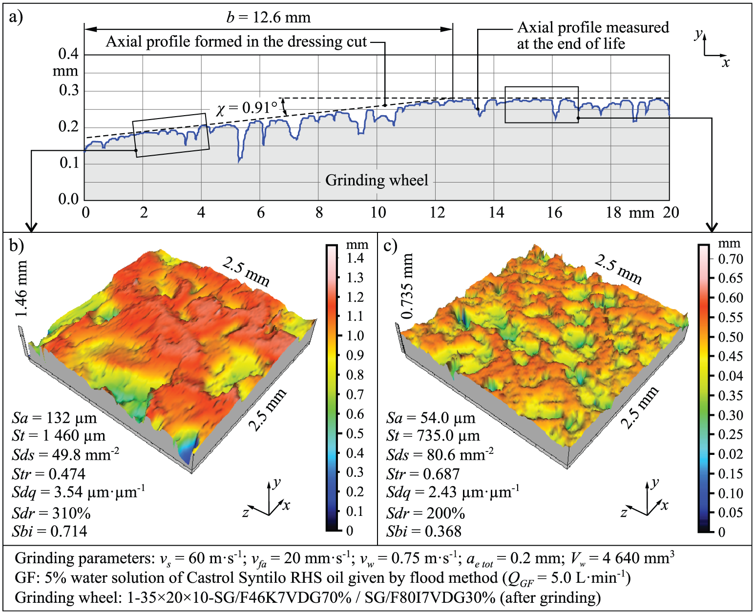
Axial profile of grinding wheel (measured using bench-type multisensor CMM Video-Check-IP 250 by Werth Messtechnik GmbH) and microtopography with selected roughness parameters of individual working zones of grinding wheel at the end of life (measured using 3D optical profiling system Talysurf CLI 2000 by Taylor Hobson Ltd): (a) axial profile of GWAS, (b) microtopography of rough grinding zone of GWAS, and (c) microtopography of finish grinding zone of GWAS (Sa: arithmetic mean deviation of the surface; Sbi: bearing index; Sdr: developed interfacial area ratio; Sds: density of summits of surface; Sdq: root-mean-square slope of surface; St: total height of surface; Str: texture aspect ratio of surface).
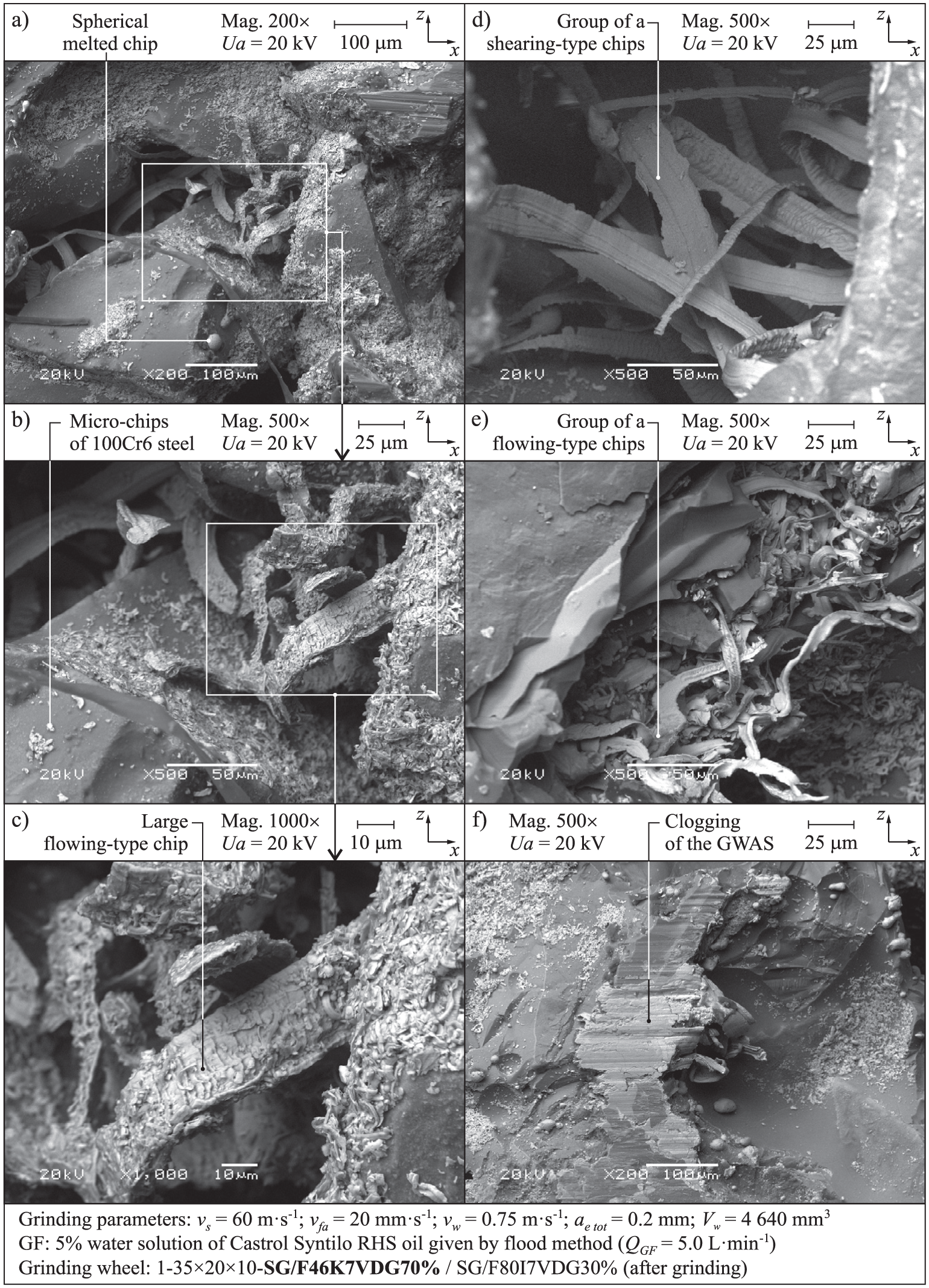
SEM micrographs of large chips observed in rough grinding zone of grinding wheel after machining: (a) magnification 200×, (b) magnification 500×, (c) magnification 1000×, and (d–f) magnification 500× (all micrographs acquired by scanning electron microscope JSM-5500LV by JEOL Ltd).
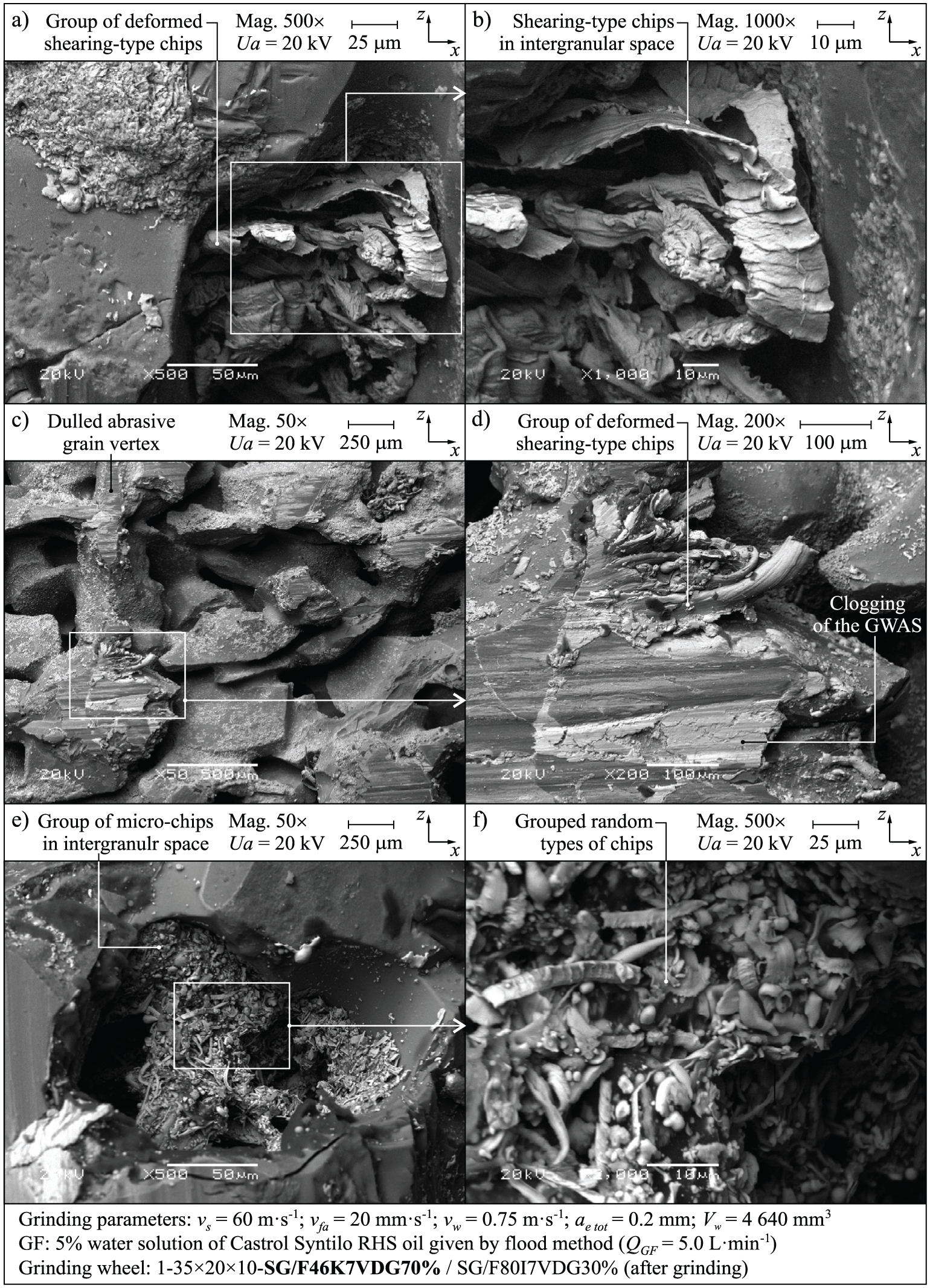
SEM micrographs of deformed chips observed in rough grinding zone of grinding wheel after machining: (a) magnification 200×, (b) magnification 500×, (c) magnification 50×, (d) magnification 200×, (e) magnification 50×, and (f) magnification 500× (all micrographs acquired by scanning electron microscope JSM-5500LV by JEOL Ltd).
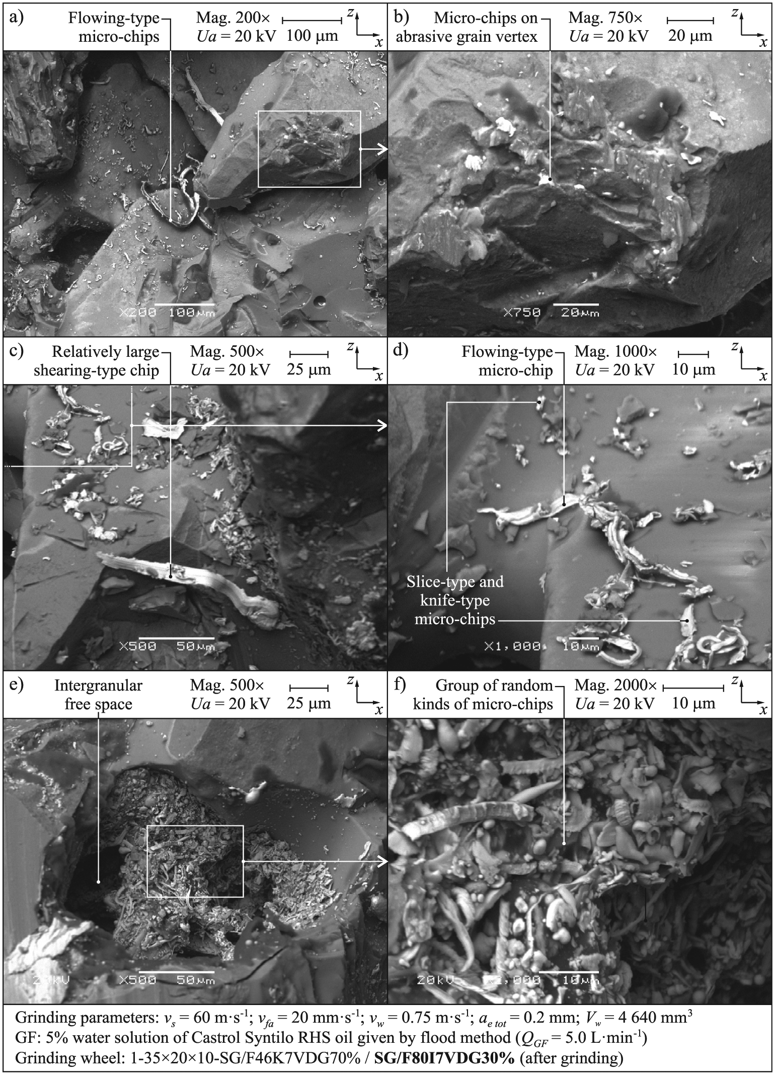
Overall SEM micrographs of micro-chips observed in finish grinding zone of grinding wheel after machining: (a) magnification 200×, (b) magnification 750×, (c) magnification 500×, (d) magnification 1000×, (e) magnification 500×, and (f) magnification 2000× (all micrographs acquired by scanning electron microscope JSM-5500LV by JEOL Ltd).
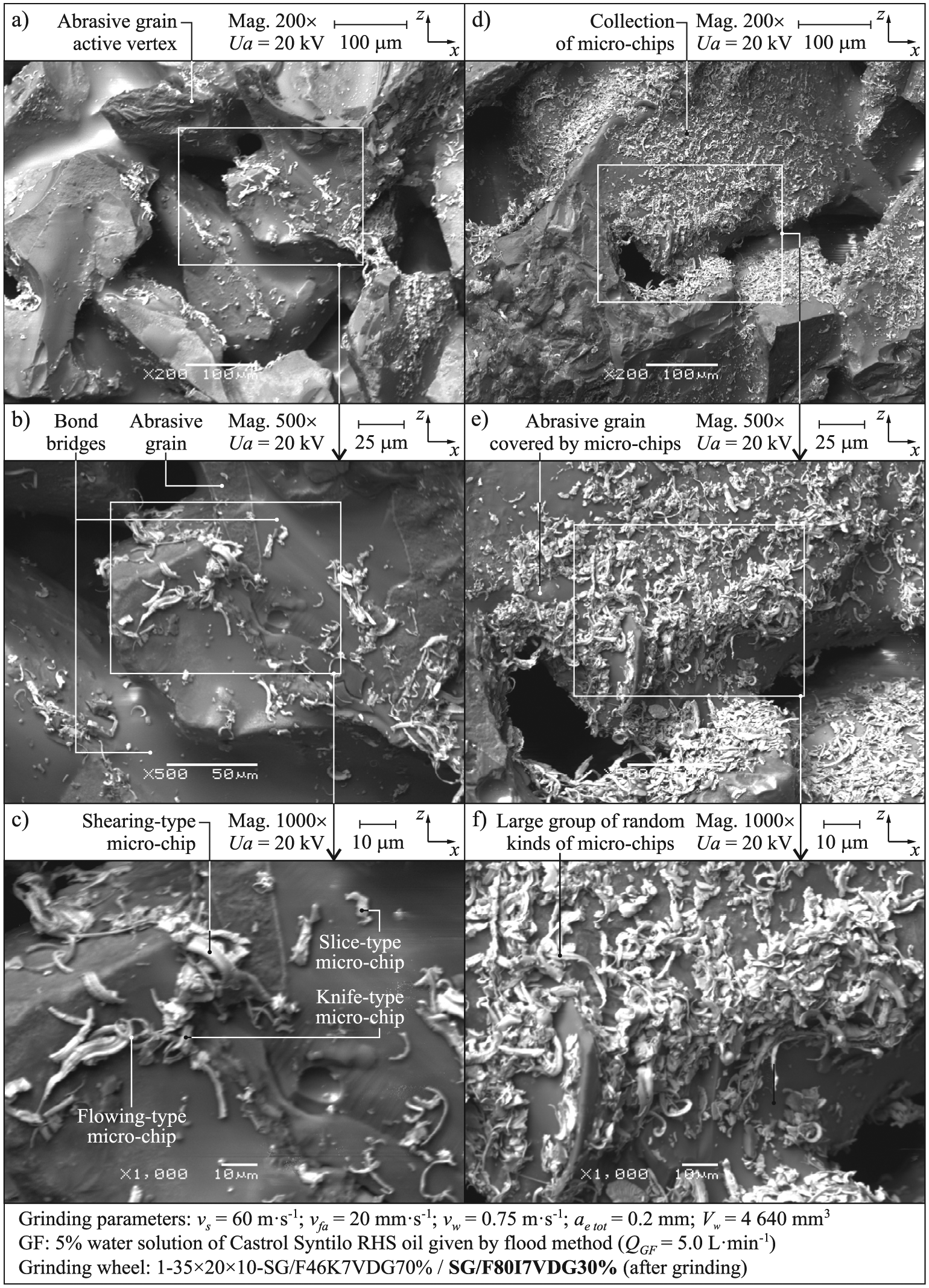
Detailed SEM micrographs of micro-chips morphology in finish grinding zone of GWAS after machining: (a) magnification 200×, (b) magnification 500×, (c) magnification 1000×, (d) magnification 200×, (e) magnification 500×, and (f) magnification 1000× (all micrographs acquired by scanning electron microscope JSM-5500LV by JEOL Ltd).
The grinding process was carried out with a relatively high material removal rate for the internal cylindrical grinding process, namely, Qw ≈24 mm3 s−1. As a result, a wide range of different types of chips could be observed on the GWAS, including spherical melted chips (Figures 7–10). A detailed analysis of the remaining chips on the GWAS was conducted separately for the rough (Figures 7 and 8) and finish grinding zones of the grinding wheel (Figures 9 and 10).
A comparison of chips recorded on these two groups of images discloses primarily a significant difference in the size of chips generated by the rough (Figures 7 and 8) and finish grinding zones of the GWAS (Figures 9 and 10). Chips in the large-grained conical zone of the GWAS are usually several hundred micrometers in length (Figures 7(a)–(e) and 8(a)–(d)). However, micro-chips can be seen in the fine-grained cylindrical zone, the length of which does not exceed 100 µm, and which in most cases oscillates around 10 µm in length (Figures 9(e) and (f) and 10(d)-(f)). This is mainly due to the differences in the morphology of both functional zones of the grinding wheel and the specific nature of traverse grinding. In the single-pass grinding process carried out using zone-diversified grinding wheels, the total machining allowance is spread out over a large area and is removed predominantly in the conical (large-grained) zone of the grinding wheel. However, in the cylindrical (fine-grained) zone of the grinding wheel, finish grinding and sparking out of the machined surface occur with substantially less machining allowance. The size of this allowance in the finish grinding zone depends on the material removal rate (total machining allowance and axial table feed speed of the grinder), the cutting ability in rough grinding zone of the GWAS, as well as on the stiffness of the grinder. Often during finish grinding, the grinder components (especially the grinding wheel and workpiece spindles) return to the nominal position, having been slightly deflected by large forces during rough grinding earlier.
Analysis of SEM micrographs also showed that among the plurality of types of chips defined in work, 6 shearing-type (Figures 7(d) and 8(a)–(d)) and flowing-type chips (Figure 7(a)–(c) and (e)) dominate in the rough grinding zone. Shearing-type chips are usually long and straight and occur when the cutting edges of grinding wheel are still sharp. The length of this type of chips decreases with an increase in the abrasive wear of the GWAS. Flowing-type chips are more slender and curly than shearing-type chips and are the result of the grinding process when the grinding wheel is still sharp and are usually generated with the greatest extent directly after the dressing cut. Difficult conditions in the grinding area also led to the formation of a few spherical melted chips (Figure 7(a)). Melted chips occur when a large amount of grinding heat is generated and conducted into the chips. In this grinding zone, some clogging on the abrasive grains’ active vertices was also observed (Figure 7(f)). These are formed from the sticking of chips to the GWAS and negatively affect the durability of the grinding wheel (heat spots on the GWAS), as well as the quality of the ground surface, thereby contributing to the creation of thermal defects.
Observations of micro-chips on the finish grinding zone of the GWAS (Figures 9 and 10) showed that in addition to the aforementioned types of chips, there are also slice-type and knife-type chips (Figures 9(d) and 10(a)–(f)). As in the case of conical rough grinding zone, the cylindrical area of the grinding wheel contained some micro-cloggings on the abrasive grains. Slice-type micro-chips are related to the presence of micro-clogging on the abrasive grain active vertices and they are the loading area that fall from the grinding wheel. Knife-type chips occur usually before slice-type chips when there are smaller clogging areas in the GWAS and can be found wherever slice-type chips occur. The presence of a larger number of varieties of micro-chips results, in addition, from a smaller machining allowance in this area of the GWAS. With a low value of cross-cutting per single active vertex of abrasive grain, the formation of long shearing-type and flowing-type micro-chips is much less likely to occur.
Referring to the results of the analyses obtained compared to data contained in the literature, it may be stated that in the analyzed traverse grinding process, all the known forms of chips described earlier for the typical and classified varieties of grinding 6 occur. It should be noted, however, that up to now morphological analyses of chips shaped by microcrystalline sintered corundum abrasive grains have not been conducted on such a scale. Referring the thus obtained results to the information given in the source literature, it may be concluded that in the case of microcrystalline sintered corundum abrasive grains, there is a great variation in the size of chips with respect to chips shaped by the abrasive grains of other types (white fused alumina 99A,3,14 SiC, 21 Diamond,8,11 or cBN5,13).
In the conducted research, both the presence of numerous micro-chips (about 10 mm in length) and chips with significant dimensions (under 1 mm in length) on the GWAS were recorded. This is, in part, due to the zonal diversified construction of the grinding wheel containing abrasive grains with different numbers (46 in the rough and 80 in the finish grinding zone) but mainly from the type of abrasive grains used with a microcrystalline structure. A self-sharpening process by chipping crystallites and the revealing of new sharp edges is characteristic for these grains. A large number of abrasive grains’ micro-vertices cause the total machining allowance to be divided into multiple micro-edges, thereby significantly reducing the volume of workpiece material per individual edge. In this context, the analyzed process is similar to grinding using other types of abrasive grains of a microcrystalline structure, such as microcrystalline cubic boron nitride.
However, in the rough grinding zone of the wheel, in which abrasive grains of larger sizes are located, the material removal process occurs intensively, leading to the generation of individual chips of large volume and dimensions. For these process conditions, chips are obtained which may be compared with those chips obtained in the process of efficiently grinding using abrasive grains of a mono- and polycrystalline structure (e.g. white fused alumina 99A, SiC, or monocrystalline cBN).
Conclusion
The wide range of analysis of the active surface morphology of grinding wheels with zone-diversified structure (before and after grinding) presented in the text allowed one to conduct reliable analyses of chips recorded on the GWAS after machining. The analysis covered both the size and types of chips in the rough and finish grinding zones of the grinding wheel on the basis of acquired comprehensive set of SEM micrographs. The most important conclusions that can be drawn from the research carried out include the following:
The varied morphology of individual functional zones of the zone-diversified structure of the grinding wheel significantly affected the form of chips and their size in traverse internal cylindrical grinding of 100Cr6 steel;
Chips in the rough grinding zone of the GWAS are usually several hundred micrometers in length, while micro-chips mainly generated in the finish grinding zone possessed a length not exceeding 100 µm (usually around 10 µm in length), which was the effect of zone diversification in GWAS morphology, as well as the specific nature of traverse grinding;
Shearing-type and flowing-type chips dominate in the rough grinding zone, with a few examples of spherical melted chips;
Although shearing-type and flowing-type micro-chips also appeared in the finish grinding zone, mainly slice-type and knife-type micro-chips were observed, which resulted mainly from smaller sizes of abrasive grains and a small machining allowance in this area of the GWAS.
Footnotes
Appendix 1
Acknowledgements
The authors would like to thank the employees of Koszalin University of Technology for their help and support in selected steps of the experimental investigations: Mrs Daniela Herman, DSc, PhD, from the Division of Fundamentals of Materials Science and Technical Ceramics of the Faculty of Technology and Education, for preparing the grinding wheels for tests; Mr Andrzej Nowicki from Laboratory Team I for his help during the experimental investigations of the grinding process; Mr Krzysztof Maciejewski from the Laboratory of Metrology And Measurement Systems for the stylus measurements of surface microtopographies of the workpieces; and Mr Ryszard Gritzman from the Central Laboratory of the Faculty of Technology and Education for acquisition of the SEM micrographs.
Declaration of conflicting interests
The author(s) declared no potential conflicts of interest with respect to the research, authorship, and/or publication of this article.
Funding
The author(s) received no financial support for the research, authorship and/or publication of this article.