
Abstract
This article presents the results of experimental tests aimed at determining the influence of shaping the microgeometry of particular functional zones (rough and finish grinding) of the grinding wheel active surface in the dressing cut and what effect this would have on the results of the internal cylindrical grinding process of steel 100Cr6. Single-pass grinding processes and the grinding wheel used in them are described. Grinding wheels with zone-diversified structure, made from abrasive grains along the basis of Al2O3 (white fused alumina 99A and microcrystalline sintered corundum), are characterized, and the construction of a special device for precise shaping of the conic chamfer on the grinding wheel active surface is presented. The experimental test results form the basis for determining the influence of the chief dressing parameters (grinding wheel peripheral speed vsd, dressing axial feed rate vfd) on the selected machined surface roughness parameters (Ra, Rz, RSm, Rdq), surface bearing ratio and grinding power P in the internal cylindrical traverse grinding process. It was proven that the most advantageous grinding results are obtained when using different dressing parameters for the conic rough grinding zone and the cylindrical finish grinding zone of the grinding wheel. When shaping the grinding wheel conic chamfer, increased values of the dressing feed rate vfd(cone) need to be used in order to reduce the grinding power. The most advantageous parameter values for describing the machined surface roughness were obtained with low values of axial table dressing feed rate vfd(cylinder), providing precise alignment and sharpening of the grinding wheel active surface cylindrical zone.
Keywords
Introduction
One of the most important factors determining the course of the grinding process is the condition of the grinding wheel active surface (GWAS). Both the macro- and microgeometry of the GWAS influence the number of active grains, the cross sections of the layers cut with a single grain and the volume of the intergranular free spaces. The characteristics of the GWAS are first of all determined by the tool construction, that is, the kind and size of the abrasive grains, the bond type and the structural openness. The GWAS condition can also be influenced by the proper selection of the dressing cut parameters.1,2 The macro- and microgeometry shaped in this manner allows the grinding wheel cutting abilities to be optimally used, as well as enabling adjustment of the GWAS to the given machining task, for example, different rough and finish grinding conditions.
It should be stressed, however, that the advantages resulting from shaping given macro- and microgeometry on the GWAS will only be obtained during the life of the tool. As the wear progresses, the GWAS returns to its nominal state resulting in, among other issues, the construction of the abrasive grains (mono-, poly- or microcrystalline) or the grain binding force of the bond. For this reason, modification of the dressing cut parameters is most advantageous when carried out during those processes in which the dressing cut is performed relatively frequently.
An example of such a process is the internal cylindrical traverse grinding performed by grinding wheels manufactured from cheap grains of white fused alumina 99A or microcrystalline sintered corundum SG®.
Internal cylindrical traverse grinding
In traverse grinding processes, the total machining allowance is removed in a single pass of the grinding wheel. Nadolny 3 shows that the most common traverse processes include external cylindrical continuous path–controlled grinding (CPCG), in which grinding wheels made from superhard abrasive grains are used.4–8 What has also been developed are traverse grinding methods using grinding wheels made from Al2O3 grains.9,10
In relation to internal cylindrical grinding processes, the subject literature offers descriptions of processes called Peelgrinding and Internal Deep Traverse Grinding, 11 as well as an example of cylindrical grinding in a single pass using the Quickpoint method. 12 This method consists of reducing the area of contact between the grinding wheel and the workpiece to the aforementioned point, hence the name of the method, by deviating the grinding wheel axis from the workpiece axis by an angle αk = 0.5°.13,14
What are used in Peelgrinding and Traverse Grinding processes are grinding wheels manufactured from cubic boron nitride (CBN) with total height T < 6 mm, characterized by a conic rough grinding zone. Such grinding wheels make it possible to remove a total machining allowance of approximately ae tot = 0.15 mm in a single pass. At the same time, the grinding power is decreased and so is the tendency to shape conic openings. Moreover, flexibility improves compared to traditional cylindrical grinding, while the high process reliability and high quality of the workpiece surface are maintained. 11
The conic chamfer angle χ is of crucial importance during the course of the rough grinding process. It makes it possible to evenly spread the total machining allowance (ae tot) over the length of the abrasive tool, thanks to which a greater number of active abrasive grains take part in the rough grinding process, removing the machining allowance corresponding to the effective value of the working engagement (ae eff) (Figure 1).
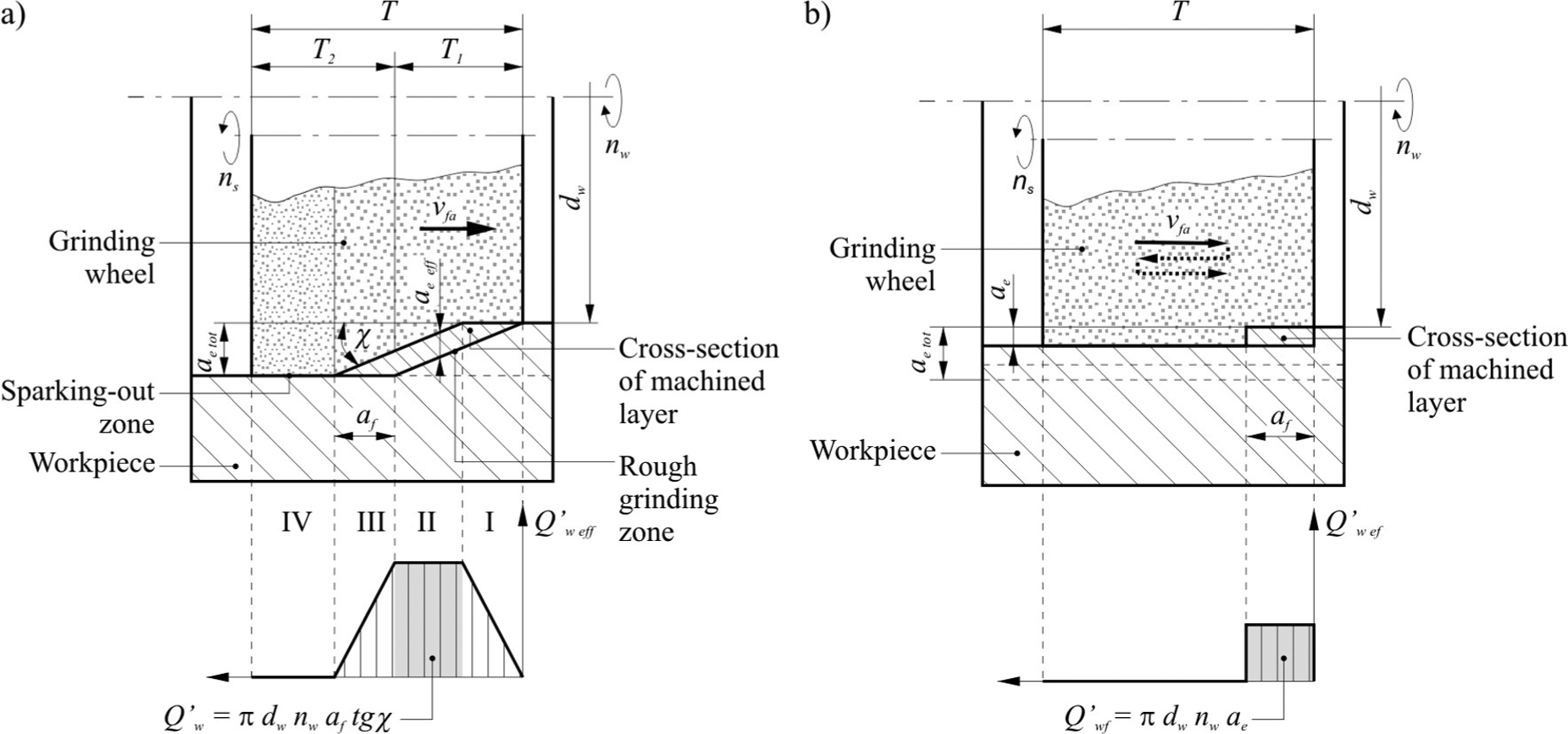
Comparison of wheel load in the implementation of internal cylindrical traverse grinding using (a) grinding wheel with conic chamfer and (b) conventional reciprocal (multi-pass) grinding.
The χ angle value depends on a number of parameters such as the grinding wheel coasting, the volume of the removed machining allowance, the grinding wheel height and the requirements concerning the surface quality. The last of these parameters listed determines the width of the rough and sparking-out zones. As a result of grinding wheel wear, the rough grinding zone moves into the finish grinding and sparking-out areas, which leads to its shortening.
In such grinding processes, variable grinding wheel loads can occur within four basic zones (Figure 1). In Zone I, there is an increase in the grinding wheel load up to its constant value in Zone II. The load value in Zone II may be calculated through proper material removal rate determined in the following way
where dw is the workpiece internal diameter, nw is the workpiece rotational frequency, af is the axial feed (feed engagement) and χ is the conic chamfer angle.
A drop in the load occurs in Zone III that is analogous to its increase in Zone I, with the difference being that, as well as removing the machining allowance it also enables finish grinding to take place. In Zone IV, there is both finish grinding and sparking out, resulting in elastic deformations occurring between the workpiece and the grinding wheel spindle.
Application of increased grinding wheel peripheral speed vs = 60–80 m/s and properly shaped GWAS macrogeometry, divided into the conic zone with angle χ = 5° and 2–4 mm-long cylindrical finish grinding zone, allows for obtaining machining allowance at the level of Qw = 24.0–37.7 mm3/s. A long-enough sparking-out zone guarantees the acquisition of a machined surface roughness of approximately Rz < 1 μm. 11
The described grinding wheel geometry allows for increased machining allowance by raising the axial table feed speed vfa. Even though this leads to an increase in the rough grinding zone load, it is still possible to obtain a good-quality surface thanks to the manifold grinding of the workpiece by the cylindrical finish grinding zone. As a result, with a machining efficiency comparable to hard turning, a far better surface quality is obtained. 11
Due to previous works on increasing the effectiveness of single-pass CPCG, Klocke et al. 15 developed a grinding wheel made of two zones that differed in CBN grain size. Such a grinding wheel is characterized by a total height in the axial direction T = 5 mm and was divided into a conic rough grinding zone made from B 91 grains, constituting approximately 50% T (χ = 15°), a cylindrical zone with the same grain (about 10% T) and a finish grinding zone made from B 151 grains (approximately 40% T).
Due to the fact that thus far only expensive grinding wheels, made from CBN grains that required specialist grinders with considerable stiffness and high grinding speeds (vs > 60 m/s), have been used in single-pass processes, the need to develop new constructions of grinding wheels from far cheaper grains, based on Al2O3, was born.
Grinding wheels with zone-diversified structure
Nadolny et al. 16 developed the structure and production method of grinding wheels with zone-diversified structure, characterized by the varied structure of the conic rough grinding and cylindrical finish grinding zones, made from microcrystalline sintered corundum grains and a glass-crystalline ceramic bond from the CaO–MgO–Al2O3–SiO2 system (see more on glass-ceramic bond in Herman and colleagues17–19).
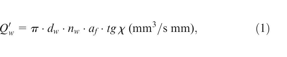
Such grinding wheels are characterized by their rough grinding zone which is made of relatively large-sized grains, while the cylindrical finish grinding zone has smaller grains. The goal of the rough grinding zone is to remove the machining allowance, while that of the finish grinding zone is to spark out and smooth the surface. For this reason, a more open structure is introduced into the rough grinding zone so as to facilitate the deposition of the machined material chips and grinding wheel wear products created. The grinding wheel structure in the finish grinding zone is compact, due to the far lower microcrystalline sintered corundum grain cutting capacity, compared with CBN grains, and the grinding wheel height was increased to T = 20 mm.Figure 2 presents a construction diagram, microscopic views of the functional zones and the axial profile of the microgeometry of the GWAS with zone-diversified structure, designed for traverse cylindrical grinding.
Zone-diversified structure of grinding wheel for traverse internal cylindrical grinding: (a) SEM images of single abrasive grains and grinding wheel active surface; (b) construction scheme; and (c) microgeometrical axial profile of the grinding wheel active surface with an exposed conical chamfer angle χ.
Device for precision shaping of the macrogeometry of the GWAS
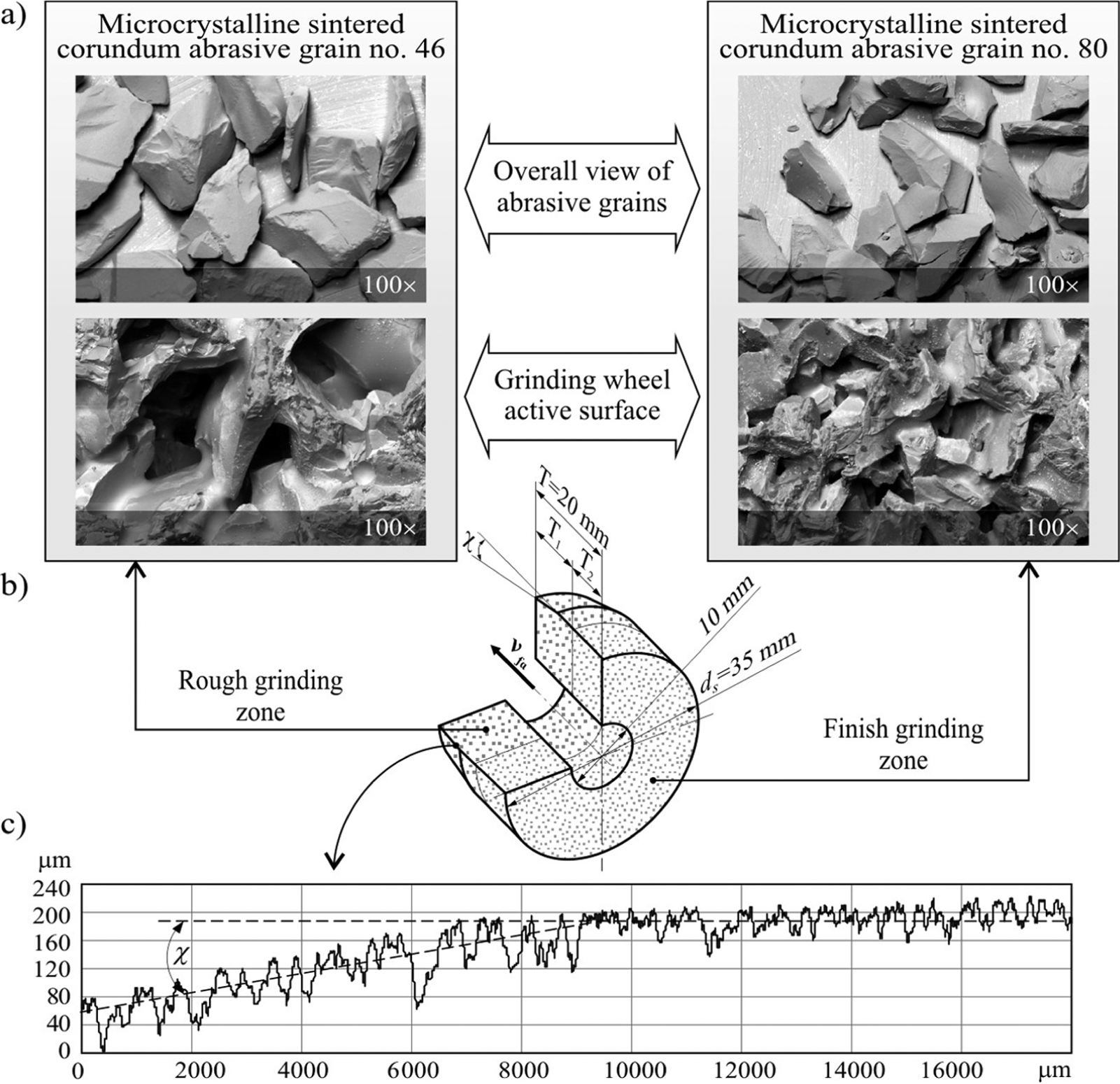
To quickly and precisely shape the conic chamfer with specific geometrical parameters on the GWAS, it was necessary to develop a special device whose construction is presented in Figure 3.
Device for precision shaping of the grinding wheel active surface: (a) functional elements and (b) view of the test-ready device.
The device was equipped with a sliding table on rollers, to which a shield casing of a single-grain diamond dresser and a micrometer screw were mounted – with the latter of these guaranteeing high-precision adoption of the desired conic chamfer angle values. The analytically determined and experimentally verified precision of the developed device is ±3% in the range of the angle values χ = 0–1.5°. 20 The device was equipped with a power transmission system composed of a table, a power supply, drive engine and toothed bar. The reciprocal movement is controlled by the contactor and the limit-switches, placed at the extreme ends of the table feed.
Precise shaping of the conic chamfer with a low angle χ required the use of a stiff sliding table and a micrometer screw for angular displacement of the plate. Also, a large space between the axis of rotation and the point of contact of the spherical tip of the micrometer screw (a = 180 mm) was provided (Figure 4). In effect, the applied scope of the chamfer angle variability χ = 0–1.5° was obtained by moving the end of the micrometer screw by 4.71 mm. During shaping of the cylindrical zone of the grinding wheel, the dresser moves along the axis of the wheel in parallel with the use of a grinder table drive. In this cut, the device table is blocked. However, during the shaping of the conic chamfer, the dresser moves at a given angle χ in relation to the axis of the grinding wheel, by using the movable table drive system of the device.
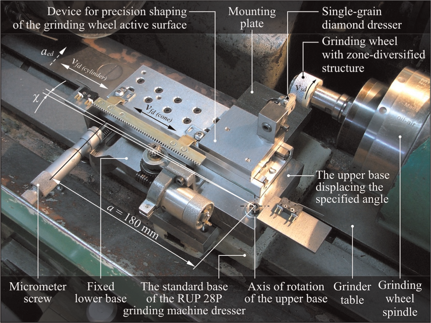
Workspace of a RUP 28P universal grinding machine with a mounted device for precision shaping of the grinding wheel active surface.
Experimental investigations
Using the developed device, tests were conducted with the aim of determining the most favourable parameters for shaping the geometric structure of the active surface of grinding wheels with zone-diversified structure designed for traverse cylindrical grinding.
Dressing methodology
The grinding wheel condition after dressing depends on the following parameters: grinding wheel peripheral speed vsd, axial table feed speed while dressing vfd and the depth of the removed grinding wheel layer aed. A single-grain diamond dresser with mass Qd = 1.25 kt and active blade width bd = 0.276 mm was used for dressing.
In the case of grinding wheels with a conic rough grinding zone, the dressing procedure was divided into two stages. In the first one, the chamfer with desired geometric parameters (χ, b) was shaped, while in the second one the cylindrical finish grinding zone was evened and sharpened. Such a division made it possible to diversify the values of axial table feed speed during the dressing of each of the grinding wheel functional zones. The application of various vfd values during the shaping of particular grinding wheel parts was supposed to increase the cutting capacity of the conic zone and provide the best possible smoothing out of the surface by the cylindrical zone.
What remained constant during the tests was the dressing engagement value (aed = 0.0125 mm) and the number of dressing passes (id(cone) = 20, id(cylinder) = 6). The grinding wheel peripheral speed (vsd = 10, 15, 20 m/s) and the dresser axial feed speed vfd were changed
during shaping of the conic chamfer: vfd(cone) = 160, 200, 240, and 280 mm/s, which corresponded to changes in the level of coverage kd = bd/fd in the range 0.17–0.10 for vsd = 10 m/s; 0.26–0.15 for vsd = 15 m/s and 0.34–0.20 for vsd = 20 m/s;
during dressing of the cylindrical zone: vfd(cylinder) = 10, 30, 50, and 70 mm/s, which corresponded to changes in the level of coverage kd = bd/fd in the range 2.75–0.39 for vsd = 10 m/s, 4.12–0.59 for vsd = 15 m/s and 5.49–0.78 for vsd = 20 m/s.
The conic chamfer angle value was adjusted to the machining allowance volume (ae = 0.1 mm) so that the grinding wheel conic zone covered the total machining allowance. The chamfer width b was selected in such a way so as to use the height of the rough grinding zone T1 to the fullest and leave some margin for the chamfer moving towards the finish grinding zone, caused by the wear. The tests were carried out using a grinding wheel with the following technical characteristics:1-35 × 20 × 10-SG/F46 K7VDG 80%/SG/F80 I7VDG 20%, whose coarse-grained rough grinding zoneconstituted 80% of the height (T1 = 16 mm). In view of the above, a conic chamfer with length b = 0.9 × T1 = 14.4 mm and value of angle χ = 0.40° was shaped on the GWAS (Figure 5).
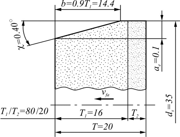
Parameter values of the grinding wheel conic chamfer χ and b.
Grinding conditions
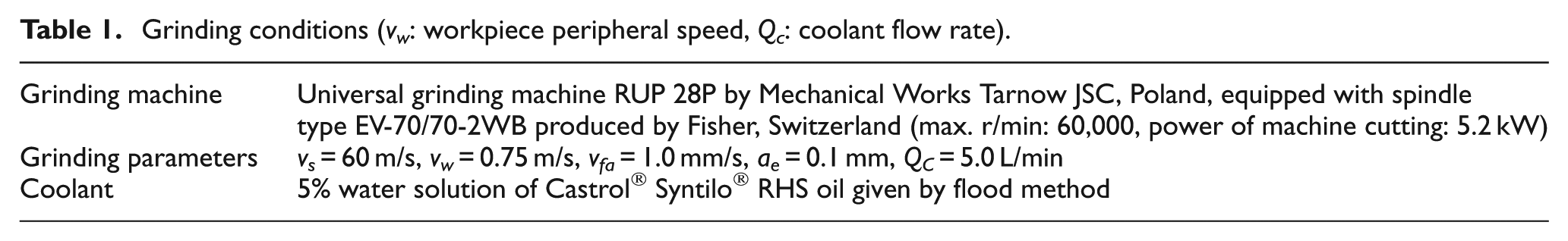
The trials of grinding with the examined grinding wheels were carried out in the internal cylindrical grinding process. The workpieces were bearing rings made from steel 100Cr6 (62 ± 2 HRC) with an inner diameter dw = 40 mm. Table 1 presents a comparison of the most important grinding parameters, accompanied by the grinding wheel and the coolant types.
Grinding conditions (vw: workpiece peripheral speed, Qc: coolant flow rate).
During the tests, both the initial and maximum grinding powers were registered, while after their termination, the axial machined surface roughness profiles were registered. The following parameters were determined on the basis of these profiles:
Ra– arithmetic mean deviation of the assessed roughness profile;
Rz– maximum height of the roughness profile within a sampling length;
RSm– mean width of roughness profile elements, within a sampling length;
Rdq– root-mean-square (RMS) slope of the roughness profile within a sampling length;
RTp– material ratio of the complete roughness profile.
Analysis of the bearing share RTp of the profile of the ground surfaces was performed using the Symmetrical Curve of Geometrical Contact (SCGC). 21 The SCGC method may be considered an alternative that offers more information in relation to evaluation of the bearing share of the RTp profile, using the Abbott and Firestone load capacity curve and parameters RTp20, RTp50. Three zones are marked in the analysis of measurements using the SCGC: top zone (T), working zone (W) and quasi-nominal zone (Q). The operating border between the vertex roughness T and working roughness W zones is determined on the basis of the evaluation of the field of contact between the roughness of the working surfaces. The T/W border indicates the value at which there is no assembly galling (the border value of the contact length 2% was adopted). The border between the working zone W and the quasi-nominal one Q runs at the height of contact equal to 98% of the sampling length.
For the purpose of multicriterion evaluation of particular GWAS functional zones after dressing, the peripheral profiles (RMS roundness deviations from mean circle were determined based on the assessment of these profiles) and microtopographies were also registered. When evaluating the GWAS and the machined surface conditions, measuring posts equipped with the following measurement instruments were used:
Multi-head measuring system Talysurf® CLI 2000 by Taylor–Hobson® Ltd (UK);
Stylus profilometer Hommel-Tester™ T8000 by Hommelwerke® GmbH (Germany);
Roundness tester Rondcom® 44 by Carl Zeiss® GmbH (Germany);
Scanning electron microscope JSM-5500LV by JEOL Ltd (Japan).
Experimental results and discussion
Figures 6–8 present the results of the research conducted on the influence of axial feed speed in shaping the conic vfd(cone) and cylindrical vfd(cylinder) zones of the grinding wheel on the surface roughness after grinding. These figures contain a comparison of the charts showing changes in the selected parameters describing the workpiece surface roughness (Ra, Rz, RSm, Rdq and SCGC zones involvement) for the grinding wheel peripheral speed vsd = 10 (Figure 6), vsd = 15 (Figure 7) and vsd = 20 m/s (Figure 8).
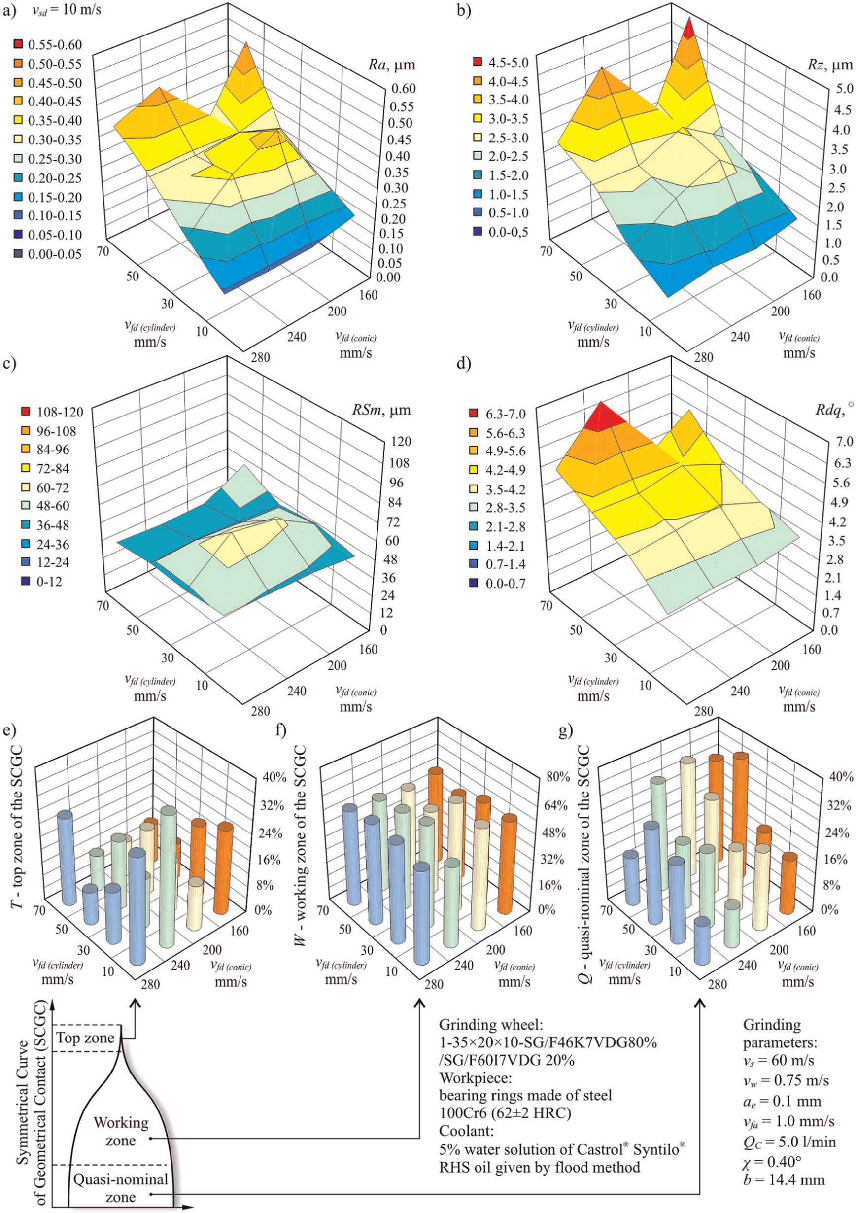
Changes in the selected roughness and SCGC parameters of the machined surface as a function of the table feed speed while dressing conical (vfd(cone)) and cylindrical (vfd(cylinder)) zones of a grinding wheel for vsd = 10 m/s: (a) Ra, (b) Rz, (c) RSm, (d) Rdq, (e) top zone of the SCGC, (f) working zone of the SCGC and (g) quasi-nominal zone of the SCGC.
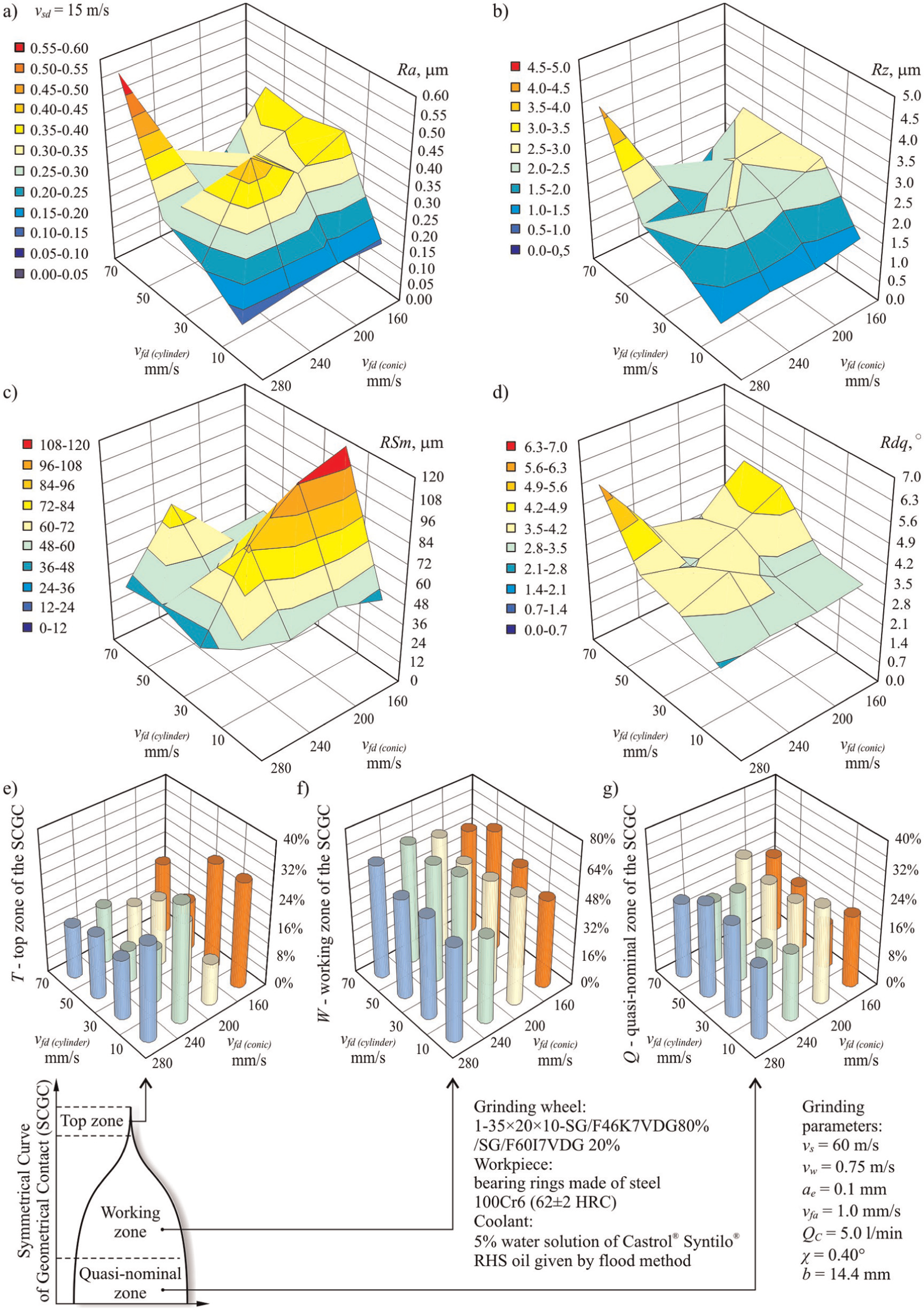
Changes in the selected roughness and SCGC parameters of the machined surface as a function of the table feed speed while dressing conical (vfd(cone)) and cylindrical (vfd(cylinder)) zones of a grinding wheel for vsd = 15 m/s: (a) Ra, (b) Rz, (c) RSm, (d) Rdq, (e) top zone of the SCGC, (f) working zone of the SCGC and (g) quasi-nominal zone of the SCGC.
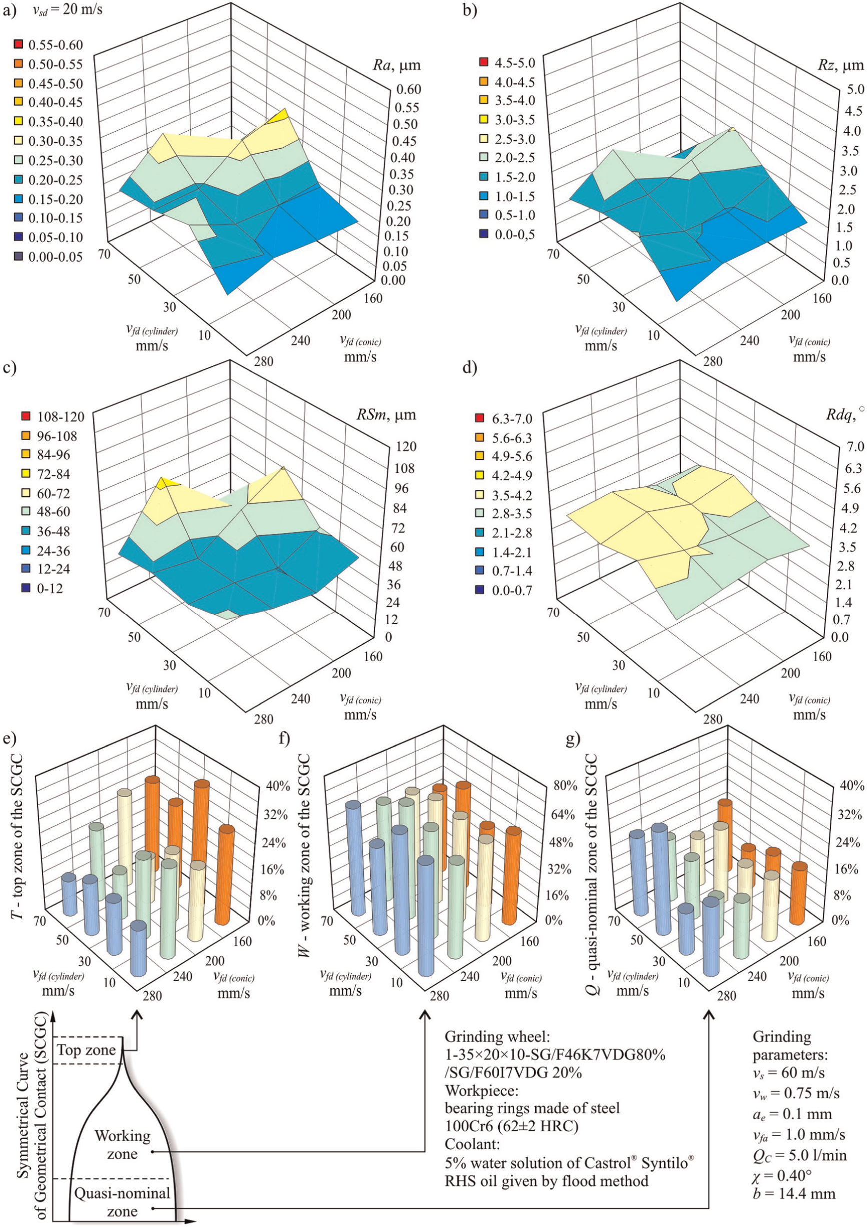
Changes in the selected roughness and SCGC parameters of the machined surface as a function of the table feed speed while dressing conical (vfd(cone)) and cylindrical (vfd(cylinder)) zones of a grinding wheel for vsd = 20 m/s: (a) Ra, (b) Rz, (c) RSm, (d) Rdq, (e) top zone of the SCGC, (f) working zone of the SCGC and (g) quasi-nominal zone of the SCGC.
A comparison of changes in the values of parameters Ra, Rz, RSm and Rdq in the axial feed speed function for shaping the grinding wheel conic zone is indicative of a considerable drop in the surface roughness of objects ground with a grinding wheel dressed with the lowest value vfd(cylinder). An almost threefold decrease of the arithmetic mean deviation of the workpiece roughness profile Ra from the values of approximately 0.50 μm with vfd(cylinder) = 70 mm/s to 0.14 μm with vfd(cylinder) = 10 mm/s was registered for vsd = 10 m/s. This tendency remains stable regardless of the speed vsd and remains constant for the whole range of vfd(cone) variability. In such conditions, the surface of the cylindrical part of the abrasive tool is shaped with the greatest covering kd. What is obtained as a result is a topography with the greatest number of kinematic cutting apexes Nkin created as a result of chip fragments of microcrystalline sintered corundum grains (Figure 10(a) and (b)). The large number of apexes obtained in this way allows for efficient smoothing out of the ground surface.
The high value of the dresser feed speed when shaping the conic chamfer vfd(cone) does not influence the workpiece surface roughness obtained in the examined process, which is mainly shaped with the grinding wheel cylindrical zone. It, however, allows for the generation of a very sharp grinding wheel surface with large intergranular spaces, which has a positive influence on the provision of the coolant into the grinding zone, as well as the removal of chips from there, which prevents GWAS smearing/loading (Figure 10(a) and (b)). Such characteristics of the conic surface area allow for more effective removal of the machining allowance and contribute to decreasing the grinding power value P (Figure 9). This tendency was clearly visible during the dressing of the grinding wheel with vsd = 20 m/s. In such conditions, increasing the feed speed during shaping of the conic chamfer from 160 to 280 mm/s allowed for a reduction of the grinding power gain ΔP from approximately 370 to roughly 200 W (Figure 9(c)).
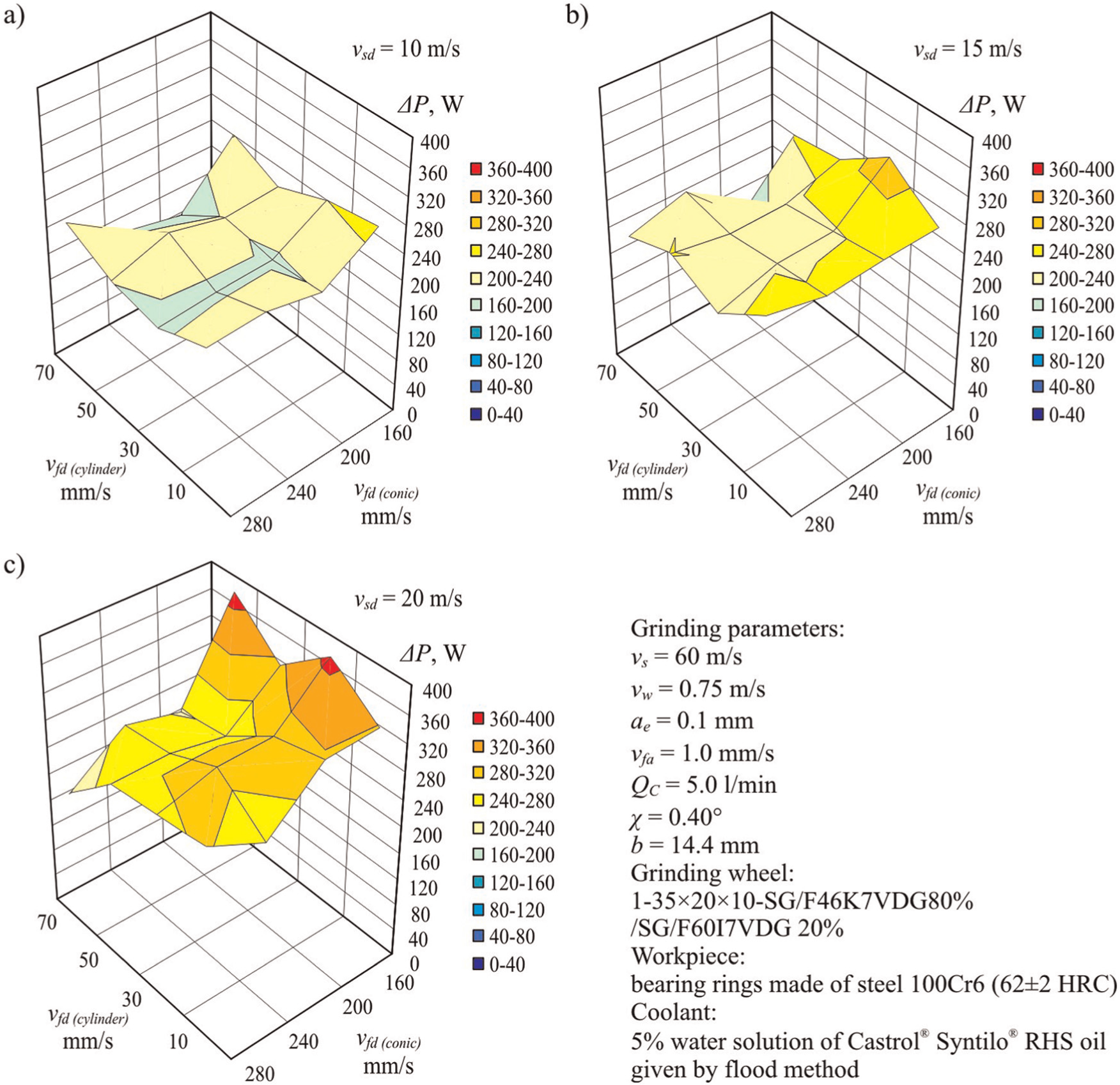
Changes in the power gain ΔP as a function of the table feed speed while dressing the conical (vfd(cone)) and cylindrical (vfd(cylinder)) zones of a grinding wheel for three values of the grinding wheel peripheral speed: (a) vsd = 10 m/s, (b) vsd = 15 m/s and (c) vsd = 20 m/s.
An increase of the feed speed for dressing the conic chamfer had a minor influence on a more advantageous volume of particular zones of the symmetrical curve of the geometric engagement. This influence of the increased feed speed is particularly visible in the results obtained at vsd = 20 m/s (Figure 8). As the vfd(cone) value increased, the height of the top zone T decreased, while the share of the working zone W and the quasi-nominal one Q expanded.
Change of the peripheral speed of the grinding wheel from 10 to 20 m/s resulted in an increase of the power consumption in the examined process (Figure 9). The calculated average values of the grinding power increase for all of the measurement points changed from 210 W with vsd = 10 m/s through 236 W for vsd = 15 m/s to 284 W, registered during the realization of the described process involving the grinding wheel dressed with vsd = 20 m/s. This increase in the calculated average values of the grinding power was a result of the increasing, as the vsd grows, value of the level of coverage kd, which led to the generation of a constantly growing number of kinematic cutting apexes Nkin.
A comparison of the microgeometry of particular functional zones of the grinding wheel is presented in Figure 10. In order to visualize the differences resulting from the adopted parameters of dressing each zone (axial and peripheral profiles), as well as SEM views and microtopographies, with active surface roughness parameters of the grinding wheel made completely from SG® grains size 46, were presented.
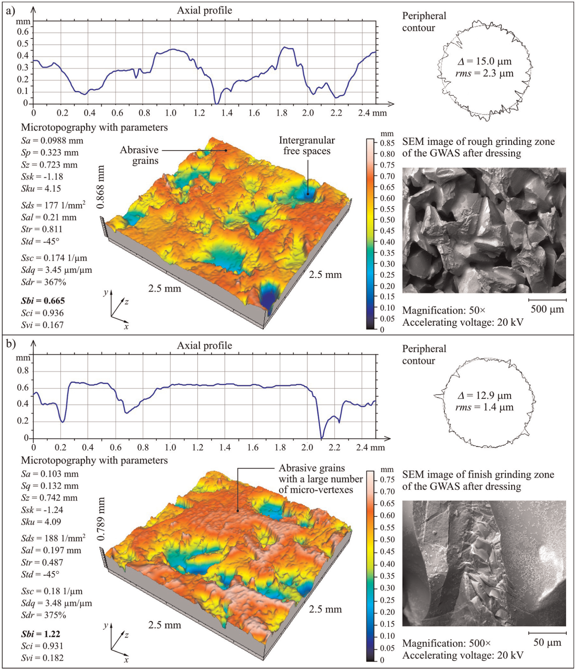
Sample axial profiles, peripheral contours, microtopography with parameters and SEM images of 46%−100% of the grinding wheel active surface after dressing at the speed vsd = 10 m/s: (a) conical zone (vfd(cone) = 280 mm/s; kd = 0.10) and (b) cylindrical zone (vfd(cylinder) = 10 mm/s; kd = 2.75).
Among the parameters describing the surface geometrical structure, the greatest difference in values, determined on the basis of microtopography of the conic and cylindrical zones, was noted for the bearing index Sbi. In the case of the GWAS shaped with feed speed vfd = 280 mm/s (kd = 0.10), the bearing index was Sbi = 0.665 (Figure 10(a)). On the basis of the microtopography of the GWAS realizing the finish grinding, shaped with the feed speed vfd = 10 mm/s (kd = 2.75), the value Sbi = 1.22 was determined (Figure 10(b)).
It can then be concluded that proper selection of dressing parameters may influence the GWAS bearing capacity expressed with parameter Sbi. An increase in the bearing capacity means that a surface with a large number of microapexes and smaller unevenness depth will be generated, that is, a microstructure adjusted to carrying out finish grinding and sparking out.
The experiments conducted indicate the possibility of adjusting the condition of particular GWAS zones to the different machining functions they help to realize. Proper selection of vsd and the high speeds of shaping the conic zone vfd(cone) allow for a considerable reduction in grinding power with a lesser increase in the machined surface roughness. The workpiece quality is most influenced by the geometric structure of the grinding wheel cylindrical zone surface, which needs to be thoroughly evened and sharpened by applying a low dresser feed speed vfd(cylinder).
An analysis of the wear of the grinding wheel with a zone-diversified structure, in which the active surface was dressed in the way described, was given in Nadolny. 22
Conclusion
The experiments carried out confirm the possibility of adjusting the GWAS condition to the machining type it realized during the dressing procedure. This property is particularly useful in the case of grinding using grinding wheels with zone-diversified structure. Different parameters for the dressing of particular functional zones on the grinding wheel make it possible to improve the conditions and results of the traverse internal cylindrical grinding process.
The range of experimental tests carried out for traverse internal cylindrical grinding using grinding wheels with zone-diversified structure allowed us to draw the following conclusion:
Proper selection of grinding wheel speed vsd and high dressing feed speed vfd(cone) during shaping of the conic zone contributes to a considerable reduction of the grinding power, with an insignificant increase in the machined surface roughness.
The workpiece quality is most influenced by the geometric structure of the grinding wheel cylindrical zone, which needs to be carefully evened out and sharpened by applying low values for the dresser feed speed vfd(cylinder).
From the adopted variable range of values connected with shaping the GWAS geometric structure, and on the basis of the obtained test results, the following values were adopted as the most favourable: vsd = 10 m/s, vfd(cone) = 280 mm/s and vfd(cylinder) = 10 mm/s.
From the adopted variable range of values for basic grinding parameters within the examined process, and on the basis of the obtained test results, the following values were adopted as the most favourable: vs = 60 m/s, vw = 0.8 m/s and b = 0.9 × T1.
Footnotes
Declaration of conflicting interests
The author declares that there is no conflict of interest.
Funding
This research received no specific grant from any funding agency in the public, commercial, or not-for-profit sectors.