
Abstract
Deterministic polishing as the final step of freeform surface machining can acquire preferable form accuracy. In this article, a deterministic polishing model based on iterative intersection tool path is presented to meet the requirement of high-form accuracy in freeform surface. In the polishing process, on-machine measurement and point set registration method are adopted for installation error extraction and form error calculation. The iterative polishing can be finished without discharging of workpiece by on-machine measurement strategy, which will reduce the processing time and improve the machining efficiency. In addition, a boundary extension method is employed to diminish the surface edge collapse generated by edge effect. Finally, the polishing experiment of freeform optical surface in an off-axial three-mirror anastigmat imaging system is conducted to verify the effectiveness of the proposed model.
Keywords
Introduction
At present, freeform surface has been applied widely in many fields due to its excellent performance, especially in ultra precision devices, such as aerospace mirror, aero-engine blades and some optical imaging systems. 1 Optical reflection mirror consisted of freeform surface in imaging system can eliminate aberration, decrease the system weight and improve the imaging quality effectively.2,3 Some materials with stable physical and chemical properties, such as glass ceramics and silicon carbide, are usually used for fabrication of optical mirror. But the processing is more difficult with the increase in hardness and fragility in material. Thus, the machining of optical element produced by hardworking material has been a focus in the field of manufacture recently.4,5
In order to acquire higher form accuracy, deterministic polishing with a sub-aperture pad is applied usually in the final machining of product with freeform surface.6,7 The form accuracy in deterministic polishing is generally related to kinematic accuracy of machine, reliability of surface data acquisition, generation of tool path, selection of machining parameters and so on.8–10 Several studies have been conducted to improve the performances, such as preferable efficiency and less edge effect, in polishing. Cao and Cheung 11 carried out an in-depth research on contact mechanics, wear mechanisms and theory of kinematics in bonnet polishing to reach an insight of material removal characteristics. Based on the predicable polishing process, the polishing parameters are optimized successfully. Pilný and Bissacco 12 presented an automatic monitoring system in the machine process with integrated sensors in robot-assisted polishing which will acquire a stable polishing process and a better surface quality. Yin and Zhang 13 proposed an improved chemical mechanical polishing (CMP) method to eliminate tool marks in polishing process of planar and aspherical aluminum mirrors. But the polishing efficiency is not considered sufficiently in this article. Several contact pressure distribution models are compared in edge polishing by Zhou et al., 14 and a more accurate equation of material removal is presented. The influence factors of edge effect are also analyzed, but the defect in edge area cannot be eliminated. Satake et al. 15 proposed a stacked polishing pad with a thin upper layer and a hard thin lower layer by investigating the properties of polishing pad, which will increase the flatness of surface edge in the polishing process effectively. Chaves-Jacob et al. 16 realized the compliance control of radial force on a five-axis computer numerical control (CNC) machine for pre-polishing, and the tool path optimization is also conducted. Hereby, a force-controlled polishing is employed to obtain a more accurate material removal in this article. Zhang et al. 17 made a review of machine vibration in ultra precision machining, and the influence of machine vibration on surface generation is also analyzed. Li and Gu 18 reviewed the freeform surface inspection techniques in detail, including measurement methods and description of measurement data. Lee and Mou 19 presented a model of decoupling both types of measurement error in automated inspection of freeform surface, which increases the accuracy of surface data acquisition efficiently. The material removal influenced by different polishing tool path, such as scanning,20,21 bi-scanning, 22 Hilbert or Peano paths, 23 is studied by Tam and Cheng. 24
Installation error will induce a deviation between measured results and actual surface in measuring process. Calibration is usually introduced to reduce the installation error, which will spend lots of time. By adopting point set registration method, such as iterative closest point (ICP), the installation error can be extracted by the transformation matrix
Deterministic material removal is a critical issue of ultra precision surface form acquisition in the process of deterministic polishing. Generally, the material removal model in polishing is based on Preston equation which indicates that material removal rate is related to the contact pressure, relative sliding velocity, polishing dwell time, parameters of workpiece and polishing tool. Yang and Lee 27 researched the material removal rate of aspherical lens polishing using spherical tool, and the effect of aspherical surface curvature on the local material removal rate is discovered. Fan et al. 28 presented a model of material removal profile perpendicular to the tool path, and the polishing dwell time of the whole surface is acquired. Song et al. 29 take the surface residual error and machine dynamic limitations into account simultaneously to acquire a single optimization problem. By solving the constrained optimization model, the velocity map which satisfies the movement limitations of machine is acquired and the surface error is reduced in the machining process.
The research approach of this article is presented with a flowchart, as illustrated in Figure 1. The form accuracy of freeform surface is improved in iterative polishing. In measuring process, the form error and installation error are obtained according to on-machine measurement and point set registration method. Based on the measured surface profile, the intersection tool path is generated, and the tool dwell time is calculated. After that, the polishing process is conducted complying with the tool path and the tool dwell time to finish one iteration. The polishing result is iterated repeatedly based on the circulation mentioned above and the iterative polishing will not be terminated until the form accuracy of freeform surface meets the requirement.
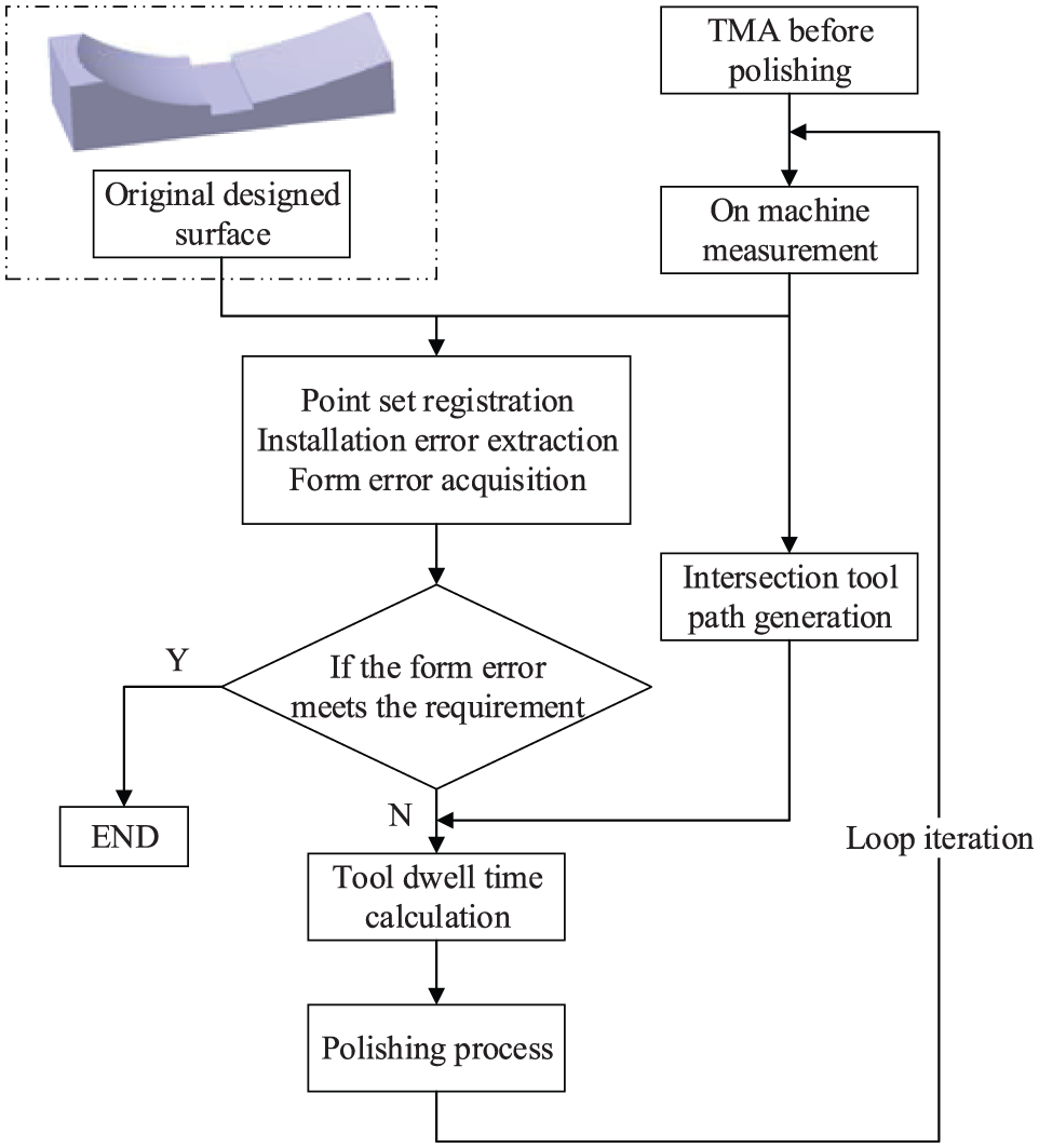
Circulation of iterative polishing.
The rest of this article is structured as follows: in section “Freeform surface on-machine measurement and installation error extraction,” the measuring process and the installation error extraction method are presented; in section “Iterative intersection tool path of freeform optical surface,” the iterative intersection tool path and deterministic polishing is introduced in detail; the polishing experiment of glass ceramic three-mirror anastigmat (TMA) is conducted in section “Polishing experiment verification and discussion”; and the conclusion is provided in section “Conclusion.”
Freeform surface on-machine measurement and installation error extraction
Description of freeform surface in off-axial TMA imaging system
The application of off-axial TMA can improve resolution, enlarge view field and reduce the system weight effectively in imaging system.30,31 According to the freeform surface construction of primary mirror, tertiary mirror or secondary mirror, the performance of the TMA will be further improved. Figure 2 shows the structure of the TMA. The primary mirror (mirror 1) and tertiary mirror (mirror 3) are integrated as an integral to facilitate the installation and adjustment process. However, the relative location of the two mirrors must be achieved in fabrication, which makes the machining much more difficult.
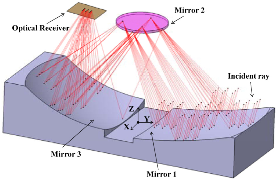
Structure and principle of TMA imaging system.
The schematic diagram of the TMA imaging system is also expressed in Figure 2. The primary mirror and tertiary mirror are designed as freeform surface for superior imaging performance. In this article, XY polynomial (XYP) is used for optical freeform surface fitting, which can simplify the calculation process, such as normal vector and the closest point. 32 The polynomial can be expended into monomials of xmyn, and the sum of m and n is ⩽10.
The general expression of XYP is 32
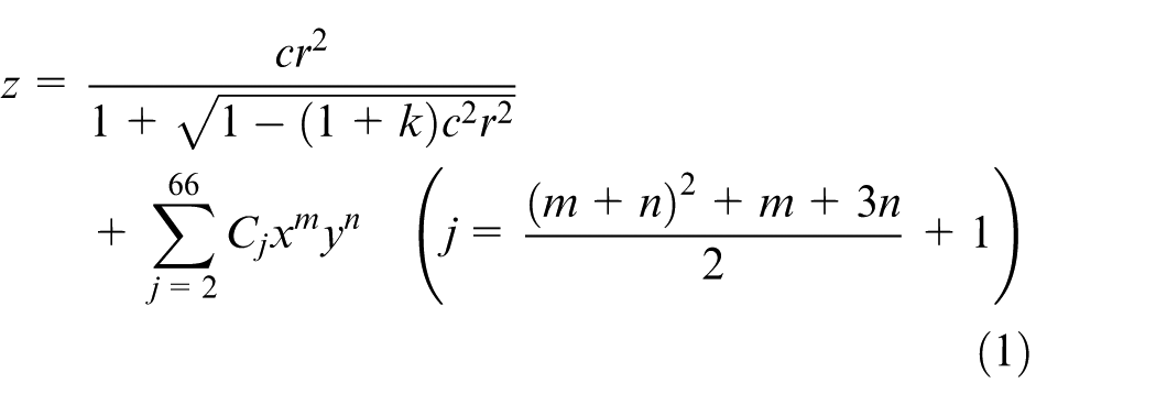

where z is the sag of the surface parallel to the z-axis, c is the vertex curvature, k is the conic constant and Cj is the coefficient of the monomial xmyn. When the parameters are calculated in freeform surface fitting process, the expression of XYP can be simplified as equation (2). The coordinate of point on XYP surface can be expressed as (x, y, z).
Freeform surface on-machine measurement
In this article, on-machine measurement is adopted for freeform surface form acquisition to avoid the repetitive installation in iterative polishing. The measured result is also used to calculate the allowance for next iterative polishing process. The restriction still exists in noncontact measurement of optical freeform surface. Therefore, the contact measuring instrument with a probe is employed for acquiring surface data accurately. The procedure of freeform surface contact inspection is shown in Figure 3.
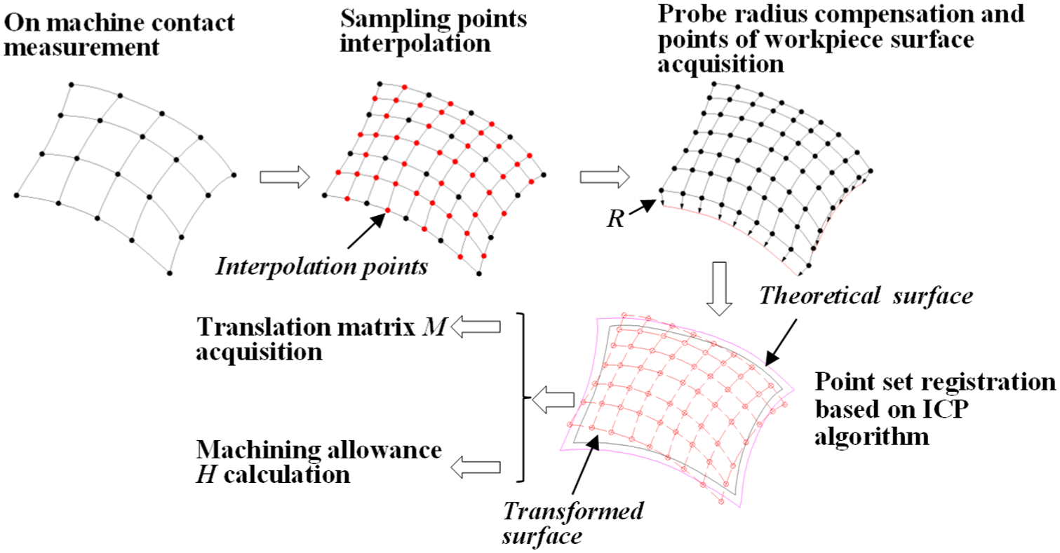
Procedure of freeform surface contact inspection and machining allowance calculation.
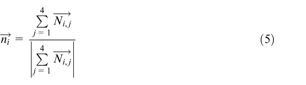
The result of contact inspection is the coordinate of probe tip center. Therefore, the radius compensation is indispensable for the measured surface data, which needs information of normal vector of each sampling point. In general, the normal vector is obtained through surface interpolation or fitting by B-spline method, Coons’ method or nonuniform rational B-spline (NURBS) method. 33 The data point after radius compensation can be acquired by

where
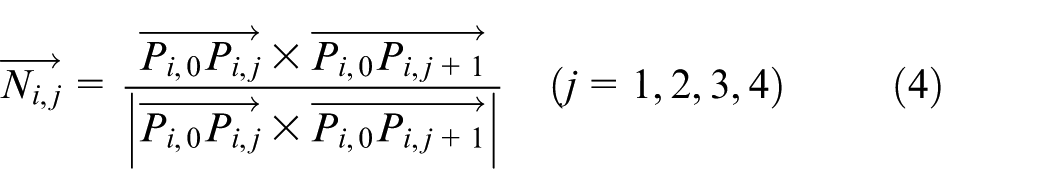
therefore, the normal vector
Installation error extraction based on ICP algorithm
Installation error will induce a deviation between measuring coordinate system and actual surface, which will generate an incorrect estimate of machining allowance. In order to acquire preferable form accuracy, the installation error must be reduced. When the surface profile of workpiece is closed to theoretical surface, the installation error can be substituted for the deviation of them. By adopting point set registration method, the deviation of workpiece and theoretical surface will be obtained, and the transformation matrix
ICP algorithm is employed in the point set registration process. The object of point set registration is searching for a transformation matrix to reduce the deviation between measured data of workpiece and theoretical model at utmost. Based on the principle of least squares, the formulation is given here for transformation matrix calculation
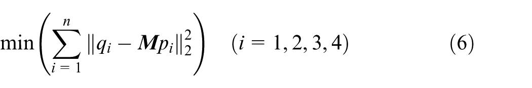
where n is the number of measured points, pi is the measured point, qi is closest point on theoretical surface related to pi and
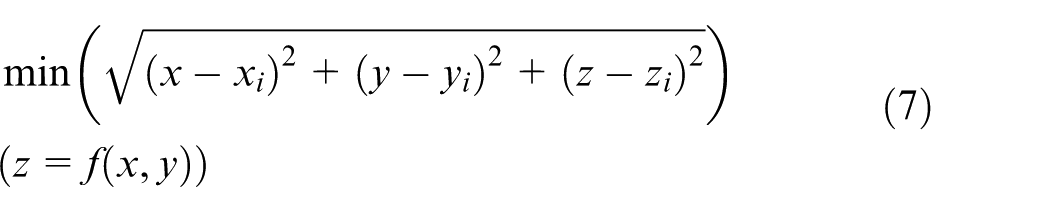
where (xi, yi, zi) is the coordinate of measured point pi and (x, y, z) is the coordinate of point qi related to point pi. Equation (7) is an unconstraint optimization problem, and the unique optimal solution can be acquired definitely in geometrical terms. The transformation matrix
where
Iterative intersection tool path of freeform optical surface
Iterative intersection tool path generation
The form accuracy and processing efficiency are closely related to the tool path generation in freeform surface polishing. At present, single tool path, such as scanning path, bi-scanning path or Peano path, is usually adopted for freeform polishing. However, the edge effect and inefficient material removal rate restrict the employment of single tool path seriously. Therefore, the intersection tool path is proposed for deterministic polishing to improve the form accuracy. As shown in Figure 4, the tool paths along axis x and axis y are generated, and the two kinds of paths with different polishing directions are applied alternately in each iterative polishing. Figure 4 shows the principle of iterative polishing. The peak and valley of surface topography after two contiguous iterative polishing steps are exchanged according to offsetting the tool path along the y or x direction by half of the path spacing (d/2), which will increase the material removal rate effectively and reduce the form error of the workpiece.
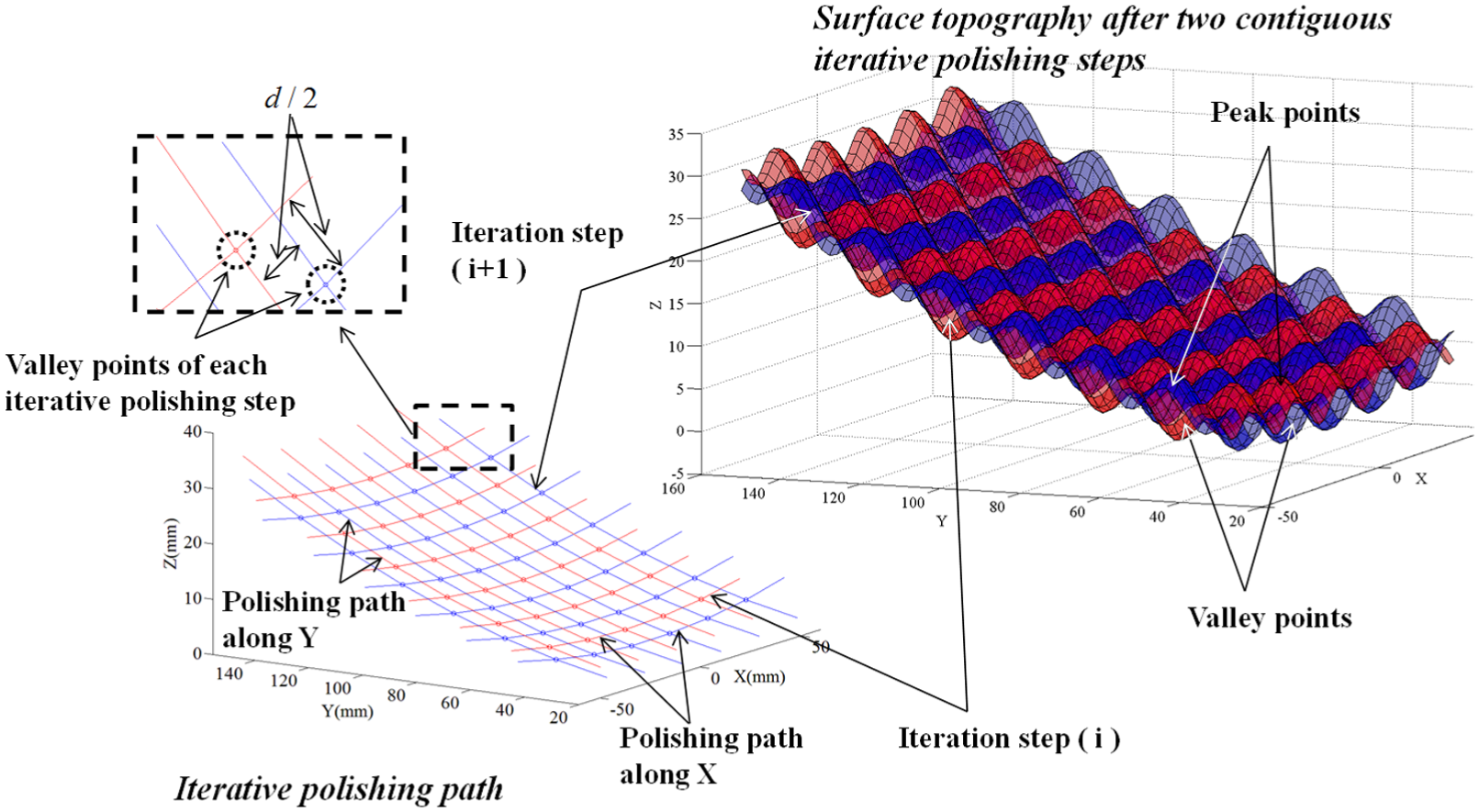
Principle of iterative polishing based on the intersection tool path.
Based on the surface form feature of TMA, the iterative intersection tool path is projected, as shown in Figure 5. In general, the tool path in surface edge is connected by a straight line, which will generate a sharp angle transition. Due to the movement limitation of CNC machine, vibration and deviation will arise in area of sharp angle transition of tool path, and the quality of polished mirror will be decreased. Therefore, transition of circular interpolation is introduced in the sharp angle transition area to enhance the kinetic stability of CNC machine, as shown in Figure 5. Considering the discontinuity of boundary in mirror 1, as shown in Figure 2, the parabolic interpolation is also applied for connection of tool path.
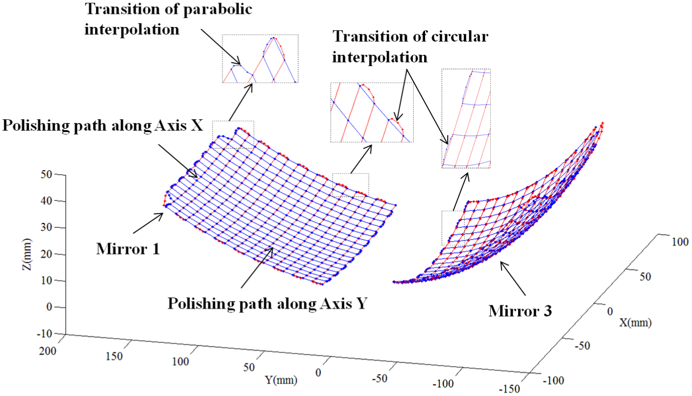
Iterative intersection tool path of TMA processing.
The edge effect can also be restrained effectively based on the intersection tool path. The polishing tool path along axis x traverses the border of tool path along axis y, and the situation is analogical in another direction, as shown in the tool path transition area of Figure 5. Therefore, the polishing of surface edge area is conducted only once in the two contiguous iterative polishing steps, which will reduce the collapse of edge area to some extent.
Tool dwell time calculation in freeform surface polishing
The material removal should be predictable if the polishing procedure is employed as the final step of freeform surface machining to reach the desirable form accuracy. In polishing process, the rotation speed of polishing tool and normal force are defined as the constant. Therefore, the material removal in each polishing spot is only influenced by feed speed. Figure 6 shows the schematic diagram of freeform surface polishing with a spherical polishing tool. The local coordinate system is built on arbitrary polishing spot, and the origin of the coordinate is located at the center of contact area. Axis y is parallel to the tangent vector of tool path, and axis x is parallel to the normal vector of polishing spot. In coordinate system Oxyz,
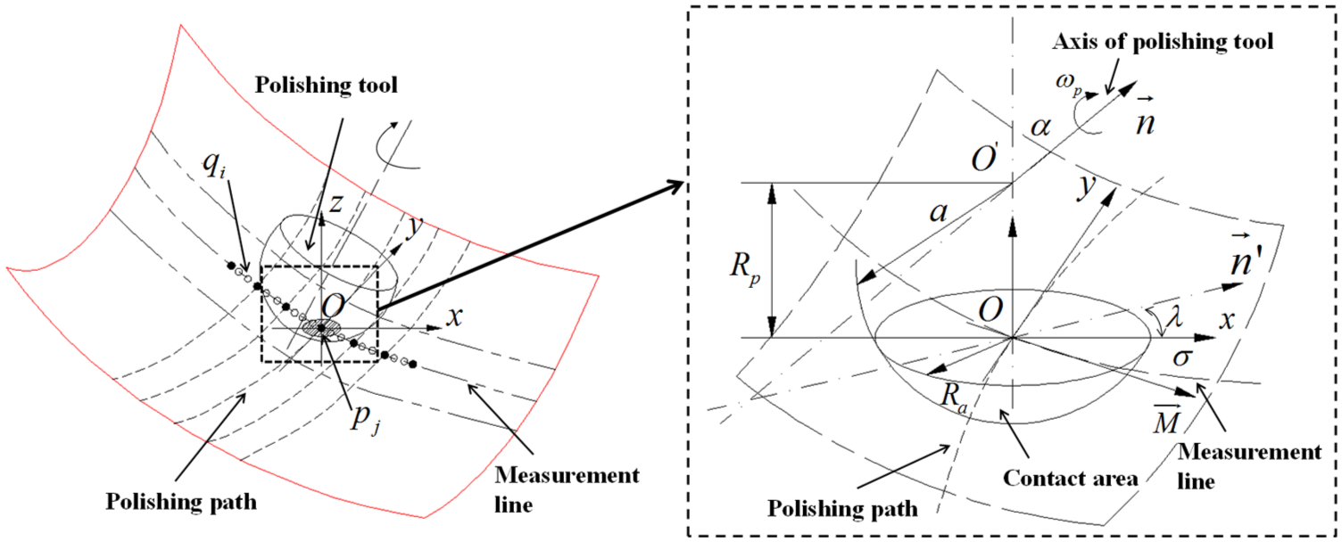
Schematic diagram of freeform surface polishing with spherical polishing tool.
The ratio of principle curvature Rmin and Rmax in theoretical surface of TMA is <1/5. Therefore, the pressure distribution in the contact area can be expressed based on the Hertzian contact theory 34 approximately as
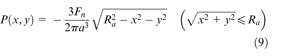
where Fn is the normal pressure, a is the radius of polishing tool and Ra is the radius of contact area. According to the local material removal theory of polishing, the relative velocity between polishing tool and workpiece is deduced by Fan et al. 28 in coordinate system Oxyz as
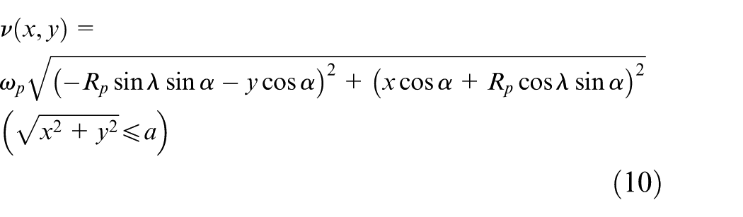
where ωp is the spindle revolutions and Rp is the distance between spherical polishing tool center O′ and original point O. Based on Preston equation, the polished profile perpendicular to tool path can be obtained by Fan et al. 28 as
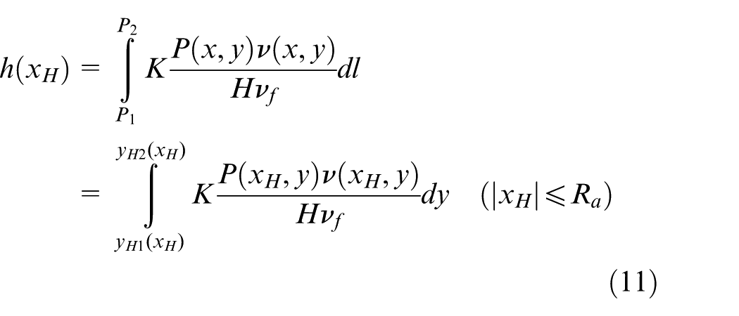
where h is the depth of material removal, K is the Preston coefficient, P is the pressure in the contact area, H is the hardness of part surface and νf is the feed speed of polishing tool. P1(xH, yH1) and P2(xH, yH1) are endpoints of tool path within the contact area, as shown in Figure 7. Substituting equations (9) and (10) into equation (11) yields
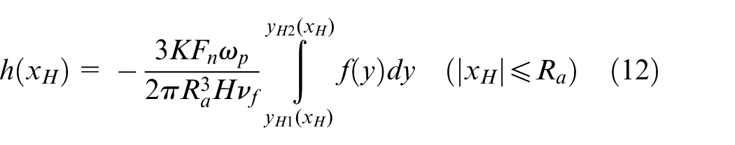
where

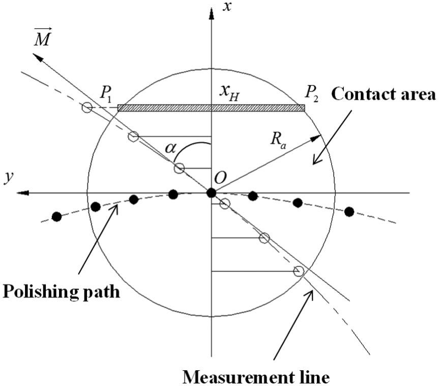
Material removal perpendicular to tool path in contact area.
As shown in Figure 6, pj is the polishing dwell point and qi is the measurement point for calculation of tool dwell time. When qi does not belong to axis x, the polishing depth of qi related to polishing dwell point pj can be expressed approximately as
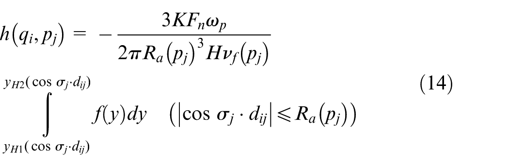
where σj is the angle between measurement vector
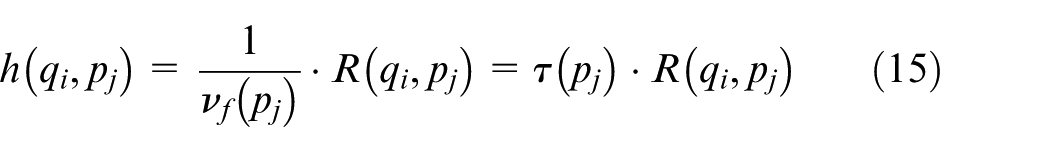
where τ(pj) is the inverse of the feed speed of polishing tool on point pj and R(qi, pj) can be regarded as the influence coefficient of material removal on measurement point qi related to polishing point pj. Only when cos σj·dij is less than radius of contact area of point pj, will the material removal of point qi related to point pj be achieved. Thus, R(qi, pj) can be expressed as
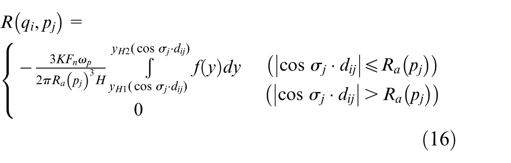
On measurement point qi, the total polished depth is the superposition of material removal on each polishing dwell point in corresponding measurement line. Thus, the polishing depth Hj of measurement point qi can be expressed as
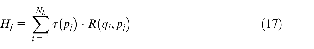
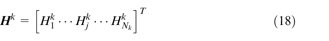
where Nk is the number of polishing dwell point. The polishing depth of all measurement points in the kth measurement line can be expressed as
Therefore, the polishing dwell time in the kth measurement line can be calculated by
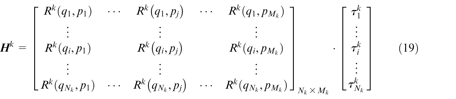
where Mk is the number of measurement point in the kth measurement line. Equation (19) can be abbreviated as

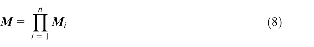
The polishing dwell time of the entire freeform surface can be expressed as
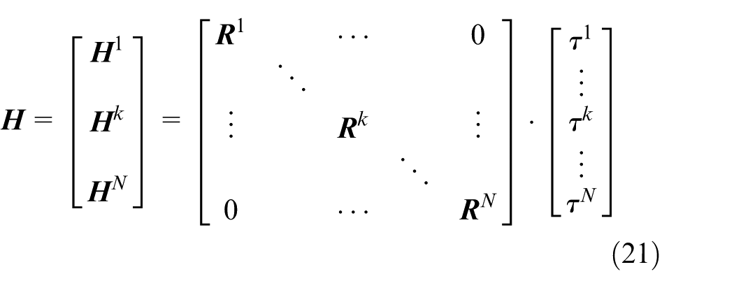
where N is the number of measurement line. And equation (21) can also be abbreviated as

The polishing dwell time
where
Polishing experiment verification and discussion
Introduction of experiment equipments
The polishing experiment of glass ceramics TMA is conducted on a four-axis CNC platform with an on-machine measurement module, as shown in Figure 8. The size of the TMA is 320 mm × 120 mm with depth of mirror 1 is 30 mm and mirror 3 is 45 mm. The hardness of glass ceramics is 8.3 GPa, which is acquired by nano-indentation experiment. The polishing motion is realized by the two rotational axes (B-axis and C-axis) and the two translational axes (X-axis and Z-axis). The positioning accuracy of axis B is 2arcsec and axis C is 2arcsec. The two translational axes (X-axis and Z-axis) are fabricated by linear motor with the positioning accuracy of 2 µm. The polishing tool and the measurement device are installed on the rotational platform of axis B. The TMA is fixed on the rotational axis C. In the measuring process, axis Z and axis B are fixed, and the measurement direction is always parallel to axis Z. A pressure sensor is introduced on the end of polishing spindle to realize constant force in polishing process. The axial force F is set to 10 N. The radius of the spherical polishing tool which is made of tough sponge is 16 mm. The rotational speed of polishing tool is set to 104.72 rad/s, and the polishing angle α is set to 15°. The polishing slurry is CeO2 solution with the volume concentration of 20%, and the size of diamond abrasive paste adopted in polishing process ranges from 6 to 0.5 µm. The tool path of mirror 1 is generated with 127 (in the x direction) × 113 (in the y direction) and mirror 3 is 121 (in the x direction) × 103 (in the y direction).
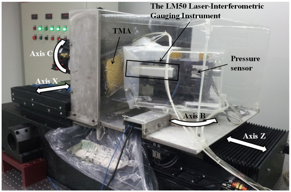
CNC platform for TMA polishing with on-machine measurement system.
The LM50 laser-interferometric gauging instrument with resolution of 1 nm is adopted in the process of on-machine contact measurement, as shown in Figure 9. The repeated accuracy of LM50 is 0.2 µm, which has been calibrated by a standard planar mirror. To give consideration of measuring efficiency and accuracy comprehensively, 2601 (51 × 51) measurement points are adopted for surface form acquisition in the measuring process. A space with 0.5 mm is reserved in surface edge area to avoid the random error. The experiment is conducted in an ultra-clean chamber with constant temperature to improve the stability of measuring process. The ambient temperature is set to 20 °C (±0.5 °C). To inspect whether the surface roughness meets the requirement, the Form Talysurf PGI 1240 with the stylus radius of 2 µm is employed after iterative polishing process. The iterative polishing is finished with the installation of TMA once. Therefore, the surface roughness of polished TMA before and after each iterative polishing cannot be acquired.
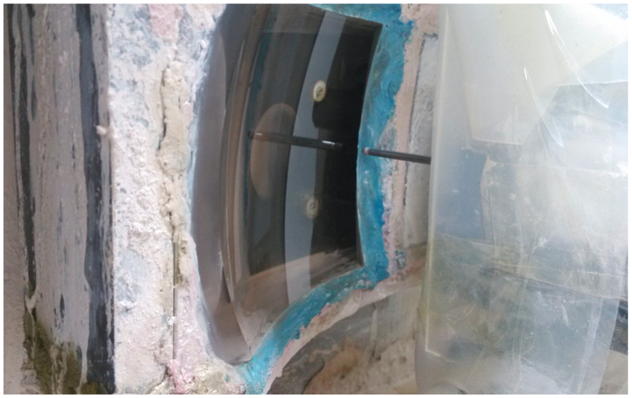
On-machine contact measurement in iterative polishing process.
In order to decrease the error generated by edge effect, the boundary of TMA is extended. As shown in Figure 10, a wooden frame is introduced on the periphery of TMA, and a groove with 5 mm wide and 10 mm deep is reserved. Then, the groove is filled with putty according to the tangent direction of borderline of TMA. Thus, the boundary of TMA is extended by the putty in groove. In addition, the extended boundary can also prevent the interference of polishing movement on surface edge area.
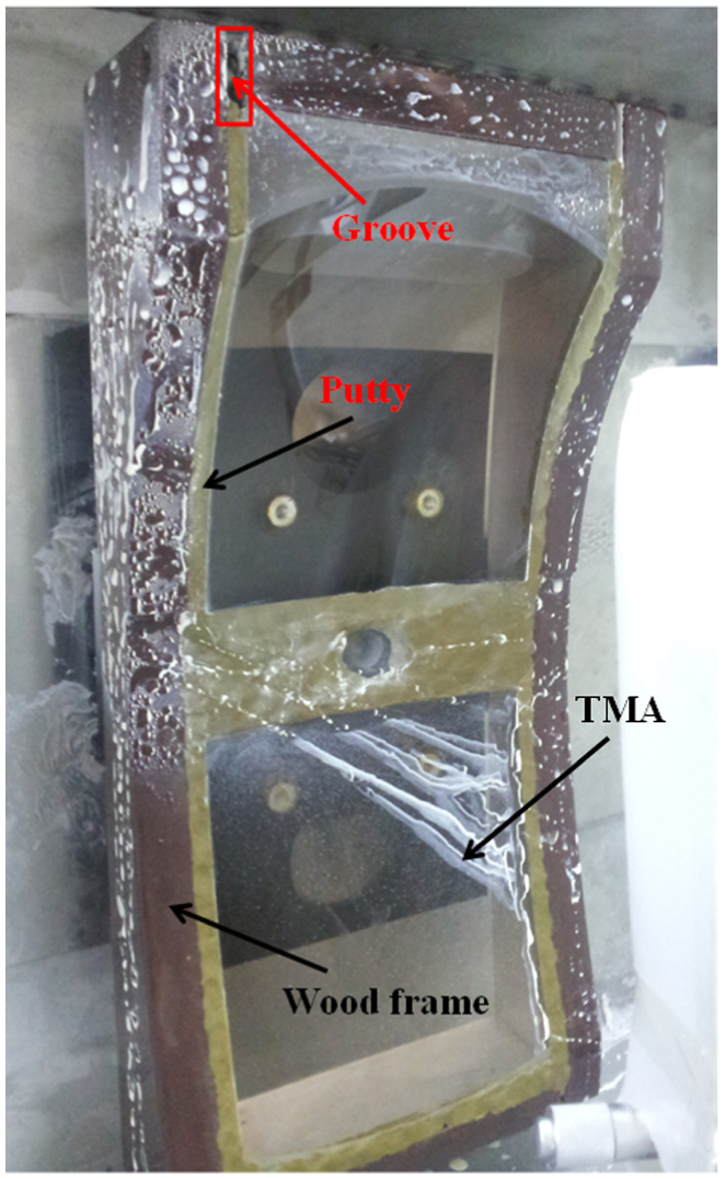
Boundary extension of TMA with a wooden frame.
Experiment results and discussion
In the polishing experiment of glass ceramic TMA, Rk in equation (19) can be calculated according to the given experimental parameters. The Preston coefficient K is acquired by fixed-point polishing experiment with the same experimental conditions in advance. In order to make the machining coordinate system consistent with TMA, tool path Po should be transformed based on matrix

where Pt is the transformed tool path. Allowance Hk in equation (19) in each iterative polishing is acquired by on-machine measurement with LM50 and point set registration process. As
The maximum deviation of surface form (mirror 1) is reduced rapidly with the increase in iterations, as shown in Figure 11(a). The declination of absolute mean deviation is also presented in Figure 11(b). Furthermore, the size of abrasive paste and the polishing time consumed in polishing process is shown in Figure 11(c). In iterative polishing with iterations from 0 to 2, the reduction of absolute mean deviation is more apparent than the maximum deviation, which is caused by defection in polishing process with rough abrasive paste. In order to remove the major deviation fleetly, the polishing time consumed in the two initial iterations is much more than the subsequent iterations. After 8 times of iterative polishing, the peak deviation of mirror surface form is removed and the absolute mean deviation is reduced to a stable stage relatively with declination of abrasive paste size. Then, the maximum deviation is reduced to 15 µm, and the form accuracy has met the requirement. The last iterative polishing steps (iterations from 8 to 12) are conducted without abrasive paste (the size is 0 in Figure 11(c)) to remove the scratch generated above. As a result of elimination of scratch and defection, the form accuracy in maximum deviation is improved in the final stage of polishing. However, the absolute mean deviation only fluctuates around a definite value. After 12 times of iterative polishing, the maximum deviation of mirror surface form is reduced from 39.9 to 11.6 µm, and the absolute mean deviation is reduced from 4.88 to 1.90 µm. The distribution of deviation before and after polishing process is shown in Figure 12. The polishing result demonstrates that the collapse generated by edge effect is slight. In addition, the form accuracy of mirror is improved effectively, especially in the edge area. About 140 h is consumed in total in the iterative polishing of mirror 1 without consideration of on-machine measurement. The roughness of the polished mirror can reach to 6.7 nm (mirror 1), which is acquired by off-line measurement on Form Talysurf PGI 1240. The polished glass ceramics TMA is shown in Figure 13.
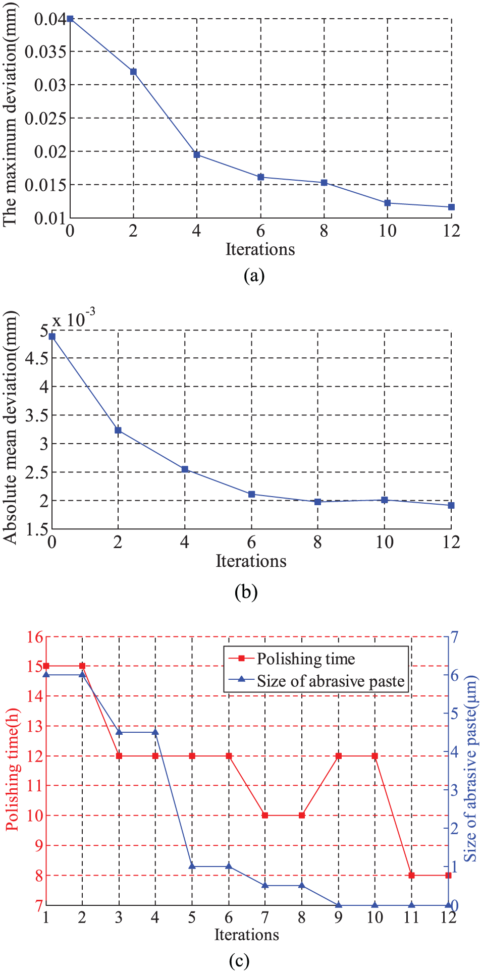
Polishing results and experiment conditions with the increase in iterations: (a) variation of maximum deviation, (b) variation of absolute mean deviation and (c) polishing time and size of abrasive paste.
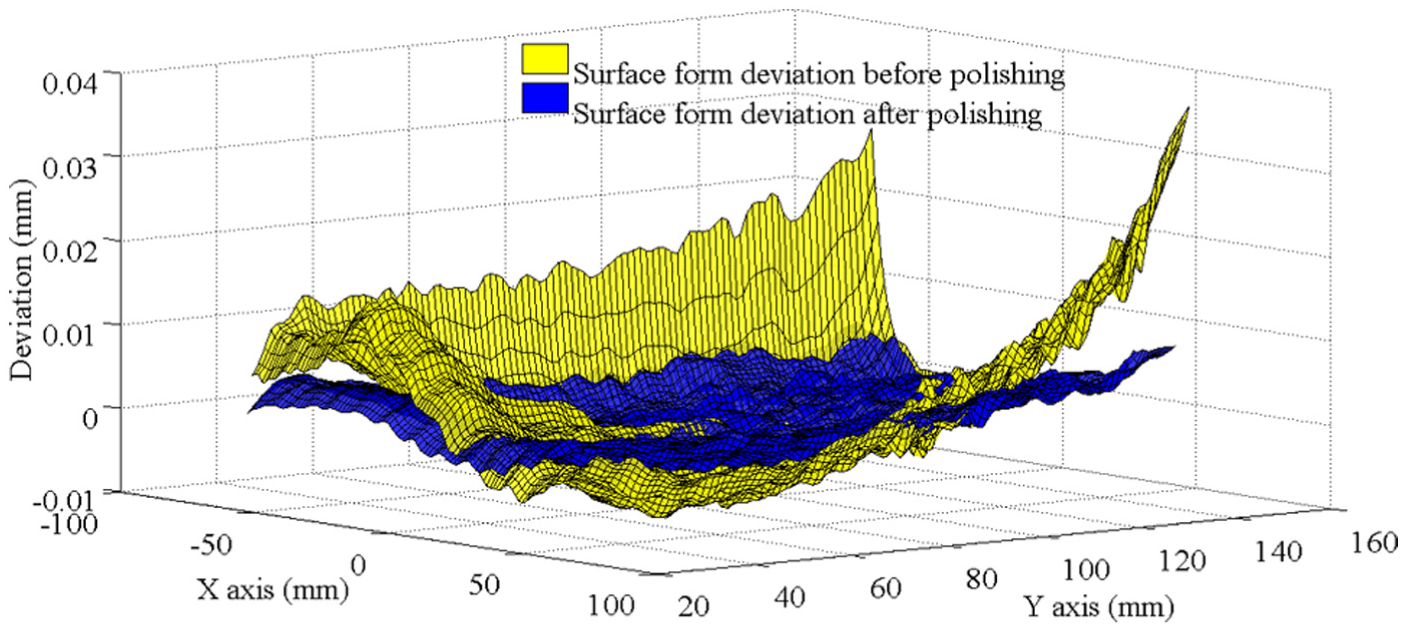
Distribution of surface form deviation before and after iterative polishing.
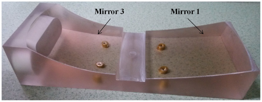
Polished surface of glass ceramic TMA.
Conclusion
In this article, the deterministic polishing based on iterative intersection tool path is proposed for form error modification of freeform surface. In the polishing process, the edge effect can be reduced by the proposed intersection tool path and the extended surface boundary. In order to reduce the error generated by repetitive installation, on-machine measurement is employed to realize iterative polishing without discharging of workpiece. Based on point set registration method, the installation error is extracted, and the complex calibration procedure can be avoided. The polishing experiment of glass ceramic TMA is conducted with the proposed method. The maximum form deviation of mirror 1 can be reduced from 39.9 to 11.6 µm after 12 times of iterative polishing, and the distribution of surface form deviation is uniform. In edge area, the collapse generated by edge effect is slight. Besides, the roughness of the polished surface (mirror 1) can reach to 6.7 nm, which has met the requirement of usage in optical reflector. The experiment results show that the proposed polishing method can obtain a preferable accuracy of surface form with negligible edge effect.
Footnotes
Declaration of conflicting interests
The author(s) declared no potential conflicts of interest with respect to the research, authorship and/or publication of this article.
Funding
The author(s) disclosed receipt of the following financial support for the research, authorship, and/or publication of this article: This work was supported by the National Key Basic Research and Development Program (973 program) of China (Grant No. 2011CB706702) and Jilin Province Science and Technology Development Plan Item (Grant No. 20130101042JC).