
Abstract
An experimental investigation of the cutting performance in hybrid laser–waterjet (or laser-assisted waterjet) micro-grooving of germanium wafers is presented, with a view to eliminate or minimize the laser-induced thermal damages to the workpiece. Various process parameters are considered, such as water pressure, laser pulse overlap, pulse energy and focal plane position. It is found that the hybrid laser–waterjet is a viable technology for micromachining of germanium with negligible thermal damage. A Raman spectroscopy study did not reveal any crystalline change in the material on the machined surfaces. The effects of process parameters on the heat-affected zone and groove characteristics are amply discussed. It is shown that good grooves of within 100 µm in top width and up to 300 µm in depth can be machined with high material removal rates, and the heat-affected zone size can be controlled to within 20 µm on each side of the grooves. Recommendations are also made on the appropriate process parameters that may be used in the process.
Introduction
As a semiconductor material, germanium (Ge) attracts considerable attention due to its increasing importance in many applications. Comparing with silicon (Si), Ge is suitable for high-performance systems and high-speed devices due to its substantially high electron and hole mobility. 1 It has been intensively used in many fields including electronics, infrared optics, solar electric applications and fibre-optic systems.1–3 However, as a brittle material, Ge gets fractured easily, and its processing becomes a challenge. 4 Diamond micro-grooving 5 and ultrasonic elliptical vibration cutting 3 have been employed to micro-machine Ge in its ductile regime to reduce fractures. However, since the critical depth for ductile-to-brittle transition when cutting Ge is reported to be less than 2 µm, the efficiency of these cutting methods may be low. When considering non-mechanical machining, it is much more inefficient and difficult to carry out chemical etching on Ge than on Si, because a high etching anisotropy is required to produce V-grooves on Ge, as well as specific acidic etchant and special mask.2,6 Good performance in Ge slicing has been reported using wire electro-discharge machining in which wastage can be reduced by proper thin wire, but the low slicing rate, for example, typically taking 15 h to slice a 66-mm diameter wafer, remains to be improved. 4
By contrast, lasers offer a good potential in Ge micromachining, as well as silicon and other hard-brittle materials.7–11 Laser machining is realized by locally heating, melting and vaporizing the irradiated material through supplying a high-energy intensity in a small area. However, as a thermal process, laser machining introduces undesirable thermal damages typified by heat-affected zone (HAZ), which results in decreases in both reliability and functionality of the final products, particularly in micromachining where the thermal damage may be over the entire micro-structure.
Ultra-short pulsed lasers have been used in machining to reduce thermal accumulation and conduction towards the bulk material. It has been reported that the ultrashort-pulsed lasers, such as femtosecond lasers, is able to realize athermal ablation with clean machined micro-features where HAZ is negligible.7,8,12 Whereas ordinary lasers remove the material through the molten area ejection and vaporization, a femtosecond pulsed laser breaks the atomic lattice directly and completes material removal by vapour ejection in a very short pulse duration before the heat is conducted into the surrounding area. However, at this stage of development, ultrashort-pulsed lasers are associated with low material removal rates (MRRs) due to the high photon cost and low available power.
Considerable research has been made to use the cooling effect of water to minimize the thermal damages in laser machining. Water has been used in laser machining in several ways, including a thin water layer covering the workpiece such as underwater laser machining, 13 as well as thin steam 14 or sprayed water layer 15 flowing slowly over the workpiece. It was reported 13 that the thin water layer can reduce the thermal damage and improve the cutting quality. However, the water layer as well as the debris and bubbles generated in water during the process reduce the laser beam quality and the laser energy transferred to the work surface. By contrast, the slowly flowing steam or water layer offers a less effective cooling ability in addition to its effect on the laser beam quality.
Water has also been introduced in the form of a jet to the laser cutting process. In an effort to overcome the small laser focal depth and increase the thin laser beam travel distance, a laser-microjet (or waterjet-guided laser) technology has been invented. It has been claimed that this technology allows a laser beam to totally reflect and travel inside a thin waterjet which acts like an optical fibre and yields high MRR with negligible HAZ. 16 As long as the laser beam can be conducted by a continuous waterjet flow, the laser-microjet can cut material regardless of the laser focal depth which typically ranges from a few millimetres to around a centimetre. However, some considerations may need to be made in using this technology. First, the laser wavelength must fall into the water transmission spectrum, 17 thus it may be difficult to make the optimum selection of a laser for a given material. Second, since this technology has been claimed to rely on the full reflection of the laser beam inside a thin waterjet, the water atomization and waterjet breakup that are usually associated with high-pressure waterjets should be avoided, so that the selection of water pressure may have to be made for this purpose. Furthermore, the waterjet diameter of a continuous flow without breakup or atomization may limit the size of the beam and, hence, the dimension of the feature that it can produce.
By contrast, applying a waterjet at a small offset distance from the laser beam can overcome the issues that the laser-microjet experiences. This off-axial method was used in the laser thermal shocking process18,19 where a CO2 laser for localized heating and a waterjet for rapid quenching were used to crack and remove the materials. The low-pressure waterjet was located at a small distance from the laser beam to realize the laser thermal shocking process so that the cutting purpose can be achieved through the initiation and development of cracks on brittle materials. It was reported 20 that the off-axially applied waterjet in tandem with the laser beam can reduce the heat conduction into the surrounding area in composite material grooving, where the HAZ was found to decrease by up to 70% in contrast to the traditional laser dry grooving process. A hybrid laser–waterjet (also called laser-assisted waterjet) technology has been developed recently for machining applications. 21 In this technology, a laser beam and waterjet are applied off-axially with a small offset distance to realize a new material removal concept, that is, the laser locally heats and softens the material, and the waterjet removes the laser-softened material at temperatures below its melting point. The significant cooling effect is also introduced into processing by the waterjet. It has been reported 22 that single-crystalline silicon can be ablated at about 500 °C–600 °C below its melting point using a water pressure of 20–30 MPa, while the amorphous layer thickness formed on the machined surface is within 40 nm, indicating a true near damage-free ablation process by lasers at commercially viable process rates. However, the laser heating and waterjet expelling process in this hybrid laser–waterjet technology is significantly affected by the material properties, particularly the optical and thermal properties such as absorption coefficient and thermal conductivity as well as the temperature-dependent mechanical strength. Therefore, the characterization of this process for different materials is essential to develop a fundamental understanding of how the material properties affect the process.
In this study, an investigation of the micro-grooving performance in laser-assisted waterjet machining of single-crystalline Ge is presented based on a statistically designed experiment. The micro-grooving performance, as assessed by the groove depth, groove width and MRR, is discussed with respect to the process parameters. The thermal effects on the ablated surfaces and subsurfaces are also studied. Recommendations are finally made on selecting the appropriate process parameters for micromachining of Ge using this technology.
Experiment
Experimental set-up
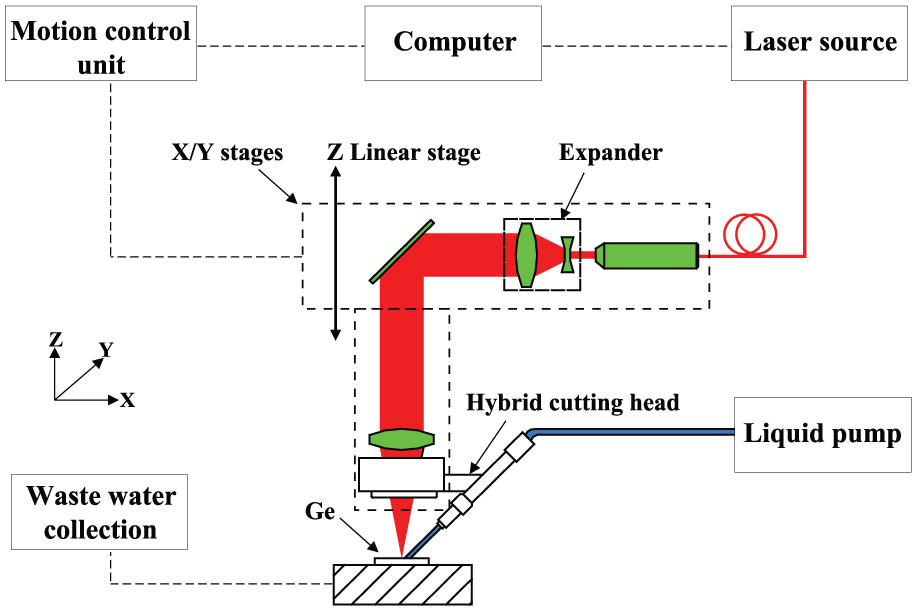
The experimental set-up is shown in Figure 1. While theoretically any type of laser may be used, the laser used in this work was a solid-state ytterbium (Yb) pulsed-fibre laser operating in Gaussian mode at 1080 nm wavelength with a 42-ns pulse duration. The laser was operated at a random polarization with a repetition frequency ranging from 20 to 100 kHz, and the laser pulse energy at 20 kHz frequency was up to 1.0 mJ. After going through a beam expander, the laser beam was directed to a Precitec fine cutting head with a focal length of 50 mm. Using this optical set-up, the laser spot diameter at 1/e2 of the peak intensity was 17.2 µm. An in-house designed liquid (water) pump was used which could generate a water pressure of up to 67 MPa. The pump was driven by pressurized air, and an accumulator was used to stabilize the water pressure. Finally, a waterjet was formed by a nozzle of 0.37-mm internal diameter.
Hybrid laser–waterjet machining system.
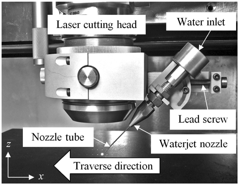
A laser–waterjet hybrid cutting head was designed in-house as shown in Figure 2. This cutting head allowed to precisely adjust the waterjet nozzle standoff distance (which is the distance from the nozzle exit to the target surface along the jet), the waterjet impact angle, and the offset distance between the laser and waterjet at the target surface. Due to space constraint, the impact angle in this apparatus could be adjusted from 35° to 65°. The cutting head could be moved by computer-controlled X–Y stages with the accuracy of movement at 1 µm over a 300-mm travel distance. Its vertical (Z-axis) movement which was required to adjust the laser focal plane position (fpp) was made manually with a linear stage at a resolution of 1 µm. During the cutting tests, the laser beam was moved with the cutting head along the workpiece surface and the waterjet was behind the laser beam to generate grooves.
Hybrid cutting head.
Experimental design
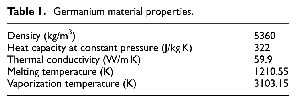
In this study, single-crystalline Ge wafers in <100> orientation with the thickness of 455 ± 30 µm and diameter of 25.4 mm were used as the test specimens, whose mechanical and physical properties are given in Table 1. In this laser-assisted waterjet technology, the laser is used to locally heat and soften work material, and the softened material is expelled by the high-pressure waterjet. Thus, all parameters that affect the heat source, heating process and jet impact process affect the material removal process, as shown in Figure 3. However, to reduce the experimental effort to a manageable size, only the easy-to-adjust parameters were considered, which included laser pulse energy, laser frequency, fpp that is the location of focal point in relation to the target surface, waterjet offset distance from the laser, water pressure, waterjet impact angle and traverse speed. The other parameters that were kept constant included the nozzle standoff distance of 0.5 mm and nozzle diameter of 0.37 mm during the experiment. It may be noted that the traverse speed (Vt) and laser frequency (f) may be represented by a non-dimensional factor of laser pulse overlap (PO), such that
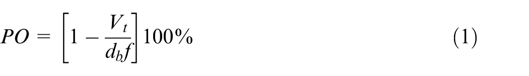
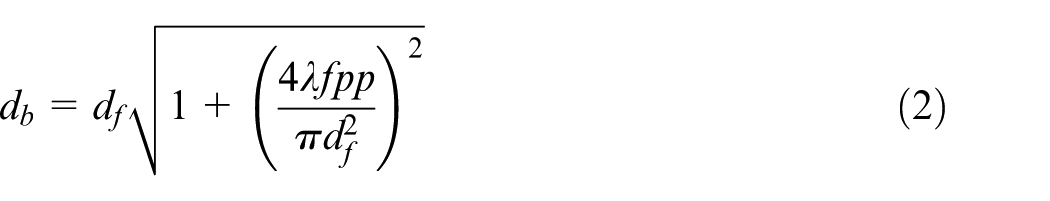
where db is the diameter of laser spot at the target surface and can be expressed as a function of focused laser beam diameter (df), fpp and laser wavelength (λ), that is
Germanium material properties.
Schematic of hybrid laser–waterjet machining.
The PO describes the percentage overlap between two successive pulses on the work surface. The fpp can be set as negative, zero and positive, where ‘negative’ or ‘positive’ are, respectively, for the focal plane being ‘below’ or ‘above’ the specimen surface. Positive fpp, however, is rarely used in machining applications, as it focuses the laser beam outside the work material. The PO in this experiment was varied by changing the traverse speed while the laser frequency was kept at 20 kHz for the maximum available pulse energy.
The selection of these six variables was made based on the available range of the relevant parameters from the experimental apparatus and a preliminary experimental study. To reduce the size of the experiment, two groups of tests each employing full-factorial design of experiment were carried out. In the first group, the laser PO, pulse energy, fpp and waterjet–laser offset distance, each at four levels, were tested under the constant waterjet impact angle (45°) and water pressure (6 MPa), as given in Table 2. The second group of tests focused on the effects of waterjet impact angle and water pressure. Four levels of each of the two parameters were included, and two levels for laser PO and pulse energy selected from the first group of tests, as shown in Table 3. In total, 320 tests were undertaken to produce grooves of approximately 1.4–2 mm in length, which should give sufficient data for sensible analyses.
Process parameters employed in the first set of tests.
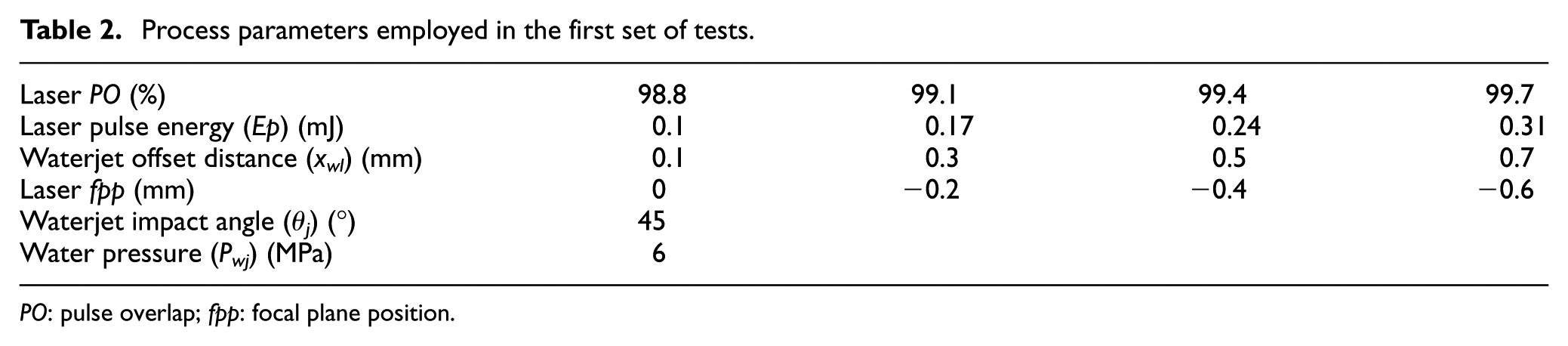
PO: pulse overlap; fpp: focal plane position.
Process parameters employed in the second set of tests.
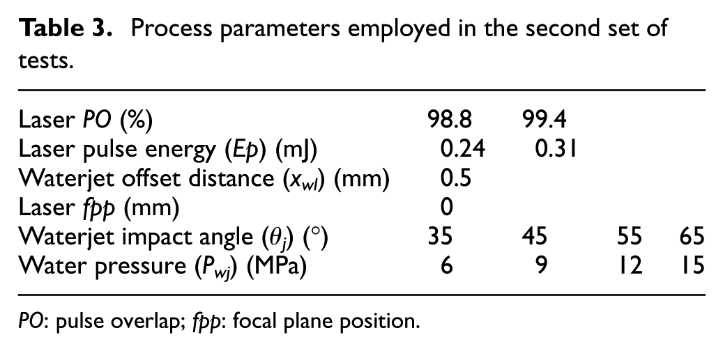
PO: pulse overlap; fpp: focal plane position.
After the experiment, the groove characteristics and quality in terms of top groove width, groove depth and HAZ width were measured using a three-dimensional (3D) laser microscope (Keyence Model VK-X200). For each groove, the microscope automatically measured 20 equally spaced cross sections over about 1 mm in the middle part of the groove for each groove geometrical feature, and the average was output as the reading. Figure 4 is a schematic showing the groove geometrical features and HAZ considered in this study. MRR was evaluated from the measured groove cross-sectional area and the traverse speed. In this study, the HAZ size is identified as the distance from the edge of the groove to where colour transition and/or thermal deformation of the material surface can be seen under the microscope. Some selected samples were examined under a Raman spectroscope about the Ge phase change following the machining, using a similar approach in Tangwarodomnukun et al. 21 A Renishaw inVia Raman microscope using a 25-mW, 514-nm wavelength argon-ion laser that was focused to a 1.5-µm diameter was used for this work.
Schematic of HAZ and groove geometry used in the study.
Relative location of laser and waterjet
The relative location of the waterjet and laser beam in this technology affects the interaction of laser and waterjet and how the waterjet impacts on the laser-softened site. A smaller distance or larger overlap between the waterjet and laser may cause more interference and hence reduce the laser beam quality and energy, while a too large distance between them may make it impossible for the waterjet to expel the laser-soften material at its softest state and take an effective cooling action. Thus, it is important to understand these effects and determine the appropriate or optimum distance between the laser and waterjet. Since a small standoff distance (0.5 mm) was used in this study, the effect of possible waterjet divergence as it flows downstream is neglected in the study of laser–waterjet interaction, based on the work in Nguyen et al. 23 Mathematically, the footprint of the waterjet on the Ge surface is an ellipse, which can be given by
where dj is the waterjet diameter and θj is the jet impact angle.
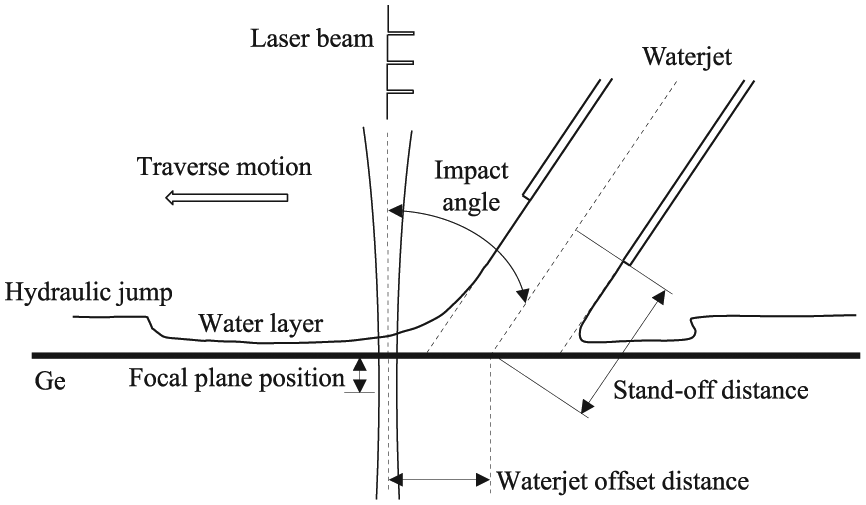
Figure 5 is a schematic of an idealized waterjet impacting a solid surface, where the water bouncing effect is ignored and the hydraulic jump zone is considered to be outside of the cutting zone. Thus, the water film thickness outside of the impact site can be approximated at 10% of the waterjet diameter.21,24 When the laser is positioned outside the waterjet footprint on the workpiece surface, the laser beam has to penetrate this thin film before striking the workpiece surface. By contrast, for a smaller waterjet offset distance, the overlap between waterjet and laser beam increases and the laser beam needs to penetrate a thicker bulk of water before arriving at the target, as shown in Figure 5. Thus, the thickness of water that the laser beam has to go through is related to the waterjet offset distance (xwl) by
Schematic of idealized water layer thickness and impact area.
According to equation (4), the waterjet offset distance that separates the laser beam from waterjet (i.e. the laser needs to penetrate only the thin water layer of 0.1dj thickness) is shown in Figure 6(a), from which it can be noticed that a larger offset distance is required to separate the waterjet from the laser beam as the waterjet impact angle increases.
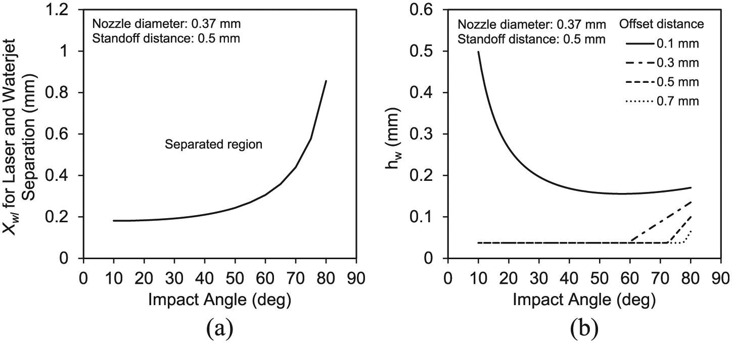
Effects of waterjet impact angle on: (a) the offset distance (xwl) for separating laser beam and waterjet and (b) the water film thickness (hw) for laser to penetrate.
Figure 6(b) illustrates the relationship between the waterjet impact angle and the water film thickness that the laser needs to penetrate. It can be seen that the waterjet offset distance of 0.3 mm or more will separate the laser beam from the waterjet on Ge surface for an impact angle less than 60°. However, it is noted that although the laser and waterjet are separated on the target surface, the transition groove formed during machining will create a new condition where the waterjet becomes interfering with the laser beam if the offset distance is small and/or the waterjet impact angle is large. Thus, a larger offset distance than the calculated one may be used in practice.
It should be noted that although the thin water film thickness outside the jet impact area is assumed to be 10% of the jet diameter, it in fact varies depending on many factors. According to Watson’s 25 study and other experimental findings,26,27 there exists a location, r0, from the stagnation point in the jet impact site, where the water film thickness reduces to a minimum. It appears that the offset distances used in this study are all less than this critical distance r0, and an increase in the waterjet offset distance from 0.1 to 0.7 mm is expected to result in a decrease in the water film thickness that the laser needs to penetrate. Teamah et al. 28 and Kate et al. 29 found from the experimental measurements that when the waterjet impact angle increases, the water layer thickness increases correspondingly both before and after the hydraulic jump. It was further observed by Teamah et al. 28 that within a small distance from the impact site, an increase in the water flow rate due to water pressure increase (which increases the Reynolds number as well) increases the water layer thickness surrounding the jet. This is supported by other studies.26,27,30,31 It has also been reported 32 that the surface condition of the target affects the hydrodynamic behaviour of the water layer from a jet impact. Thus, once a groove is formed during the ablation process, the change in the surface condition may result in water splashing which can cause optical reflection and deflection and reduce the quality and intensity of the laser beam.
From the above analysis, it has become apparent that to take into account all these factors is difficult and some simplifications, such as that depicted in Figure 5, may need to be made to study the laser–waterjet interaction in this machining process. Furthermore, it has been shown that a water layer has to be penetrated by the laser beam in the process and its thickness is mainly dependent on the waterjet offset distance and impact angle, although other conditions have been reported to affect this quantity. As a result, some interference of the water layer to the laser beam is inevitable. It has been found from an experimental study 21 that a good compromise for the requirements to minimize this interference and maximize the jet impact and cooling effect is to set up the laser beam such that it intersects at the edge of the waterjet on the specimen surface. This appears to support the aforementioned analysis and has been used in assisting the experimental design in this study.
Micro-grooving performance
Comparison between laser dry and hybrid ablation
Laser cutting of Ge without applying a waterjet was performed using the four levels of laser fpp, PO and pulse energy given in Table 2, and the results were compared with the corresponding data from the hybrid machining. In many cases of laser dry cutting, it has been noted that grooves could not be properly formed. Instead, as a consequence of melt resolidification, humps (or ripples) were observed along the laser path (irradiated area) on the target surface. Material depositions could also be found in the surrounding area, as shown in Figure 7(a) and (b). Large HAZs of more than 70 µm on each side of the grooves were found on the Ge surfaces.
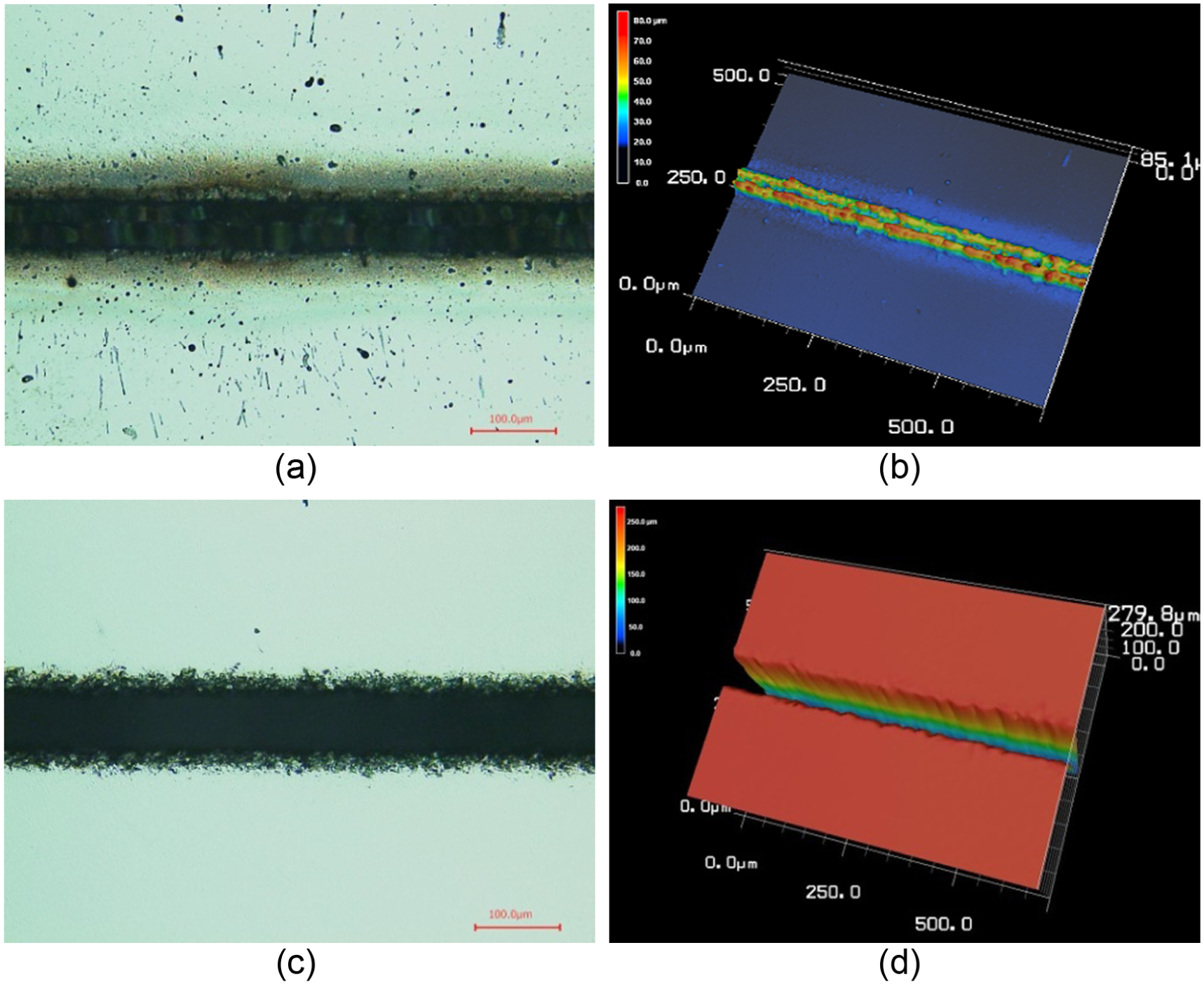
Ge surface profiles after machining when fpp = 0, PO = 99.1% and Ep = 0.31 mJ: (a) and (b) top and 3D view of surface after laser dry machining; (c) and (d) top and 3D view of surface after laser–waterjet machining when θj = 45°, Pwj = 6 MPa and xwl = 0.5 mm.
The top and 3D views of a groove produced by the hybrid process are illustrated in Figure 7(c) and (d), respectively, confirming that good quality grooves could indeed be produced by this hybrid laser–waterjet technology. No debris or depositions were found on the surfaces. The pile-ups that are normally observed at around the cut edges in laser dry cutting were minimized to a negligible level. The process parameters can be appropriately selected to reasonably control the groove geometry and, for the grooves produced, the groove depth is up to 300 µm, while the groove widths on the top surface are within 100 µm. The HAZ size on each side of the groove can be controlled to within 20 µm. Figure 8(a) and (b) shows a comparison of the HAZ width between laser dry cutting and hybrid cutting under corresponding conditions, which amply demonstrates the advantage of the hybrid technology.
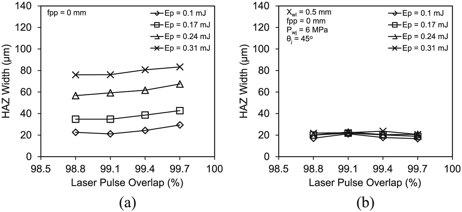
Comparison of HAZ width between (a) laser dry cutting and (b) hybrid cutting process (fpp: focal plane position, xwl: waterjet offset distance, qj: waterjet impact angle, PO: pulse overlap, Pwj: water pressure, and Ep: laser pulse energy).
The Raman spectra of both non-ablated and ablated Ge surfaces have been found to fit with Lorentz distribution, as shown in Figure 9. Peak shift was hardly discernible, while the difference in the full width at a half maximum (FWHM) between the non-ablated and ablated surfaces is within 2 ± 0.5 cm−1. As a result, the crystallinity of the material is retained after machining.
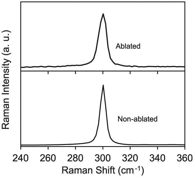
Raman spectra of non-ablated and ablated (focal plane position fpp = 0, pulse overlap PO = 99.4%, laser pulse energy Ep = 0.17 mJ, waterjet impact angle qj = 45°, water pressure Pwj = 6 MPa and waterjet offset distance xwl = 0.5 mm) crystalline Ge surfaces.
Figure 10 shows a comparison of the machined grooves and the surrounding area topologies between laser dry and the hybrid processes, which amply demonstrates the advantages of using the hybrid technology. For this particular case, laser dry machining was unable to generate any acceptable groove, but hump-ups as shown in Figure 11(a). By contrast, good grooves have been created by the hybrid process under the corresponding process parameters, as shown in Figures 10 and 11(b).
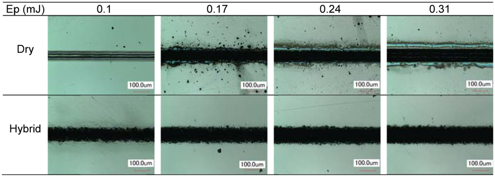
Top views of machined Ge surfaces (pulse overlap PO = 99.1% and focal plane position fpp = −0.4 mm; waterjet impact angle qj = 45°, water pressure Pwj = 6 MPa and offset distance xwl = 0.5 mm for hybrid machining).
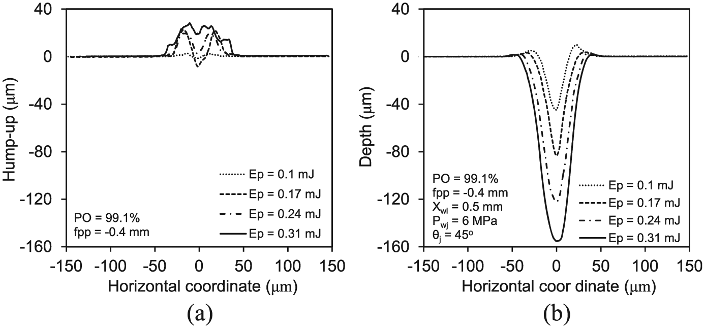
Ge surface profiles after machining: (a) cross-sectional profile after laser dry irradiation and (b) cross-sectional profile after laser–waterjet machining (fpp: focal plane position, xwl: waterjet offset distance, qj: waterjet impact angle, PO: pulse overlap, Pwj: water pressure, and Ep: laser pulse energy).
Effects of process parameters on the top groove width
To investigate which parameters significantly affect the top groove width, an analysis of variance (ANOVA) was conducted. Based on the ANOVA results, all process parameters have a p value of <0.05, indicating that they all significantly affect the groove width at a 95% confidence interval. The highest F-value is on the laser pulse energy so that it affects groove width most significantly.
The effect of fpp on the top groove width is plotted in Figure 12(a). For smaller laser pulse energies, such as 0.1 and 0.17 mJ, the groove width appears to increase when fpp increases from −0.6 to 0 mm; however, the groove width shows a decreasing trend with fpp at higher laser pulse energies. This complex trend may be explained as follows. The laser pulse energy is in a Gaussian distribution with the maximum value at the beam centre. Thus, the size of the target that is heated and softened enough for the waterjet to remove at a selected water pressure is dependent on the laser energy distribution and intensity. When the pulse energy is low and spreads over a large spot size on the target surface, for example, at fpp = −0.6 mm, the heated area on the target that is sufficiently softened for the waterjet to remove is expected to be small, so is the top groove width. This situation may be further manifested by the expected loss of laser energy after passing through a thin water layer. As the focal plane is moved close to the target surface so that the laser spot size on the surface becomes small, the laser intensity is expected to increase, along with the laser-softened size on the target. As a result, an increase in fpp at lower laser pulse energies increases the top groove width. In contrast, for higher pulse energies, such as 0.24 and 0.31 mJ, the laser is able to soften a larger area on the specimen surface even with a larger spot size at a larger negative fpp than a smaller spot size at a smaller or zero fpp. The spreading of laser energy on a larger spot size appears to still yield a larger area on the target that is sufficiently softened for removal by the waterjet. As a result, the groove becomes narrower as the fpp increases under higher laser energies.
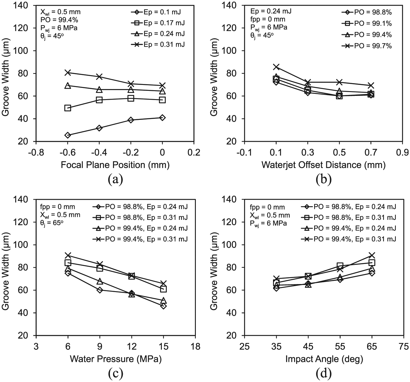
Effects of parameters on groove width: (a) focal plane position, (b) waterjet offset distance, (c) water pressure and (d) impact angle (fpp: focal plane position, xwl: waterjet offset distance, qj: waterjet impact angle, PO: pulse overlap, Pwj: water pressure, and Ep: laser pulse energy).
Figure 12(a) also displays the effects of laser pulse energy on groove width, where the groove width on the top surface shows an increasing trend with the pulse energy. It is apparent that a higher input laser energy is expected to generate a larger laser-heated area, so that more material can be softened and subsequently removed by waterjet to make a wider groove.
The effect of waterjet offset distance on the top groove width is plotted in Figure 12(b), where an increase in the offset distance is associated with a decrease in groove width on the top surface. It follows that as the jet is further away from the laser, the jet pressure applied to the laser-softened area is reduced or the jet may impact after the laser heating. In the former case (typically at the offset distance of 0.1–0.3 mm in which the laser still intersects with the waterjet), only the material in a more softened status can be expelled by the part of jet at lower pressure, but in the latter case, the temperature of the heated area may be reduced, so the area that is soft enough for the waterjet to remove is reduced. As a result, a narrow groove is produced.
It can be noted in Figure 12(b) that the groove width on the top surface shows an increasing trend with laser PO. It is expected that more energy is brought into a given position on the specimen by a larger PO, which should increase the heated area that is soft enough for the waterjet to remove and hence a wider groove.
The effect of the water pressure on the top groove width is indicated in Figure 12(c), where the top groove width shows a decreasing trend with the water pressure. This may be attributed to the following facts. It is expected that a higher water pressure will yield higher impact force to remove less softened material and generate a wider groove. However, a higher pressure and velocity jet increases the Reynolds number and the heat transfer coefficient, so that its cooling effect is increased to reduce the temperature of the material. Furthermore, increasing the water pressure is expected to increase the jet turbulence and the interference of the jet to the laser beam and may also increase the water film thickness that the laser has to go through. As a result, it tends to reduce the groove width, although this effect is expected to be small. Depending on the relative magnitudes of the effects of the increased impact force from a higher pressure jet that intends to produce a wider groove and the tendency to reduce the groove width due to the increased cooling action and waterjet interference to the laser, the groove width may be increased or decreased. Clearly, the effect of the increased impact force in this case has not traded off the cooling effect, so that the top groove width shows a decreasing trend with the water pressure.
Figure 12(d) displays how waterjet impact angle affects the groove width, where the increase in the impact angle results in the top groove width to increase. Since the waterjet is placed offset behind the laser while inclining backward with reference to the laser beam, if the impact angle increases, the thickness of the water layer that the laser has to go through is expected to increase, which should cause more interference to the laser and less heated area that is soft enough for removal by the waterjet. Furthermore, the increase in the impact angle increases the shear force caused by the waterjet along the work surface. Thus, the groove width should exhibit an increasing trend with respect to the waterjet impact angle. At a 0.5-mm offset distance shown in Figure 12(d), the waterjet and laser are separated at the specimen surface for an impact angle of less than about 70° (Figure 6(a)). Thus, increasing the jet impact angle within the studied range moves the jet impact site close to where the material is irradiated by the laser at higher temperature. As a result, a wider groove is produced.
Effects of process parameters on groove depth
According to the ANOVA conducted, all the six process variables significantly affect the groove depth at a 95% confidence interval. It also shows that the pulse energy has the highest F value and hence has the most influence on the groove depth.
Figure 13(a) indicates that an increase in fpp from −0.6 mm to 0 is associated with an increase in the groove depth. As can be observed from Figure 13, the maximum groove depth is less than 300 µm. Thus, when a larger negative fpp, such as −0.6 or −0.4 mm, is used, the laser is focused somewhere much below the cutting front (i.e. the transition surface changing from the work surface to the final groove bottom surface), so that it provides a lower energy density on the cutting front for a shallower cut to be formed by the waterjet. Unfortunately, the groove depth did not go beyond the focal plane to take the advantage of the heating at the laser focal point. By contrast, the opposite applies when a less negative or zero fpp is used, where the laser can provide a higher energy density in the vicinity of the cutting front for a deeper cut to be formed by the waterjet.
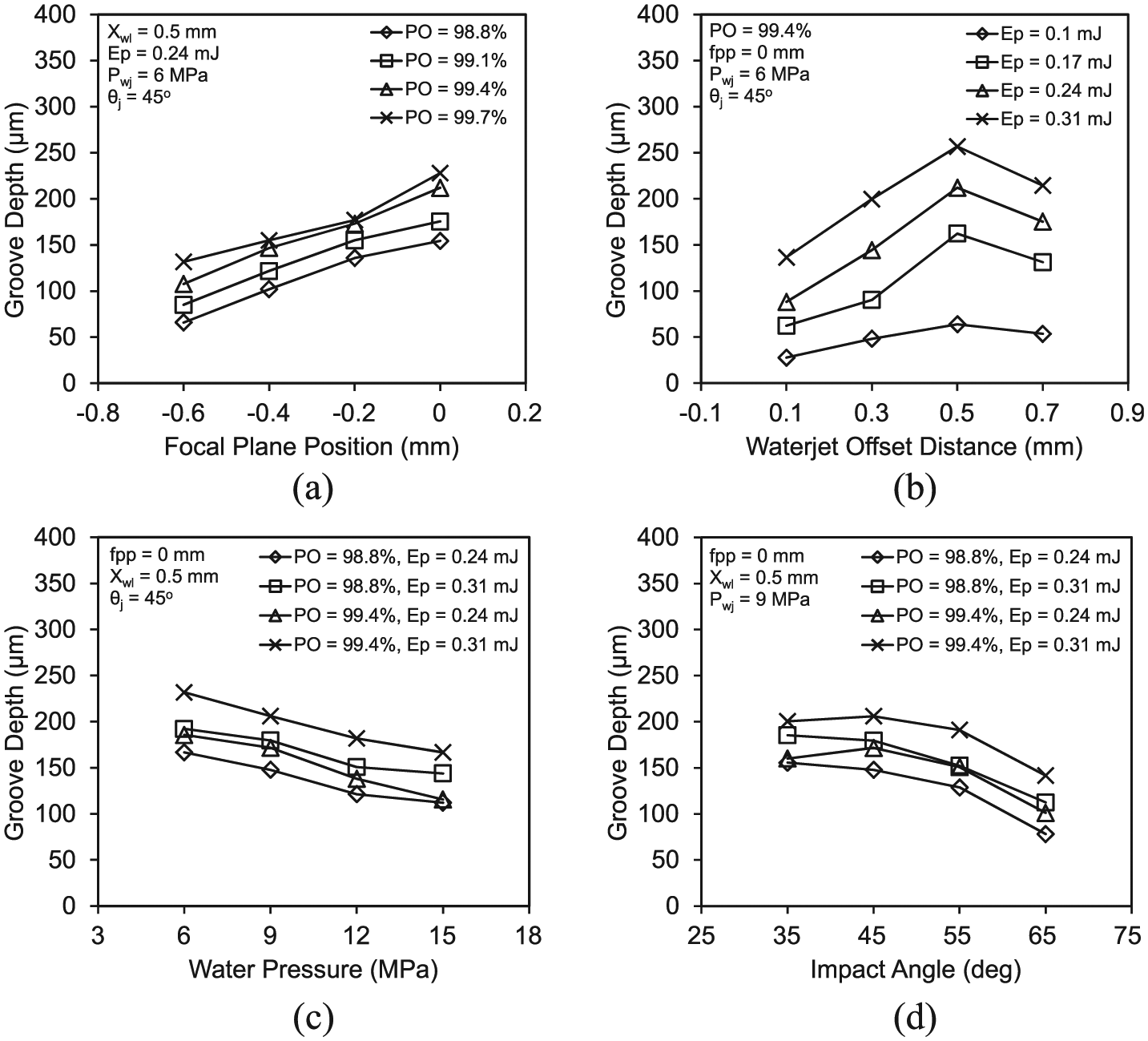
Effects of parameters on groove depth: (a) focal plane position, (b) waterjet offset distance, (c) water pressure and (d) impact angle (fpp: focal plane position, xwl: waterjet offset distance, qj: waterjet impact angle, PO: pulse overlap, Pwj: water pressure, and Ep: laser pulse energy).
Figure 13(a) also illustrates the effect of laser PO on the groove depth, where the groove depth shows an increasing trend with the laser PO. It follows that more energy is brought into a given part on the cutting front by a higher laser PO, so that the heated area that is soft enough for the waterjet to ablate is increased, and the groove depth as well as width are increased.
Figure 13(b) shows that the groove depth initially increases with the waterjet offset distance to a peak value at the offset distance of around 0.5 mm, but then decreases when the offset distance is increased further. As shown in Figure 5, the thickness of water that the laser has to go through decreases when the offset distance increases so that the water interference to the laser decreases until the laser and waterjet are separated. At a 45° of the impact angle shown in Figure 13(b), the distance to separate the waterjet and laser at the work surface is about 0.3 mm, but with the increase in the grooving depth, the distance to separate the laser and waterjet in the cutting front is increased depending on the depth of cut; for the conditions given in Figure 13(b), it is about 0.5 mm. Thus, the effect of waterjet on the laser beam is reduced as the laser–waterjet offset distance is increased to about 0.5 mm while the waterjet can maintain a good impact within this distance. As a result, a deeper groove is produced. However, as the offset distance further increases to beyond 0.5 mm, the waterjet cannot immediately impact the laser-heated cutting front, but somewhere after the laser irradiation, so that the target temperature at the jet impact site decreases as the offset distance increases, so does the groove depth.
Figure 13(b) also indicates the effects of laser pulse energy on the groove depth, where the groove depth shows an increasing trend with the laser pulse energy. It is apparent that more input energy is expected to result in a larger heated work element that is soft enough for the waterjet to remove, so that the groove depth as well as width are increased.
The effects of the water pressure on the groove depth are displayed in Figure 13(c), where the groove depth shows a decreasing trend with the water pressure. This may be explained similarly to the relationship between the water pressure and top groove width, that is, the ability of an increased water pressure to remove less laser-softened specimen did not trade-off the increased cooling effect on laser heating and the increased waterjet turbulence effect on the laser quality and energy transfer as the water pressure increases, so that the increase in the water pressure corresponds to the decrease in the groove depth within the range tested.
Figure 13(d) illustrates how the impact angle of the waterjet affects the groove depth, where the groove depth shows a decreasing trend with the impact angle within the range tested. As shown in Figure 6(a), at 0.5 mm of offset distance, the waterjet is separated from the laser beam on the work surface at an impact angle of less than 70°. When the impact angle increases, the laser beam has to penetrate a thicker water film, thus less laser energy with reduced beam quality is expected to strike on the target. Furthermore, the impact force in the direction perpendicular to the target surface decreases when the impact angle increases. The overall effect appears to have caused the groove depth to decrease with the waterjet impact angle.
Effects of process parameters on MRR
According to the ANOVA performed, all the six process parameters have a significant effect on the MRR at a 95% confidence interval. The highest F value is on the laser pulse energy, thus the input laser energy has the most profound effect on MRR. In addition, the fpp has the lowest F value and hence the least significant effect, mostly because the data have a complex trend as shown in Figure 14(a).
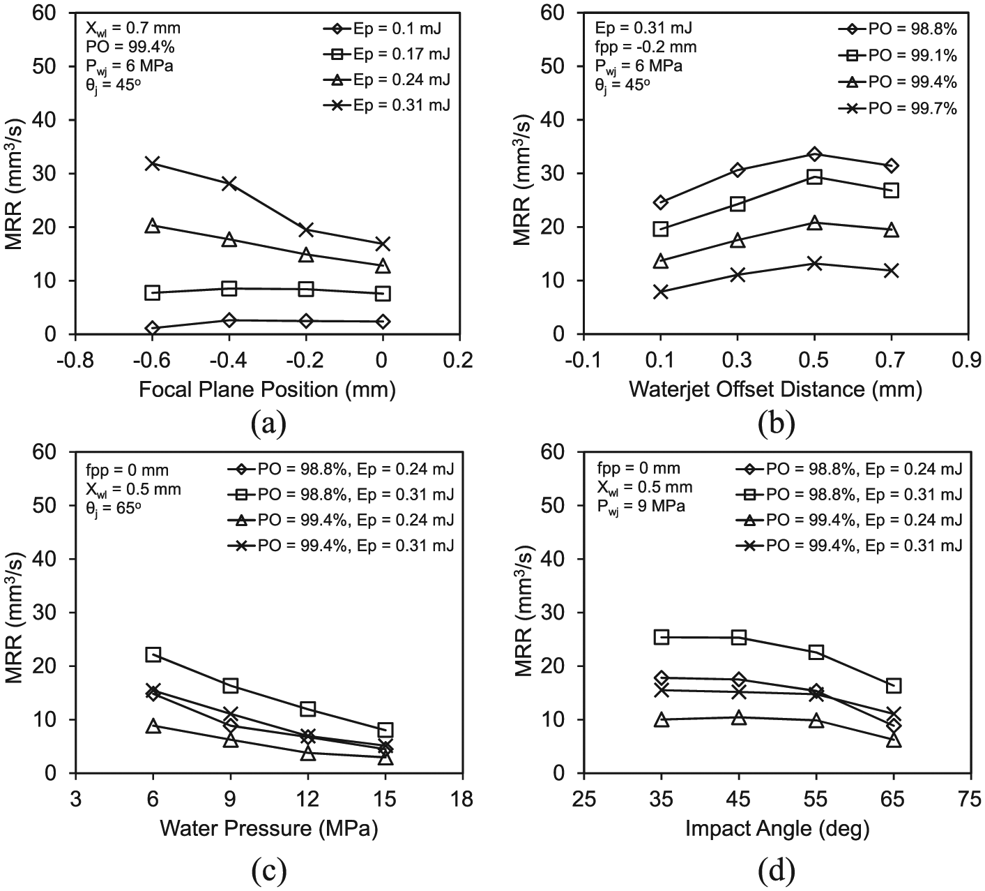
Effects of parameters on MRR: (a) focal plane position, (b) waterjet offset distance, (c) water pressure and (d) impact angle (fpp: focal plane position, xwl: waterjet offset distance, qj: waterjet impact angle, PO: pulse overlap, Pwj: water pressure, and Ep: laser pulse energy).
Figure 14(a) indicates the effect of fpp on MRR. At low pulse energies, such as 0.1 or 0.17 mJ, the effect of fpp on MRR is very small, as at this energy level the MRR is already small and any effect on the MRR is expected to be marginal. As the pulse energy is increased, the effect of fpp appears to increase and an increase in fpp causes the MRR to decrease. It is noted that the laser PO is defined at the work surface, so that a change in fpp is associated with a change in the laser beam size on the work surface, and subsequently a change in the traverse speed when the pulse repetition rate is constant. Thus, the effect of fpp on MRR may be attributed to its effect on the groove cross-sectional area and the change in traverse speed. When fpp increases from −0.6 to 0 mm, the groove sectional area is expected to increase considering the relatively small change in groove width as plotted in Figure 12(a) and a substantial groove depth increase as plotted in Figure 13(a). However, as the fpp increases, the laser spot size on the specimen surface is reduced so that to maintain the same PO, the traverse speed has to be reduced. As the MRR is the product of groove cross-sectional area and traverse speed, the MRR may be increased or decreased with fpp. From Figure 14(a), it is apparent that the increase in the groove cross-sectional area due to fpp increase has not traded off the effect of decreasing the traverse speed at higher pulse energies, so that the overall MRR decreases as the fpp increases.
Figure 14(a) also indicates the effects of laser pulse energy on MRR, where the MRR increases consistently when the laser pulse energy increases. This is anticipated as a higher energy input is expected to heat more material to be soft enough for the waterjet to remove, and the study has correctly shown this effect.
Figure 14(b) indicates the effects of waterjet–laser offset distance on the MRR. It can be noted that the MRR increases initially as the offset distance increases until around 0.5 mm, and then decreases when the offset distance is increased further. This may be attributed to the same facts as discussed earlier for the groove depth and shown in Figure 13(b). Since the top groove width varies marginally with a change in the waterjet offset distance (Figure 12(b)), but the groove depth changes significantly, for a given traverse speed, the MRR should show a similar trend as the groove depth when the offset distance changes.
Shown in Figure 14(b) are also the effects of laser PO on the MRR, where the MRR decreases as the PO increases. While a larger laser PO is expected to provide more laser energy on a given area on the target and, hence, remove more material, such an increase is in the cost of the traverse speed that has to be decreased at a constant laser pulse repetition rate. From Figure 14(b), it is apparent that the effect of the increased groove cross-sectional area has not traded off the effect of reduced traverse speed on the MRR, thus the overall MRR decreases as the PO increases.
Figure 14(c) indicates the effects of water pressure on MRR, where the MRR shows a decreasing trend with water pressure. Since both the groove depth and width decrease when the water pressure is increased, as discussed earlier, the MRR is expected to decrease.
Figure 14(d) indicates that increasing the waterjet impact angle decreases the MRR. This is mainly a result of the decrease in the depth of cut and hence the groove cross-sectional area, so can be explained similarly to the effect on groove depth. Since the waterjet impact angle when varying from 35° to 65° causes a relatively small increase (within 30%) in the top groove width as shown in Figure 12(d), while its effect on the groove depth is substantial (decreasing the groove depth by up to nearly 50%) as shown in Figure 13(d), it follows that the MRR shows a decreasing trend with the jet impact angle.
Effects of process parameters on HAZ size
According to the ANOVA results, the parameters that significantly affect the HAZ size include waterjet offset distance, laser fpp, waterjet impact angle and water pressure. Other parameters, that is, the laser PO and pulse energy, show a very small effect on the HAZ. In addition, the waterjet offset distance has the most significant effect on HAZ size based on an F test.
Figure 15(a) shows the effect of fpp, on the HAZ. It can be observed that an increase in fpp from −0.6 to 0 mm causes a decrease in the HAZ size. When the laser is focused somewhere below the work surface at a negative fpp, the diameter of laser spot at the target surface is greater than that at the focal plane, which is expected to heat a larger area on the target surface and cause a larger HAZ after the waterjet removes the softened material. Figure 15(a) also indicates that the change in the laser PO does not cause a significant variation of the HAZ. While a larger laser PO increases the energy input into the work surface, and hence the material that can be removed by the waterjet for an increased groove cross-sectional area, as discussed earlier, but what remains on the workpiece may have the same temperature contour and the same HAZ size.
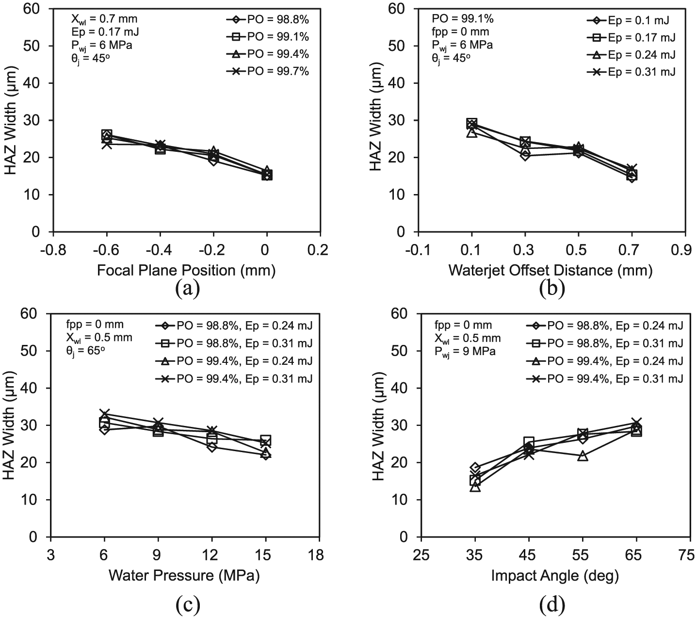
Effects of parameters on HAZ size: (a) focal plane position, (b) waterjet offset distance, (c) water pressure and (d) impact angle (fpp: focal plane position, xwl: waterjet offset distance, qj: waterjet impact angle, PO: pulse overlap, Pwj: water pressure, and Ep: laser pulse energy).
Figure 15(b) shows that a smaller HAZ size can be yielded when the waterjet–laser offset distance is increased. This is mainly attributed to the waterjet cooling effect. At the 45° impact angle shown in Figure 15(b), the increase in waterjet–laser offset distance from 0.1 to 0.7 mm gives more time for the jet to interact and cool the laser-heated area and, hence, a reduced HAZ size. Figure 15(b) also indicates that the change in laser pulse energy affects the HAZ size marginally. An increase in the pulse energy provides more laser energy into the workpiece, which is anticipated to cause an increase in the volume of the material that is above the temperature threshold for removal and an increase in the MRR; however, under a given impact condition of the waterjet, the material remains on the workpiece should have the same temperature contour when the laser pulse energy is varied, so that the change in the HAZ is small.
The effects of the water pressure on the HAZ are plotted in Figure 15(c), where the HAZ size shows a decreasing trend with the water pressure. It follows that less softened material can be expelled by a high water pressure. Meanwhile, a better cooling effect can be introduced by this increased water pressure. As a result, the material left on the workpiece is expected to have a lower temperature contour and hence a smaller HAZ.
Figure 15(d) illustrates how the impact angle of the waterjet affects the HAZ size, where the HAZ size on the top surface shows an increasing trend with the impact angle. As discussed in Tangwarodomnukun et al., 22 the expelling force at the jet impact angle of around 30–40° can remove the laser-heated material at the lowest temperature, so did this study as shown in Figure 14(d), so that the unremoved material is expected to have a lower temperature contour and hence smaller HAZ size. At the other impact angles, HAZ size is increased. The finding shown in Figure 15(d) appears to follow this trend.
Conclusion
A study of the cutting performance in micro-grooving of Ge wafers employing a laser-assisted waterjet technology has been presented. It has been shown that this technology is superior to the traditional laser cutting technology in damage-free fabrication of micro-structures on the selected material. The Raman spectrum tests did not reveal any crystalline change to the specimens by the machining process, while the HAZ on each side of the groove can be controlled to within 20 µm. It has been shown that HAZ size may be reduced by selecting larger laser–waterjet offset distance or higher water pressure, although it is at the cost of decreased groove depth and MRR. The effects of the process parameters on the grooving performance indicators have been discussed and are summarized below:
An increase in laser pulse energy in the range tested yields a wider and deeper groove with an increased MRR, while its effect on HAZ size is not significant. Thus, a larger laser pulse energy may be employed, considering the requirement of groove width.
Laser PO has a similar effect on the cutting performance to the laser pulse energy. From a productivity point of view, a smaller PO within the range tested (corresponding to a higher traverse speed) is recommended together with a higher laser pulse energy.
Groove depth and MRR increase initially as the waterjet–laser offset distance increases, but then decrease as the offset distance is increased further, while the groove width and HAZ size show a slight decreasing trend with waterjet offset distance.
The increase in waterjet impact angle causes an increase in the top groove width and HAZ size, but decreases the groove depth and MRR. Therefore, a smaller jet impact angle may be employed for a deeper and narrower groove with a smaller HAZ.
An increase in the position of focal plane fpp within the tested range of −0.6 to 0 mm decreases the HAZ size and increases the groove depth, while its effects on groove width and MRR depend on the input laser pulse energy. From this study, zero fpp is recommended to provide a smaller HAZ and groove width and a larger groove depth.
A higher water pressure results in a narrower and shallower groove with a lower MRR and slightly reduced HAZ size. From this study, a compromised water pressure in the range of 6–12 MPa may be considered.
A computational study is being conducted to understand the material removal mechanism. It is hoped to report on this work shortly.
Footnotes
Declaration of conflicting interests
The author(s) declared no potential conflicts of interest with respect to the research, authorship and/or publication of this article.
Funding
The author(s) disclosed receipt of the following financial support for the research, authorship, and/or publication of this article: This project was supported by the Australian Research Council (ARC) under the Discovery-Projects scheme and the National Natural Science Foundation of China (project ID 51375273).