
Abstract
High aspect ratio micro-grooves are critical structures in the micro-electromechanical system. However, problems like rapid tool wear, low processing efficiency, and inferior machined quality in micro-milling of high aspect ratio micro-grooves by length–diameter ratio tools are particularly significant. In this work, a combined micro-milling method based on water-free alcohol as the cutting fluid and laser deburring is proposed to investigate the high aspect ratio micro-groove generation of oxygen-free high-conductivity copper TU1. Parametric experiments and high aspect ratio micro-groove experiments were conducted to investigate the surface quality, cutting forces, and tool wear. The water-free alcohol was employed to improve the tool life and machined surface quality. In the case of the oxygen-free high-conductivity copper TU1 material, a satisfactory high aspect ratio micro-groove (groove-width = 0.2 μm and aspect ratio = 2.5) with a nanoscale surface roughness (Ra = 68 nm) was obtained under the preferred machining conditions. Furthermore, the deburring process of the high aspect ratio micro-groove by the laser technology was conducted to achieve ideal machined quality of the top surfaces.
Introduction
With the increasing application of micro-machinery, thin and tall ribs are required for many parts to reduce their weights without sacrificing the stiffness and strength. This results in constantly expanding demand of micro-grooves with high aspect ratio (HAR). 1 The machined quality of high precision micro-grooves is responsible for the life length of the micro-components. However, the fabrication of such micro-grooves is highly tricky due to the small dimensions, high machined precision, and superior surface quality.
In recent years, with the emergence of difficult-to-cut materials in micro-machinery, various machining technologies like non-traditional machining,2–4 high-speed grinding, 5 and micro-milling 6 have been gradually applied to fabricate the HAR micro-grooves with strict machined quality requirements. Uno et al. 7 conducted an experimental study of electrical discharge machining (EDM) forming system of narrow slots using a rotating disk electrode and found that the processing time required of EDM with the rotating disk electrode was shorter than that with a rectangular electrode. In order to solve the problem of poor rigidity of the cathode structures, Zhao et al. 8 carried out a systematical optimization technology research of the EDM processing and cathode structures, and then they fabricated a deep-narrow slot structure of titanium alloy with an aspect ratio of 9 using the optimized electrolytic conditions. Aiming at improving the electrolytic speed of the machining gap, an electrochemical machining method for low-frequency tool vibration was proposed. 9 The maximum deviation of the slot depth and width was estimated to be 0.03 and 0.08 mm, respectively. However, as the depth increased, the electrodes were very easy to wear, and discharge chips produced by EDM were difficult to expel, which further resulted in lower processing efficiency and inferior surface quality.
LIGA (Lithographie, Galvanoformung and Abformung)/UV-LIGA has many advantages in fabricating three-dimensional (3D) structure devices with larger aspect ratio and steeper side walls. United States generated some HAR slow-wave structures (220 GHz) by UV-LIGA, such as S-shaped cavity traveling wave tube structures with the width and the depth of 100 μm and 1 mm, respectively. 10 Pan et al. 11 fabricated slow-wave structures of 0.22 and 0.34 THz by UV-LIGA. The width of these micro-grooves was less than 0.2 mm, and the aspect ratio was greater than 4. However, the problems of processing accuracy and quality were not reported. Xi et al. 12 carried out some research on the back-wave oscillator (BWO) with planar slow-wave structure using UV-LIGA technology. The width and aspect ratio of the slit structure were 58 μm and close to 3, respectively. The results show that the processing error was less than 0.003 mm and the output power of the BWO has been significantly improved. With the new requirements for micro-productions, high-speed and high-efficiency grinding have provided a new way for fine-groove machining. 13 Bai et al. 14 manufactured some deep-narrow straight-grooves on SUS321 stainless steel workpiece by monolayer electroplated cubic boron nitride (CBN) grinding wheel. The width achieved was 2 mm, and the depth was 5, 8, and 12 mm, respectively. Despite the above research, some achievements have been made in this respect. To synthesize the above research results, some achievements have been made in the precision fabrication of HAR micro-grooves. However, the disadvantages of these technologies also have limited the broader applications to a certain extent. For LIGA/UV-LIGA, the most prominent shortcomings were the relatively more complex machining process, higher cost, longer machining cycle, and so on. Meanwhile, severe wear and blockage of grinding wheels as well as abrasive particles shedding usually caused the premature failure of wheels. 15
Micro-milling technology is another effective and suitable method that can be applied to machine the micro-HAR grooves due to its outstanding advantages of micro-milling technology in terms of high efficiency, high flexibility, high precision, and low cost.16,17 For instance, micro-grooves with the width of 0.253 mm and depth of 1.016 mm in tungsten carbide workpiece were generated by employing a polycrystalline diamond (PCD) micro-cutter under the optimized micro-milling technological conditions. 18 The peak-to-valley surface roughness achieved was measured to be less than 40 nm. A new method for machining deep-grooves of hardened die steel materials using variable pitch cutters with a directional feed thin-wall support was proposed. 19 Results showed that the developed method could effectively suppress chatter vibration, but this method was mainly effective for the macro-milling.
Furthermore, oxygen-free coppers are the primary materials of the HAR slow-wave structures because of the excellent properties concerning high conductivity, outstanding processing performance, and low-temperature performance. The chips generated in the cutting process are easy to soften under the action of the cutting temperature due to their large plastic and low phase transition temperature. 20 Micro-pillar arrays of polycrystalline oxygen-free copper with a HAR (the pillar dimension was 12.8 μm × 15.8 μm × 28.2 μm) were generated by putting forward a novel cutting strategy with a reduced cross-feed in the non-coolant condition. The burrs at the groove edges were found because of material pile-up and deformation, but a reduced burr size and improved surface roughness were obtained by utilizing the proposed method, and the cutting performance of micro-tools was also significantly improved. 21
For the micro-milling, the prominent problems mainly include rapid tool wear, inferior surface quality, heavy micro-burrs, and so on. The processing quality of parts directly affects the causative performance of micro-components in practical application. Although many researchers have been devoted in investigating the micro-milling process of micro-structures from different perspectives in recent years, there are still many critical technical problems yet to be addressed. Therefore, it is highly desirable to conduct in-depth research to develop the application potential of micro-milling technology, particularly for the HAR micro-grooves with a width of 0.2 μm and an aspect ratio of more than 2.
In this work, micro-milling parametric experiments and HAR micro-groove experiments of the oxygen-free high-conductivity copper TU1 (OFHC-TU1) material were conducted to investigate surface quality, cutting forces, and tool wear in succession. The effects of cutting parameters (including feed per tooth and depth of cut) on machined surface quality (surface roughness and burr formation) were investigated in detail first. Then, the HAR micro-groove experiments were conducted to focus on the analysis of machined surface quality, cutting forces, and tool wear. Besides, an investigation of the laser deburring process was performed after the micro-milling experiments to achieve superior top surfaces.
Experimental setup and methodology
Experimental preparation
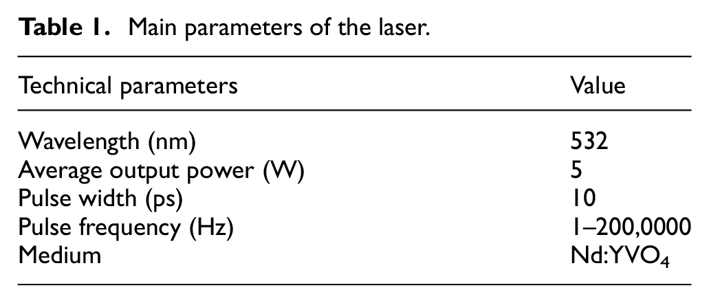
Full-immersion micro-groove experiments were conducted on a multi-function precision micro-cutting machine (Figure 1). The maximum rotation speed is 100,000 r/min, and the spindle rotation precision is less than 1 μm. The microscope system aims to assist in the tool setting and on-line monitoring of the whole micro-milling process. A dynamometer (Kistler® 9256C1) is mounted on the X–Y stage to measure the cutting forces. The minimum force threshold and the maximum sampling frequency are 0.002 N and 30 kHz, respectively. For the deburring process, a picosecond laser system (Edgewave, Nd:YVO4) is utilized in this work, and the schematic of the laser system is shown in Figure 2. The main parameters of the laser system are given in Table 1.
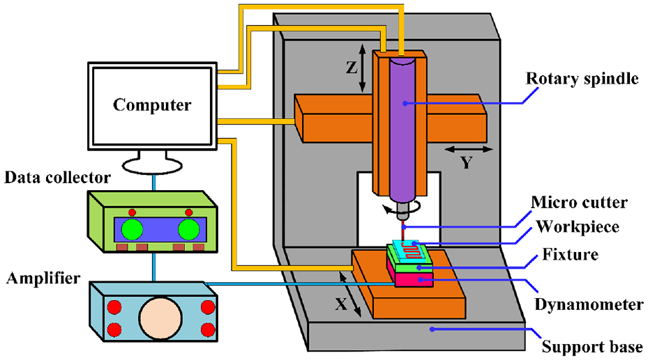
Schematic diagram of the experimental system.
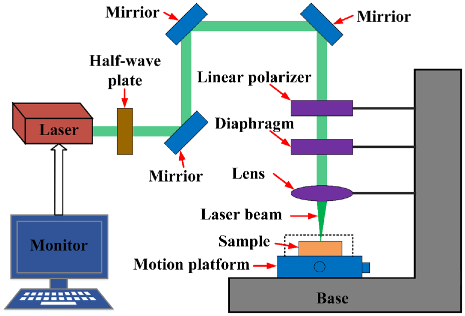
Schematic diagram of the laser system.
Main parameters of the laser.
OFHC-TU1 was selected as the experimental material in this work. The dimensions were 30 mm × 12 mm × 5 mm. The chemical composition and main physical properties are listed in Tables 2 and 3. The workpiece was clamped onto the fixture, and a pre-cut process was conducted to achieve an ideal flatness.
Chemical composition of OFHC-TU1.
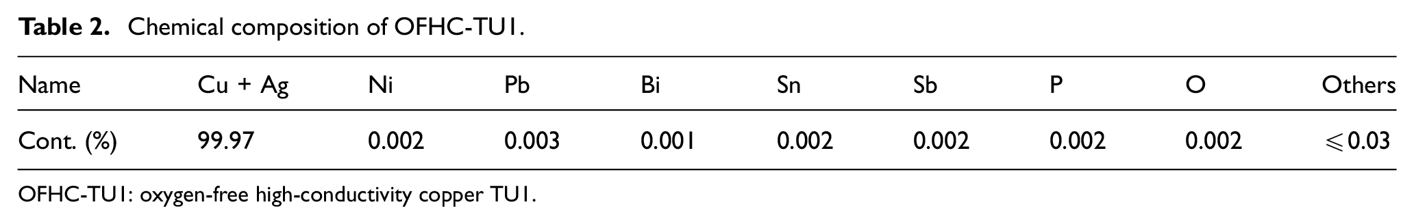
OFHC-TU1: oxygen-free high-conductivity copper TU1.
Physical properties of OFHC-TU1.
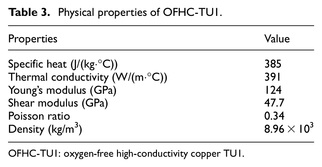
OFHC-TU1: oxygen-free high-conductivity copper TU1.
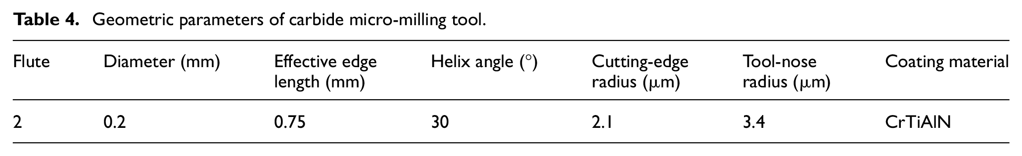
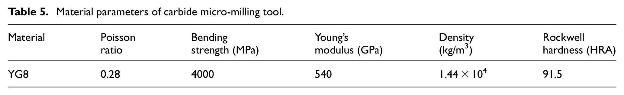
The commercial spiral carbide micro-milling cutters were selected in this work. The geometric parameters and material properties are given in Tables 4 and 5, respectively. The tool-nose radius (re) and cutting-edge radius (rn) were measured to be about 3.4 and 2.1 μm, respectively, using a 3D measurement laser microscope (LSM 700, Germany).
Geometric parameters of carbide micro-milling tool.
Material parameters of carbide micro-milling tool.
Experimental scheme
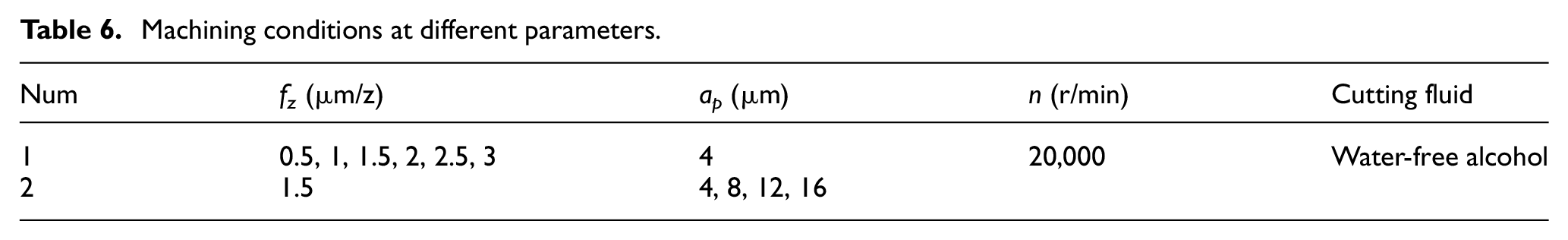
To achieve micro-grooves with superior machined quality, a series of parametric experiments were carried out to investigate the effects of cutting parameters on surface roughness (Ra) first. According to the previous research results and experiences, 22 the spindle speed (n) was kept as a constant. The input variables were feed per tooth (fz) and depth of cut (ap), and six levels and four levels were set, respectively. The detailed machining conditions are given in Table 6.
Machining conditions at different parameters.
Then, HAR micro-groove experiments were conducted using the optimum conditions obtained from the parametric experiments. The nominal total depth of the micro-groove was 0.5 mm, and the aspect ratio was 2.5. HAR micro-grooves were completed by two micro-milling tools, named T01 and T02, respectively. The aim of T01 is the pre-profiling machining of the groove with a total depth of 0.48 mm. T02 is used for the finish machining of the HAR micro-groove starting from the original workpiece surface, and the total milling depth is 0.5 mm. The processing conditions of the HAR micro-groove are listed in Table 7.
Processing conditions for HAR micro-groove.
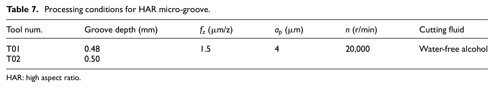
HAR: high aspect ratio.
The cutting force signals were recorded and analyzed by NI-DAQ software. Absolute alcohol cutting fluid was employed for all the experiments, and the mass fraction of ethanol was equal to or more than 99.7%. It is worth mentioning that the temperature produced in micro-milling process is pretty low, which cannot result in the direct evaporation of the water-free alcohol. Besides, the residual cutting fluid after the experiments volatilizes quickly, which strongly ensures the worktable environment. For the laser deburring, to effectively minimize the dimension of micro-burrs, based on the preliminary research results, the scanning speed was set at 5 mm/s, the pulse repetition rate and laser energy employed were 50 kHz and 256 mW, respectively.
Characterization and measurements
The surface roughness was observed by a 3D confocal surface topography instrument (Phase Shift MicroXAM-3D, United States) in the feed direction, and six different positions were selected for obtaining the average value. The surface morphology, top burr formation, and tool wear were analyzed by a scanning electron microscope (Hitachi S3400N, Japan). The top burr variation before and after the laser deburring was observed by a laser scanning confocal microscope (OLS4100, Germany).
Results and discussion
Effects of cutting parameters on surface quality
The results of surface roughness (Ra) with the variables of fz are shown in Figure 3. In micro-milling, the cutting parameters (e.g. undeformed chip thickness) used are in the same order of magnitude with the cutting-edge radius, which results in the effective cutting rake angle become a large negative rake angle. When fz is reduced to an absolute value, the ratio of the cutting thickness and cutting-edge radius becomes very small, and the significant size effect occurs, which strictly affected the material removal mechanism and chip formation process. Meanwhile, the non-cutting behavior (like erasing, extrusion, and plowing) in micro-milling dominates the primary cutting area, which could deteriorate the surface quality and result in unusual changes of the cutting forces.23,24 As shown in Figure 3, Ra decreases at first when fz rises from 0.5 to 1.5 μm/z, then it gradually has an increasing trend as the fz continues to increase to 3 μm/z. It can be discovered that all the values of Ra fluctuate around 100 nm with a more satisfactory level, and a minimum Ra of 75 nm is obtained when fz = 2 μm/z. Moreover, the changes of the top burr dimension as shown in Figure 3(b) are basically the same as that of Ra. When fz decreases from 1.5 to 0.5 μm/z, the burr volume becomes more prominent gradually. Therefore, it is not the wisest choices to achieve the ideal surface quality by only reducing the cutting parameters blindly in micro-milling.
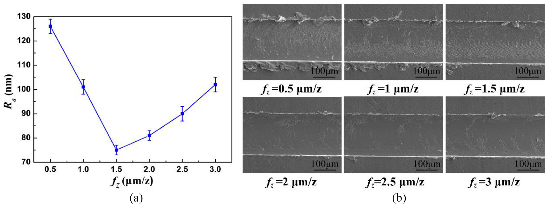
(a) Changing curve of Ra with fz and (b) surface morphology of micro-grooves under different fz.
The influence of the depth of cut on the bottom surface roughness is displayed in Figure 4. It can be discovered that the impact of ap on Ra is different from that of fz. The growth of ap (from 4 to 16 μm) has caused a steady rise in Ra. The maximum and minimum values of Ra obtained are 70 and 116 nm, respectively. The larger the ap becomes, the faster the Ra increases. Besides, a certain number of burrs are observed on both sides of the machined grooves from Figure 4(b), and more burrs are formed on the down milling side than that of the up milling side. The increase in ap leads to a more considerable burr height.
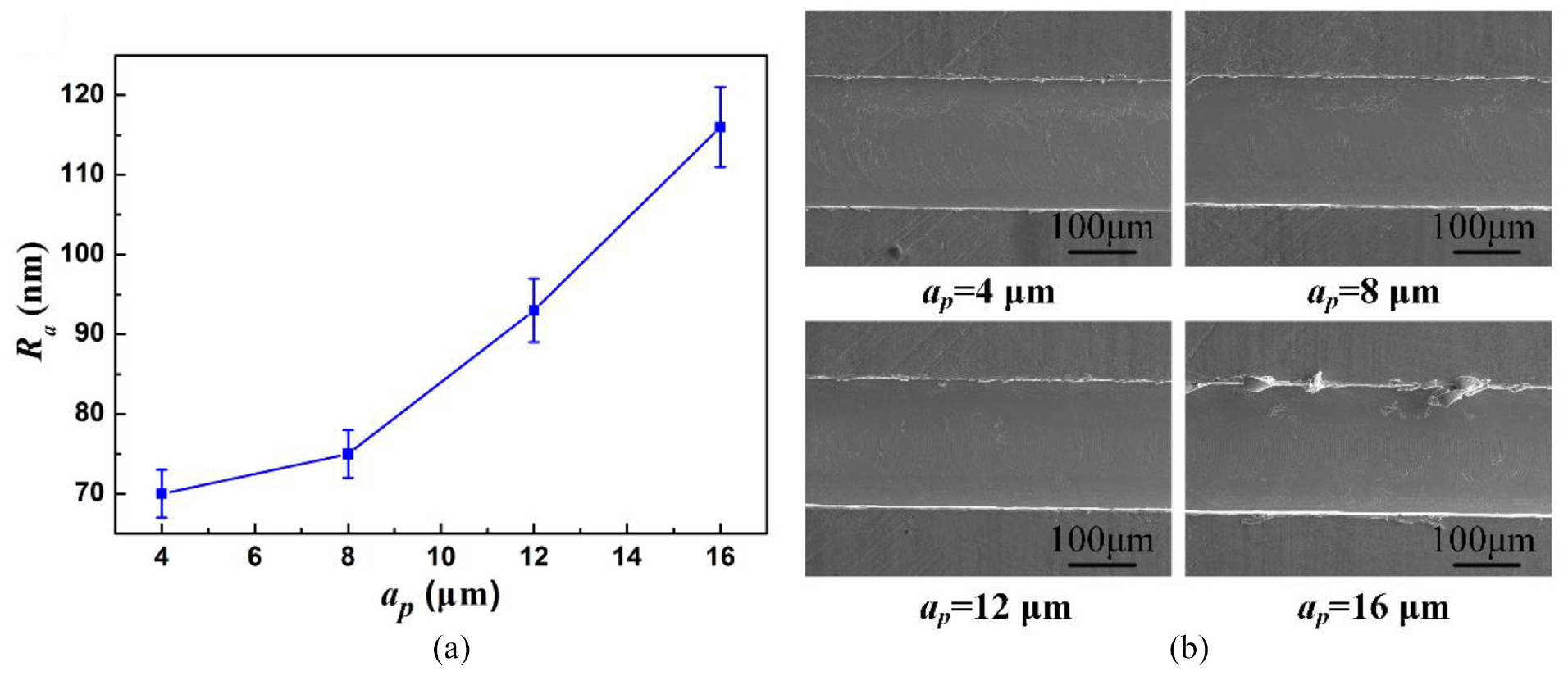
(a) Changing curve of Ra with ap and (b) surface morphology of micro-grooves under different ap.
From the analysis above, within the range of parameters studied, to achieve superior machined quality, the preferred cutting conditions obtained are fz = 1.5 μm/z, ap = 4 μm, and n = 20,000 r/min, which could provide a valuable reference for the experimental study of micro-grooves with a HAR.
Analysis of cutting forces
From the results above, a HAR micro-groove is produced under the preferred cutting conditions (fz = 1.5 μm/z and ap = 4 μm when n = 20,000 r/min). The changes of cutting forces of T01 and T02 with the cutting cycles increasing are given in Figure 5. For T01, both the main cutting force (Fx) and feeding force (Fy) rise gradually as the milling distance increases and Fx is always larger than Fy for the whole milling process. In the initial stage, the cutting forces are smaller, for example, the values of Fx1 and Fy1 in the first pass are 0.35 and 0.19 N, respectively. Throughout the first 30 cycles, Fx1 and Fy1 are growing at a relatively faster rate, and then they become stable. While, after the 70 periods, Fx1 and Fy1 continue to be a faster-growing stage. Moreover, the wear evolution of the carbide micro-milling tool could be divided into three stages (initial-wear, steady-wear, and severe-wear stage), which is consistent with the change trend of cutting forces obtained in this work. In fact, the influence factors of tool wear are varied, mainly including the tool material, geometric angles, coating material, cutting parameters, thermo-mechanical coupling effect, system stability, and so on.25–27 With the milling distance increasing, the total volume of the materials removed accumulates gradually, and the wear degree of the micro-milling tool becomes severer. Because of the size effect in micro-milling, the plowing effect is enhanced, and then the contact area between the workpiece material and the tool bottom becomes larger, which results in the aggravation of the friction and extrusion. The increase ratio of friction force enhances the total force. When the cutting-edge radius (rn) increases to a certain extent, the instantaneous cutting thickness becomes less than the minimum cutting thickness, and chips are no longer produced in the milling process. Furthermore, the forces become larger with the more intense plowing and extrusion effect. This is why some scholars often combine the cutting forces (cutting force signal) with tool wear, 28 such as evaluating the tool wear by determining the variation amplitude of the cutting force relative to the initial value of the normal wear stage of new tools.
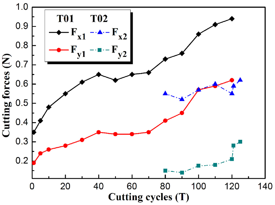
Changing curve of the forces with the cutting cycles.
For the second tool (T02) in the finish machining process, it can be seen from Figure 5 that the variations of Fx2 and Fy2 are totally different from that of Fx1 and Fy1 above. The force signals of Fx2 and Fy2 started to be recorded from the 80th cycles, and they have been increasing slowly as the cutting cycles accumulate to 120. Then, Fx2 and Fy2 begin to increase rapidly from the 121st cycle. This indicates that the T02 is involved in milling from the 80th cycle due to the tool wear of the T01 in the rough machining stage.
The tool wear diagrams of T01 and T02 are displayed in Figure 6. Figure 7 shows the microscopic wear morphology and energy dispersion spectrum (EDS) analysis of T01. It can be seen from Figure 7(a) that the tool wear situation of T01 is extremely serious and the tool failure has already occurred before the rough machining process is finished. From the EDS analysis result of the worn-out tool T01 shown in Figure 7(b), it can be noticed that the material composition of the tool-nose mainly contains the elements W, C, and Co. This means that most of the CrTiAlN coating material has fallen off, with exposing a large area of cemented carbide matrix. The tool-nose is also subjected to the micro-chipping and slight fracture (Figure 6(a)). By further observation, no adhesive OFHC material is found on the tool-nose. Therefore, the dominant wear forms of T01 are mainly characterized by the coating shedding, micro-chipping, and slight fracture. The wear degree of T02 is much lighter than that of T01, due to the relatively short actual milling distance. It can be noticed from the image in Figure 6(b), the tool-nose of T02 is still in a relatively sharper state. Moreover, the thermo-mechanical coupling effect is also a primary factor for the severe tool wear in micro-milling. In metal cutting process, the thermo-mechanical coupling refers to the interaction of the heat and cutting force. 29 Most of the work done by the plastic deformation and friction in the plastic deformation zone is converted into the cutting heat. Then, the temperature of the tool surface increases sharply, which greatly shortens the tool service life. On the other hand, the temperature rise of the workpiece also deteriorates the machined accuracy and the surface roughness.30,31
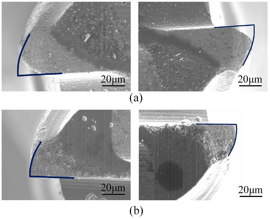
Tool wear of (a) T01 and (b) T02.
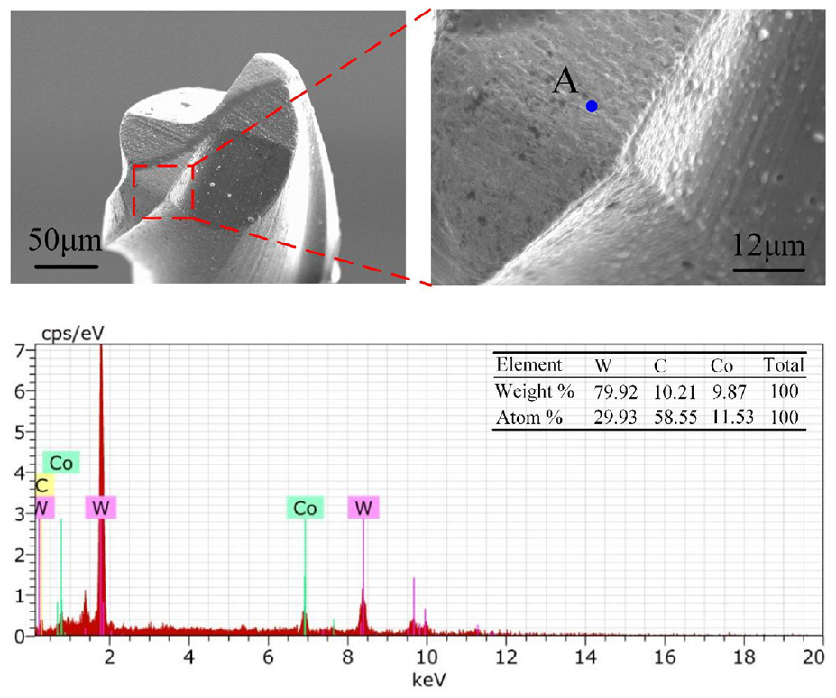
(a) Microscopic wear morphology of T01 and (b) EDS analysis of point A.
Analysis of surface quality
The surface morphology of the micro-groove obtained is given in Figure 8. It can be seen from Figure 8(a) that the obtained surface of the down milling side by T01 is a little out-of-flatness with some significant machining edges on the groove bottom. The primary reason is that the carbide tool (T01) has been severely worn out in the later period, which causes large rn and remarkable size effect. Severe side flow occurs in a small part of the unchipped material under the rolling action of the flank face. Then, the material residual area and height on the machined surface become large due to the existence of these micro-edges, thus forming an inferior groove bottom quality as shown in Figure 8(a).
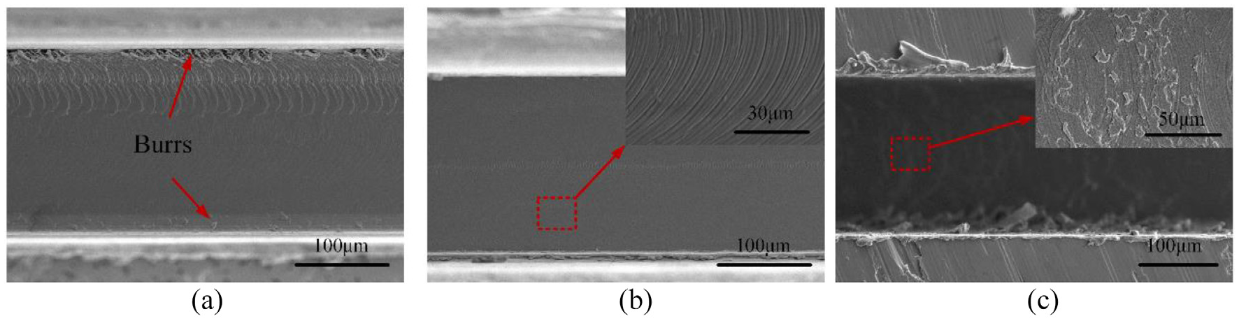
Surface morphology of micro-groove bottom by (a) T01 and (b) T02 with absolute alcohol and (c) in dry condition.
The machined surface obtained after the finishing process of T02 becomes much smoother from the observation in Figure 8(b). The tool marks are relatively well-distributed and more intensive without apparent edges, and the side burrs in the inner wall have also been obliterated. Through careful measurement, the average bottom surface roughness Ra is estimated to be a relatively satisfactory value of 68 nm. Moreover, a comparison surface morphology of micro-groove generated without any coolant or lubrication is given in Figure 8(c). It can be clearly noticed that the surface quality of this micro-groove is inferior with a more significant number of burrs in the inner wall and bottom surface due to the active extrusion of the carbide micro-milling tool. The average Ra is measured to about 119 nm, which is much larger than that of 68 nm. This indicates that the water-free alcohol cutting fluid plays a significant positive role for achieving a higher surface quality of HAR micro-grooves when utilizing carbide micro-milling tools.
The burr formation on top surfaces and the entrance is shown in Figure 9. As can be discovered, the top burrs in Figure 9(a) are much larger and denser, which is the nonlinear accumulation result in the generation process of the deep micro-groove. The formation of top burrs is a combination of chip tearing at the groove-edge and the extrusion effect of the cutting-edge. When the actual cutting thickness is close to the minimum cutting thickness, under the action of cutting-edge, the workpiece material is subjected to high extrusion stress, and flows out to the free surface to form the top burrs. Moreover, the top burrs become more prominent due to the helical angle of the carbide micro-milling cutter, because the side flow of deformed material becomes more serious when the helical angle exists. With the increase in the groove depth, the milling distance increases continuously, and simultaneously, the carbide tool wears very severe. The expansion of the cutting-edge radius due to the tool wear results in a larger effective negative rake angle, which aggravated the friction and plowing between the rake face and chips. When the increased cutting-edge radius of the worn-out tool is approximately equal to or even larger than the cutting thickness, the contact state between the cutting tool and workpiece is mainly the friction and extrusion effect, and no chips are produced at this time. Elastic and plastic deformation occurs in the metal cutting layer due to the friction and extrusion effect, resulting in relatively large burrs on top surfaces of the micro-groove. Moreover, the burr size of the up milling side is much smaller than that of the down milling side. The maximum height of the down and up milling sides is about 72 and 21 μm, respectively.
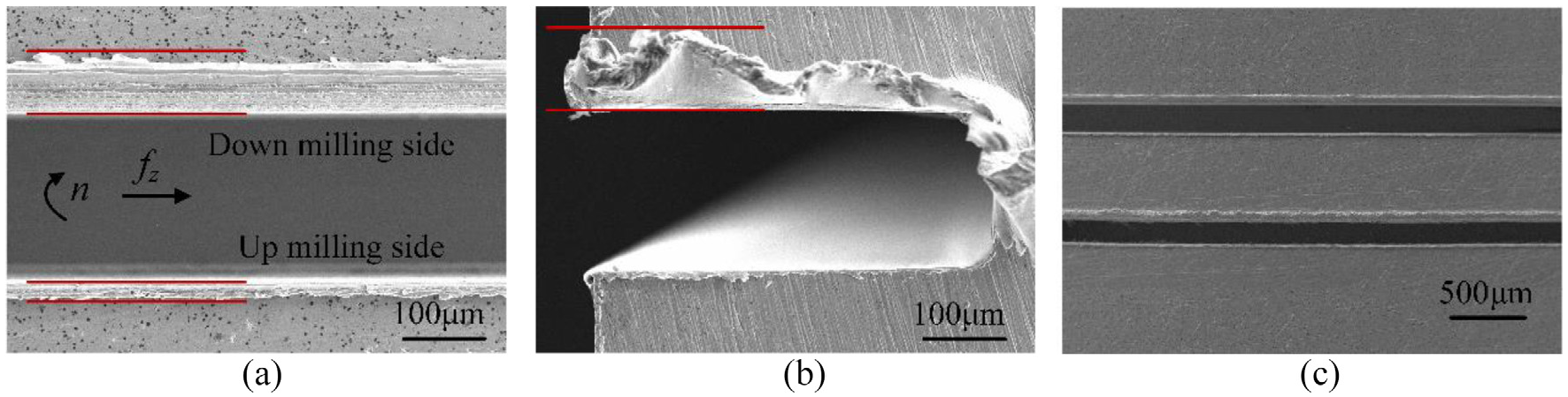
Burr formation on (a) top surfaces, (b) the entrance, and (c) the top view comparisons in absolute alcohol and dry condition.
Furthermore, the cut-in burr is likewise heave, and the maximum height of the down milling side as shown in Figure 9(b) is about 99 μm. According to the results of stress distribution produced by chips, the formation of cut-in burrs is also attributed to the plastic side flow of materials, and the formation mechanism is displayed in Figure 10. When the micro-milling cutter contacts the micro-groove in the beginning, the plastic deformation of the workpiece material occurs under the intense extrusion of the cutting-edge radius. When the pressure is greater than the shear yield strength of the material, the material of the workpiece flows sidewise toward the flank face with the lowest resistance, and flows out along the free surface AB as shown in Figure 10. As the cutting-edge moves forward, it is difficult for the cutting-edge to involve in actual cutting effect on the accumulated materials at the entrance of the micro-groove, which leads to the remaining materials being collected, and finally to form the cut-in burrs.
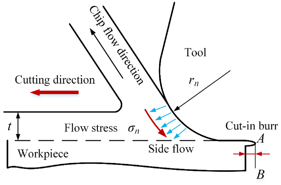
Formation mechanism of the entrance burr.
Laser deburring process of top burrs
Burrs formed on the surfaces greatly degrade the quality and performance of micro-products. 32 The deburring processes, such as mechanical, chemical, thermal, ultrasonic processes, and so on, have been widely investigated. However, the deburring operation in micro-milling is more challenging and difficult in contrast to the macro-milling, 33 and many technologies are no longer suitable for the micro-structures. Laser technology is to utilize the interaction characteristics between the laser beam and materials to realize the surface treatment and micro-fabrication of workpieces. 34 The outstanding advantages of laser technology are non-contact machining, non-pollution, high efficiency, and so on. In this work, the laser deburring method is employed to remove the top burrs of the OFHC-TU1 HAR micro-groove obtained above. During the laser deburring, the precise location of micro-burrs is realized by X and Y micro-mobile platform. The laser scanning path is parallel to the feed direction of micro-milling cutter. The real-time removal process is observed by charge-coupled device (CCD) microscope. Figure 11 shows the schematic diagram of the laser deburring process in detail.
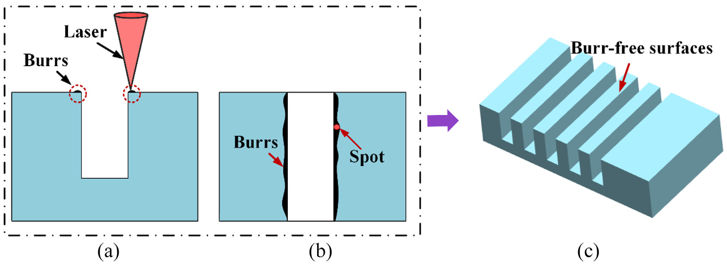
Schematic diagram of the laser deburring process: (a) side view, (b) top view, and (c) 3D image.
The basic principle of laser deburring technology is mainly based on the outstanding characteristics of the laser in terms of high intensity, high energy density, sharp focusing, and good directivity. The laser beam emitted from the laser could focus into different diameter spot when passing through the optical device. For the micro-burrs with different sizes, the energy density of the laser is adjusted by controlling the focus spot of laser beams of different diameters, and the burrs are removed instantaneously when the laser spot scans the workpiece surface.
The 3D images of HAR micro-groove top surfaces before and after the laser deburring process are shown in Figure 12 by utilizing the preferred laser parameters given in section “Experimental setup and methodology.” The micro-burr sizes on both top sides are significantly reduced after the laser deburring, particularly for the down milling side. The burr height of down milling side as shown in Figure 12(a) is measured to be about 40.6 μm, but the corresponding size as shown in Figure 12(b) is only a few microns. This indicates that the laser deburring process is sufficient for the HAR micro-grooves by repeated laser irradiation.
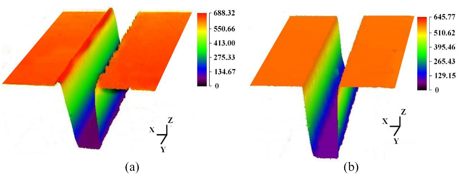
3D images of top surface (a) before and (b) after the laser deburring process.
Conclusion
Experimental investigations on OFHC-TU1 micro-grooves with HAR have been carried out to have a preliminary explore on the machined surface quality, cutting forces, and tool wear. Results show that the surface roughness (Ra) of HAR micro-groove is heavily dependent on the feed per tooth and depth of cut. A satisfactory Ra of 68 nm is obtained in the preferred machining conditions (fz = 1.5 μm/z and ap = 4 μm when n = 20,000 r/min). The cutting force variations of the first tool (T01) mainly include three stages (initial stage, stable stage, and rapid growth stage), while the forces of the second tool (T02) are at a relatively low level in the finish machining stage. The tool wear of the first tool (T01) is pretty severe and mainly characterized by severe coating shedding and micro-chipping. The wear degree of the second tool (T02) used for the finish machining process is relatively slight. Moreover, the laser deburring process is proved to be effective in removing the micro-burrs on top surfaces of the HAR micro-grooves, and required burr-free top surfaces are achieved.
Micro-grooves have become an increasingly useful surface structure in a wide range of applications, including terahertz (THz) slow-wave structure, micro-heat exchanger, surface texture, and so on. This work is expected to be valuable in improving the machined surface quality of micro-grooves with a HAR. Further studies should focus on the other difficult-to-machine materials and fabricating high-performance diamond tools.
Footnotes
Acknowledgements
The authors greatly acknowledge the experimental help of Dr. Xingsheng Wang from Nanjing Agricultural University and Dr. Youqiang Xing from Southeast University.
Declaration of conflicting interests
The author(s) declared no potential conflicts of interest with respect to the research, authorship, and/or publication of this article.
Funding
The author(s) disclosed receipt of the following financial support for the research, authorship, and/or publication of this article: This research is supported by the National Natural Science Foundation of China (No. 51575268), Defense Industrial Technology Development Program (No. JCKY2018605C018), the Natural Science Foundation of Jiangsu Province (No. BK20190066), the Aeronautical Science Foundation of China (No. 2017ZE52055), and National Postdoctoral Foundation of China (Nos. 2017M610327 and 2018T110493).