
Abstract
In order to achieve the special functional surfaces machining, a two-round design method for the ultra-precision machine tool design is proposed in this article. This method starts from the engineering design experience; by alternately using the simulation and experiment, the “design-simulation-experiment-simulation-redesign experiment” strategy is employed to the machine tool design. The main influence factors for all of the specifications are determined by this alternating strategy. The analysis of the machine tool performance and the surface generation simulation are well integrated, and the test software is used early at the design stage to estimate the predicted surface. This design method is used for an ultra-precision flycutting machine tool design for potassium dihydrogen phosphate crystal machining, and the results show that by the two rounds of design and modification, the final machine tool meets the processing requirements well. It is believed that the proposed model can be successfully applied to an ultra-precision machine tool designed for achieving strict processing requirements.
Introduction
Precision machines are essential in modern industry since they directly affect machining accuracy, repeatability, productivity and efficiency.1,2 Nowadays, the industry and institutes are aimed at creating high-precision products not only for changing our lives in terms of increased living standards but also for national defense, energy, space exploration, and so on. Design for higher precision is becoming more and more important due to the rapidly increasing need for high-accuracy machines, instruments, and consumer products.3,4 It puts forward more harsh requirements for the new-generation machine tool, for example, the machining size becomes larger and the topography requirements of the machined surface become stricter. It is crucial to design such a machine tool with these requirements quickly, because of a constant competition for leadership in the market and the urgent need of science and technology.
There are a number of publications on precision machine tools design. Huo et al.5–8 proposed a comprehensive integrated dynamics-driven design and modeling approach and developed an ultra-precision micro-milling machine tool. Shore et al.9,10 developed an ultra-precision grinding machine tool named “BOX,” which emphasizes the dynamic performance of the machine tool. In order to cope with the low-productivity problem for micro-/nano-machining of high-precision molds or miniature parts, a highly accurate and productive machining center has been designed and developed by Wang et al. In this design, the counter-balance axis is used to eliminate all possible vibrations generated by the rapid moving components.11–13 For the purpose of realizing the small-size workpiece machining while increasing its machine accuracy, Brecher et al. developed two high-precision machine tools following a compact design method by reducing the overall machine dimensions. They pointed out that the compact design philosophy can not only enhance the dynamic performance of the machine tool, but also minimize accelerated masses, thermal errors, and error activating cantilevers such as Abbe error, Pivot error, and Steiner distance. 14 Shore et al. 15 also used this method to design a compact six-axes ultra-precision machining center, which was configured to offer compact size, eased automation, and in situ metrology. However, for machine tool design to realize the complex requirements of machined surface, such as the machine tool for potassium dihydrogen phosphate (KDP) crystal machining, large optical elements, and micro mold processing, it is difficult to assure the machine performing right at the first setup. When designing such a machine tool, it is unpractical to consider all of the requirements at the design stage and it is difficult to determine the correlations between influencing factors and each specification clearly at the design stage. Taking into account all design specifications at the same time in the design stage will put the design process in trouble, and even make designers feel that they do not know how to start designing. For the ultra-precision flycutting machine tool design, a dynamic design approach has been proposed in our previous study, but it mainly focused on a single specification to deal with the power spectral density 1 (PSD1) problem. 16 But with the requirements of improving the machined surface, some other specifications which do not meet the requirement are found. The design approach proposed previously is less effective.
In this article, a two-round “simulation and experiment” design approach is proposed to deal with such a problem and employed for design of a new ultra-precision flycutting machine tool. The proposed approach permits analysis and optimization of the overall machine tool dynamics and machining performance during the design stage by the interaction of the simulations and experiments. Based on the proposed design approach, the major factors influencing the machined surface are found in the first-round designing and optimized in the second-round designing process. Preliminary machining trials have been carried out, which provided the evidence of this approach being able to assure that the machine functions satisfy the machining requirements.
The schematic of the two-round “simulation and experiment” design approach is shown in Figure 1. The design process generally starts with analysis of the machining requirements, and selection of the basic machining requirements, based on which we can determine the influencing factors at the design stage as the first-round design target. To achieve the first-round requirements, the machine tool behaviors have to be well understood at the conceptual design stage, which contains the design of kinematic chain, configuration and components. The kinematic chain and configuration determine the rough sketch of the machine tool. The component design determines the details of the machine tool, which mainly contain the mechanical components’ design, the electronic drives system selection and control system design. 17 After the components’ design, a simulation model containing finite element (FE) model and mathematical model are established accurately. The influence of the interference such as the cutting force, slide straightness, and machining parameters is considered to forecast the performances of the machine tool and predict the topography of the workpiece. Then, the detection software is used to estimate the predicted surface and compare with the first-round requirements; if the predicted topography satisfies all of the requirements set in the first-round design, the prototype will be built according to the parameters used in the simulation model. Otherwise, the simulation parameters will be adjusted until the prediction topography satisfies the first-round requirement.
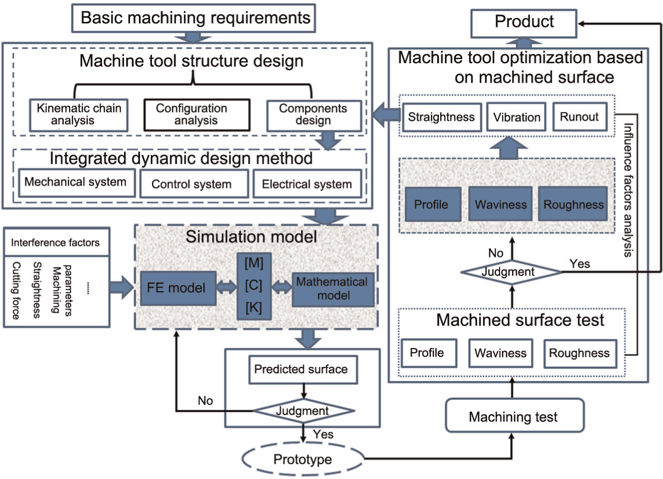
Schematic of the two-round “simulation and experiment” design approach.
After the prototype is built, the machining trials are carried out. The machined surface is tested and compared with the requirements. The evaluation specifications which do not satisfy the requirements are found, and the major factors influencing this are fully analyzed by combining experiment and theoretical analysis. If all the specifications satisfy the requirements, then the design is finished, and the prototype is the finished product. But if there are any specifications not satisfying the requirements, the second-round simulation will be carried out. In this step, the major influences of design specifications which do not satisfy the requirements are optimized and used to predict the surface morphology in multi-scale. The test software is used to detect the predicted surface morphology in different scales. The test results are compared with the machining requirements; if the test results satisfy the machining requirements, the optimized parameters are used to improve the prototype. Otherwise, the design specifications should be adjusted until the test prediction results satisfy the machining requirements. The design of an ultra-precision flycutting machine tool used for KDP crystal machining is used as an example to describe the method in details.
KDP machine tool design
The material of the workpiece is KDP crystals, which have good nonlinear optical and electro-optical properties. It mainly functions as harmonic frequency converter in modern high-energy solid-state lasers, polarization rotators in Pockels cells and laser fusion system in the Inertial Confinement Fusion (ICF) program.18,19 The laser damage threshold of the KDP crystal, as an important optical property for the ICF program, is not only affected by the material qualities of KDP crystal but also by the topographic properties of machining surface. 20 Consequently, the KDP crystal has extremely harsh requirements of topography. The specifications of the machined surface are as follows: 21
Specification 1. Roughness values (Ra) less than 3 nm in the range 0.01–0.12 mm;
Specification 2. Root mean square (RMS) no more than 4.2 nm and PSD2 better than 15 nm2 mm in the range 0.12–2.5 mm;
Specification 3. RMS less than 6.4 nm and PSD1 better than 15 nm2 mm in the range 2.5–33 mm;
Specification 4. Gradient root mean square (GRMS) better than 11 nm/cm in the range over 33 mm.
If the quality of the machined surface does not satisfy the requirements, it commonly causes damages to the laser, as well as energy loss and inability to focus the energy on target.22,23 Therefore, the factors of surface topography influenced by the machine tool performance must be carefully considered in the design stage of the machine tool. Experience on the roughness and flatness design and knowledge of the main influencing factors on them are readily available, while for the PSD1 and PSD2 design, the experience is lacked, and they are affected by too many influences to determine the major influencing factors; it is difficult to determine the design specifications of the machine tool in the design stage, and the only way to identify them is by experiments. Therefore, the roughness and GRMS specifications are selected as the first-round targets, and the PSD specifications are left in the second round. The major influencing factors for PSD specifications will be found in the first round and optimized in the second round to meet the machining requirements (Figure 2).
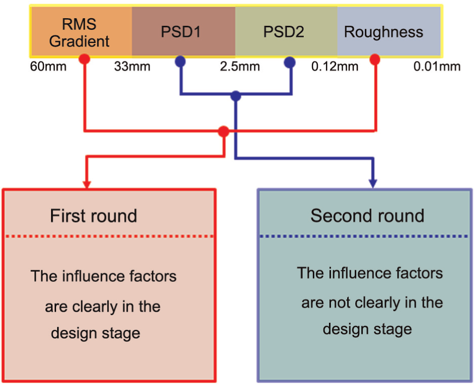
The machining requirements analysis.
The first-round machine tool design
Kinematic chain analysis
The purpose of this machine is to produce flat half-meter scale optics; therefore, the forming movement of the machine tool constituted by the workpiece feed movement in horizontal direction and the cutting tool feed movement in vertical direction are needed. Considering the material characteristics of KDP crystal, such as soft, fragile, gyroscopic and thermally sensitive, single-point diamond flycutting is used to machine such type of crystal by which the influence of material anisotropy on surface quality is reduced for its single-cutting direction.
The simplified kinematic chain of the machine tool is proposed in Figure 3(a)). The diamond cutting tools are installed in a large flycutting head which is driven by the spindle motor. The feed of the workpiece is achieved by a horizontal-axis slide driven by linear motor. With only two axes, the flat components’ processing can be achieved. This kinematic chain has a short structure loop, which contributes to the machining accuracy. 24
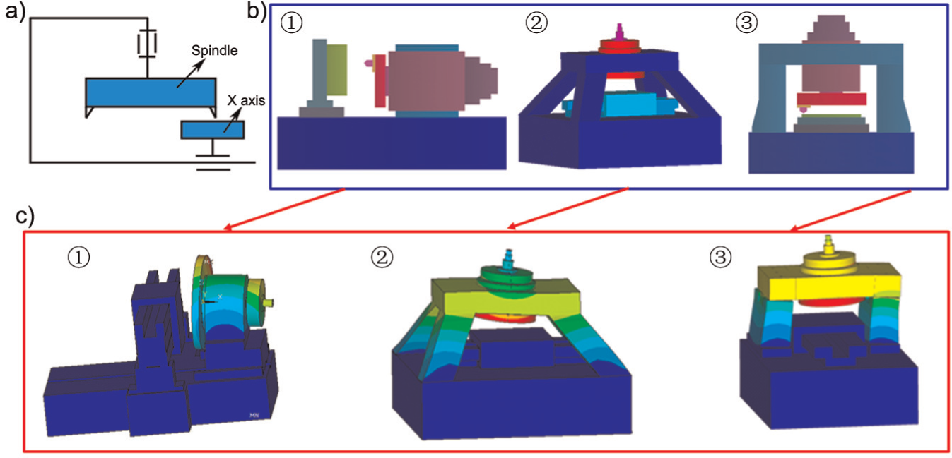
The configuration design of the machine tool. a) kinematic chain of the machine tool; b) three typical configurations; c) FE analysis of each configuration.
Configuration design
Three typical configurations are proposed according to the kinematic chain proposed in Figure 3(a), which includes an open frame structure as well as two closed structures as shown in Figure 3(b). The structural loop of the first scheme is an open frame (horizontal type), which is compact, short, easy to assemble and access the work zone, but sensitive to thermal and mechanical deformation.
The second and third one are closed frame and have symmetric structure, which can improve the rigidity of the machine tool and reduce thermal deformation. Heat from the spindle bearings and motor creates a symmetrical temperature profile in the bridge when the spindle is centered, reducing squareness errors caused by thermal distortion of the bridge and providing a stiffer structural loop between the tool and the workpiece. It is suitable for machining larger size workpieces. The dynamic performances of the machine tool play an important role in the surface quality and sub-surface damage of the machined surface. To obtain better dynamic performances of the machine tool, the modal FE analysis has been carried out on the three machine tool configurations. From the results shown in Figure 4, it can be found that the first-order natural frequency of the open frame is 80 Hz, the pyramid structure is 112 Hz, and the gantry structure is 116 Hz. In addition, the modal density (number of modes per frequency range) of the test object is also used to judge the dynamic performance. The dynamic response FE analysis of the three configurations is shown in Figure 5; it shows that the open frame has lower vibration frequency than the closed frame, it has the same static stiffness as that of the closed frames, while the static bandwidth is shorter, and during 0–1000 Hz, it has four obvious resonant responses, which indicates a bad dynamic performance. The two close structures have the similar dynamic performances, and the pyramid structure has no advantage in this design with the work space being larger than 500 × 1000 mm2. The two closed configurations have the same static stiffness and the static bandwidth, while during 0–1000 Hz, the pyramid configuration has three obvious resonant responses, and the gantry configuration has only two obvious resonant responses. Obviously, the gantry configuration has better dynamic performance. Therefore, the gantry structure is selected as the final configuration.
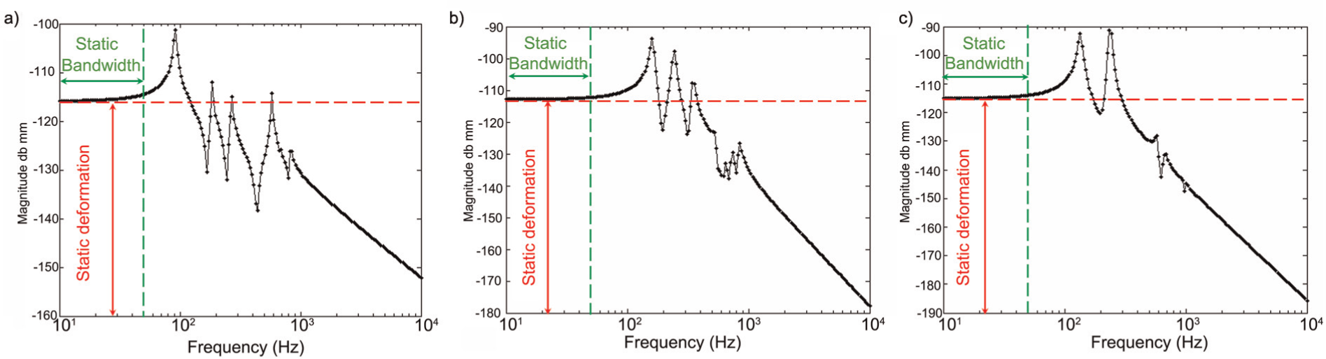
The dynamic analysis of the different configurations. a) dynamic response of the first configuration; b) dynamic response of the second configuration; c) dynamic response of the third configuration.
The detailed design of the machine tool.
The detailed design of the machine tool
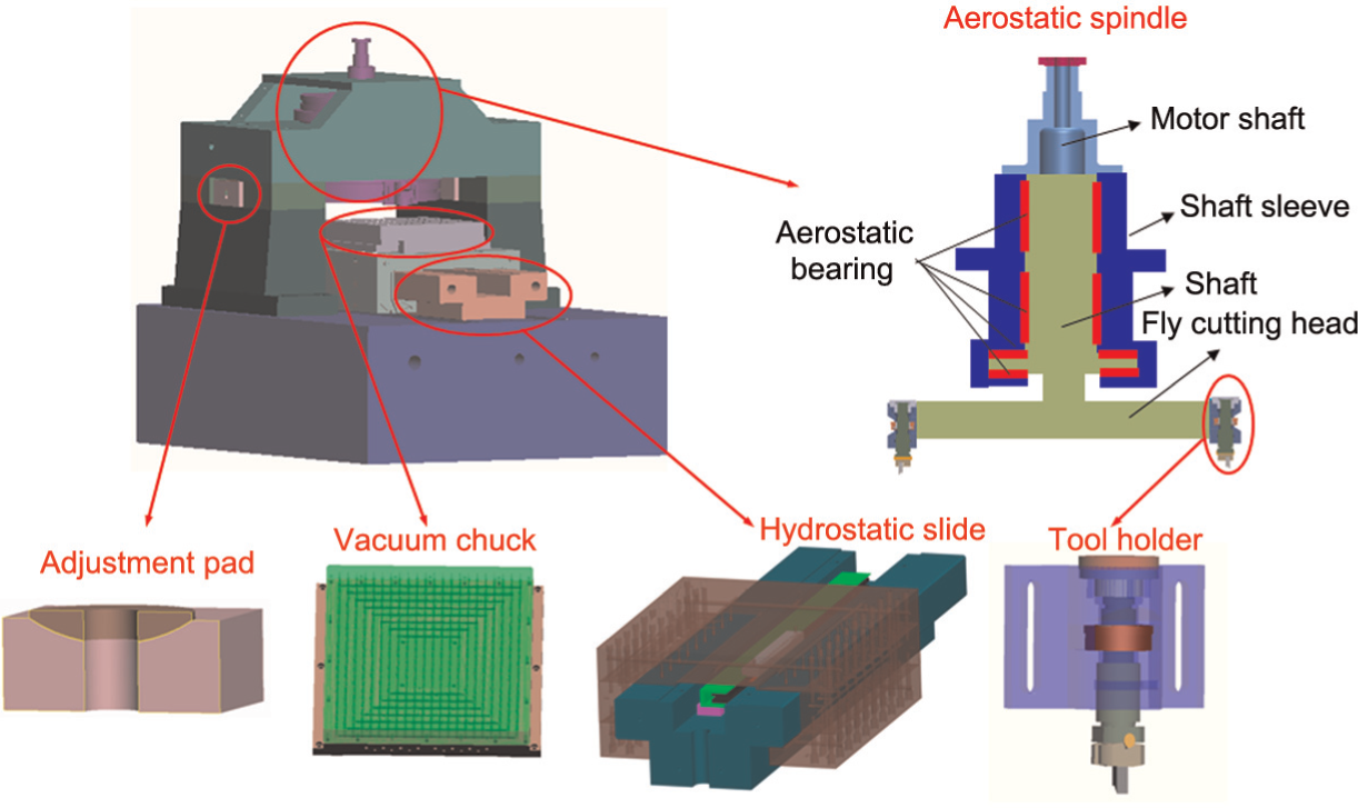
According to the analysis above, the configuration of the flycutting machine tool is given in Figure 5. A bridge supports a vertical-axis spindle and flycutter over a horizontal-axis slide. Mounted to the horizontal slide is a vacuum chuck that clamps the workpiece. The aerostatic bearings and hydrostatic bearings are used in the vertical-axis spindle and the horizontal-axis slide, respectively. The surface to be machined lays in a horizontal plane. The structure of the machine tool is composed by a machine tool bed, two columns, three adjustment pads, three spherical pads, a beam, an aerostatic spindle, a hydrostatic slide and two tool holders.
The machine tool design considering the GRMS target
Taking into account, the structure type and kinematic chain of the machine tool, it can be noted that the GRMS of the machined surface is mainly affected by the straightness of the slide. Currently, the straightness of the slide is realized by scraping and polishing processes; it is difficult to describe straightness shape by a close-form expression, but its basic shape is sine wave-like curve. In order to analyze the influence of the straightness on the GRMS quantitatively, the straightness is described by equation (1) approximately25,26
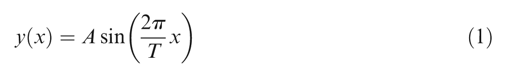
where A is the amplitude of the straightness, T is the wavelength of the function and x is the length of the slide. Figure 6 shows the typical shapes of the straightness.
The influence of the straightness on the GRMS.
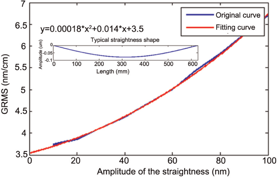
In order to evaluate the influence of the slide straightness on the GRMS, the simulations to the typical straightness shape with different amplitudes are carried out. Figure 3 shows that the GRMS trends change with the straightness amplitude. And through the curve fitting, relationship between the straightness and the GRMS value is obtained

From equation (2), it can be obtained that in order to make the GRMS no larger than 11 nm/cm, the slide straightness must be less than 0.169 um in 600 mm.
The roughness simulation
The roughness specification is required to be less than 3 nm in the range 0.01–0.12 mm. Figure 7 shows the cutting process of the flycutting. Theoretically, the arithmetic roughness (Ra) of a machined surface in single precision diamond cutting can be represented by 27
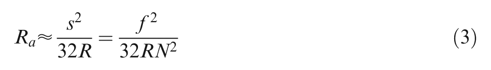
where s is the tool feed per revolution (mm/rev), f is the feed rate (mm/min), N is the spindle speed in revolution per minute and R is the tool nose radius. It can be seen that the roughness is inversely proportional to the tool nose radius and the square of the spindle speed, and directly proportional to the square of the feed. Therefore, in order to obtain better surface roughness, the machine tool must have an excellent slow feed performance, a high-speed spindle and a large tool nose radius. Considering the spindle runout and the material recovery; the roughness indicator designed as 1 nm; the tool nose radius selected as 5 mm; spindle speed as 300 r/min, according to equation (3); and the feed rate should be less than 60 µm/s; therefore, the hydrostatic slide must have an excellent slow feed performance. The simulated surface roughness is obtained as shown in Figure 8, with the feed rate of 60 µm/s. The simulation result shows that the roughness of the surface is 2 nm.
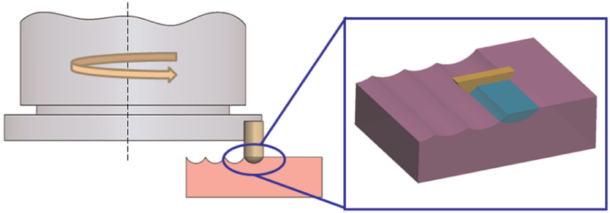
The ideal roughness of the flycutting.
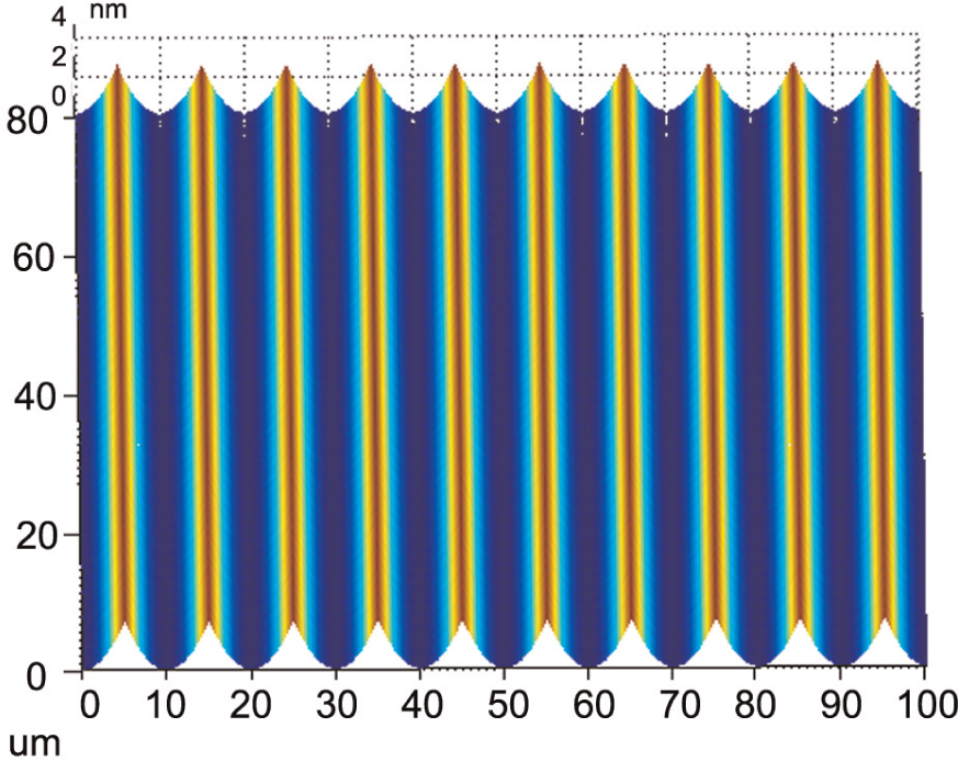
The simulation result of the roughness.
The prototype machine tool and experiments
A prototype is built as shown in Figure 9(a)), and the specifications of the machine tool are shown as follows. The horizontal straightness of the x-axis is measured by the photoelectric autocollimator. The measured result shows that the straightness of the x-axis is less than 0.14 µm in 600 mm as shown in Figure 9(b)). The micro step response of the x-axis is shown in Figure 9(c)), and the micro step could be with 30 nm resolution. In order to verify the stability of the low-speed performance of the slide system, the low-speed feed experiment is carried out. Figure 9(d)) shows the slide motion curve under the control commands 10 µm/s and 500-ms sampling period. It can be seen that the feed speed of the slide undulates within a range of ±0.1 µm/s, and actual position coincides well with the feed system command position. It shows that low-speed stability of the control system is excellent.
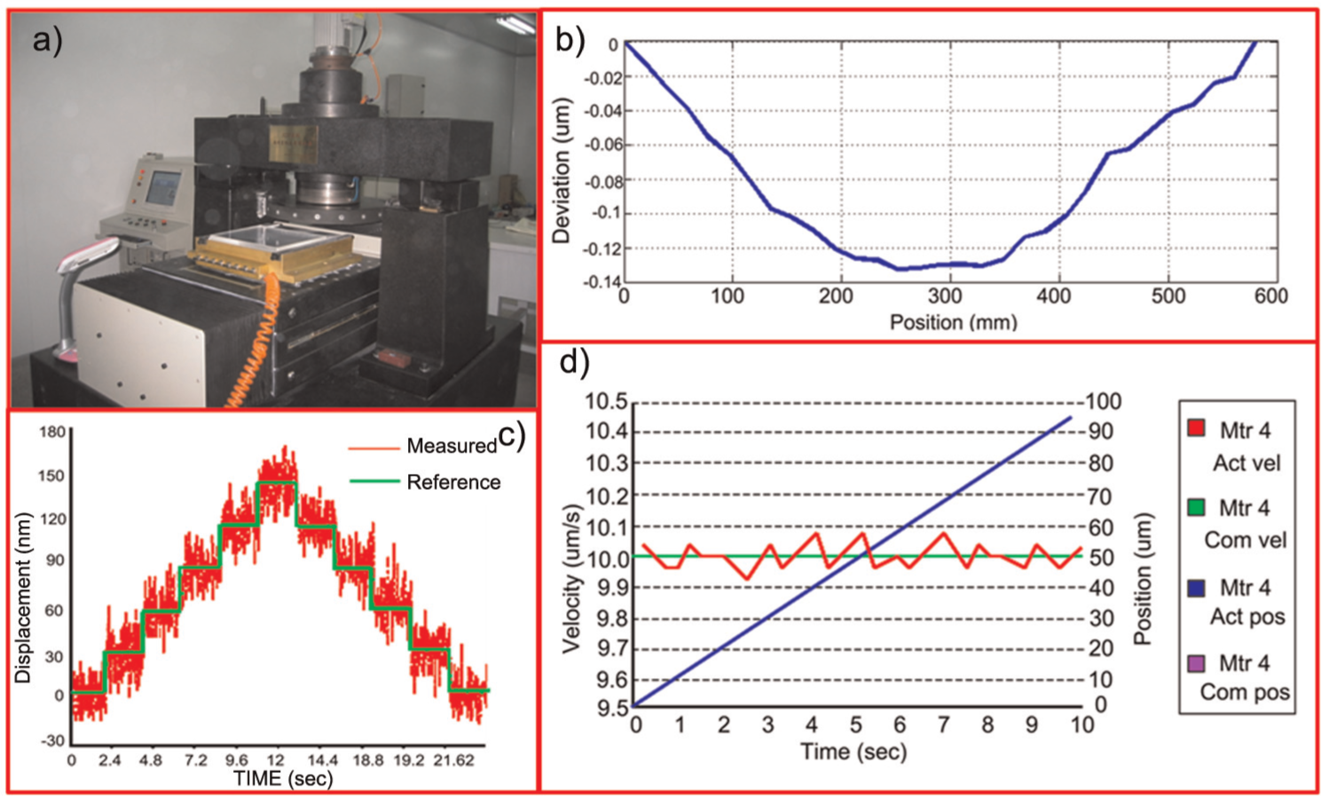
The prototype and the test result. a) prototype of the machine tool; b) straightness of the x-axis; c) micro step response of the x-axis; d) the slide motion curve.
The machining trials are carried out on this machine tool with a diamond cutter tool with −25° rake angle, 8° clearance angle, and 5 mm tool nose radius under the following processing parameters: a depth of cut of 15 µm, a feed rate of 60 µm/s, and a spindle rotational speed of 300 r/min.
The machining results are measured by a three-dimensional (3D) surface profilometer, Wyko RST-plus (Veeco Metrology Group, Santa Barbara, CA, USA). The measurement results, with only tip, tilt, and piston removed, are shown in Figure 10. The test results in different spatial scales show that the GRMS of the machined surface is 10 nm/mm and the roughness (Ra) is 2.3 nm, which satisfy the requirements. While PSD1 is 25 nm2 mm, the PSD2 is 23nm2 mm, which do not satisfy the requirements. This problem will be discussed and solved in the second-round design.
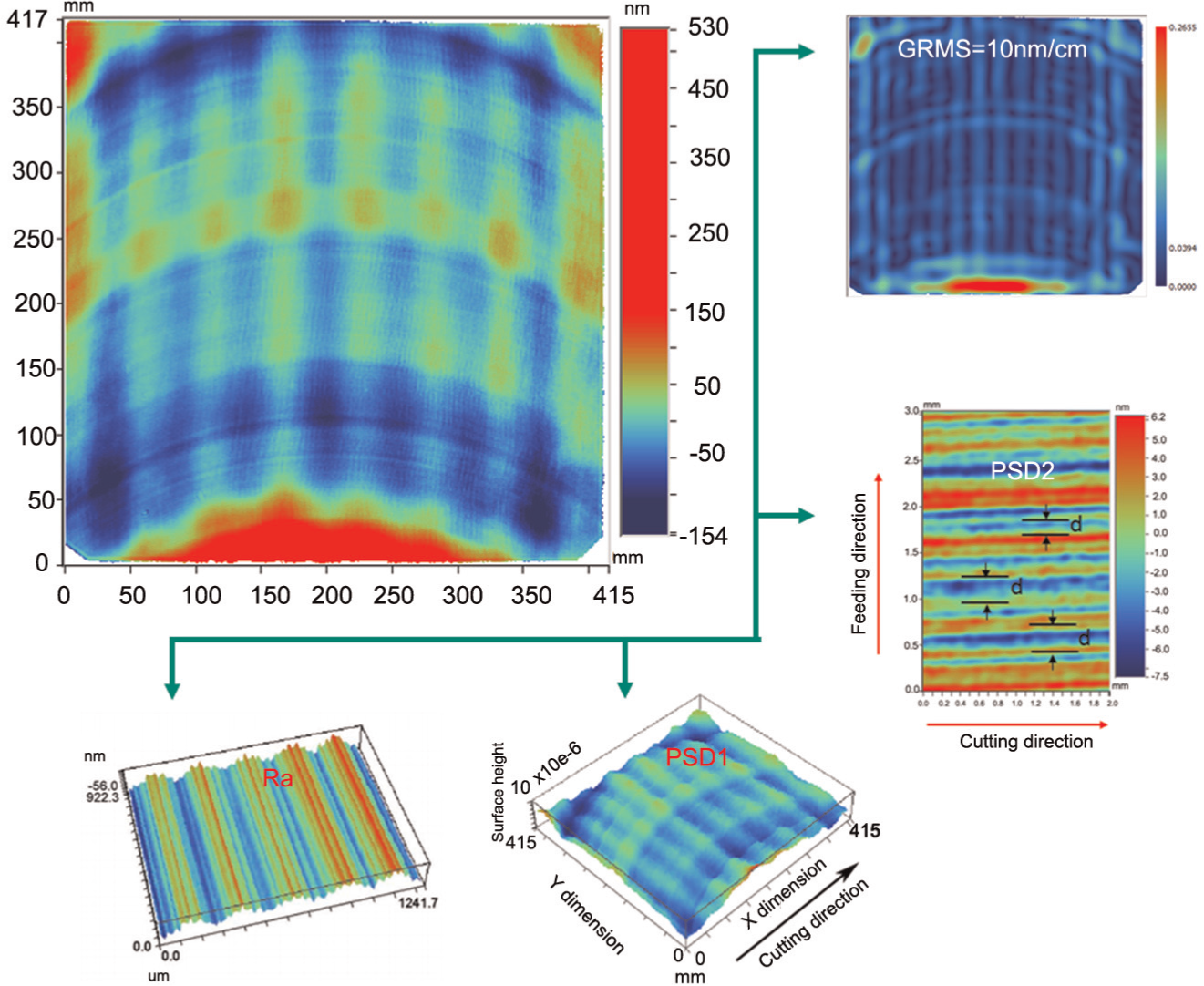
The test result on the machined surface after first round.
The second-round design
PSD1 analysis and machine tool optimization
As shown in Figure 10, PSD1 specification is mainly affected by the waviness on the machined surface. In order to obtain the influence of the machine tool dynamic performance on the machined surface, an accurate FE model is built for the machine tool designed in Figure 11. The input is the periodically interrupted cutting force and the output is the vibration of the tool which will form the waviness on the surface. The relationship between the period of waviness and dynamic performance can be expressed by equation (4)
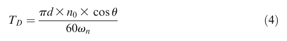
where d denotes the diameter of the flying head (d = 630 mm), n0 denotes the speed of spindle (n0 = 300 r/m),
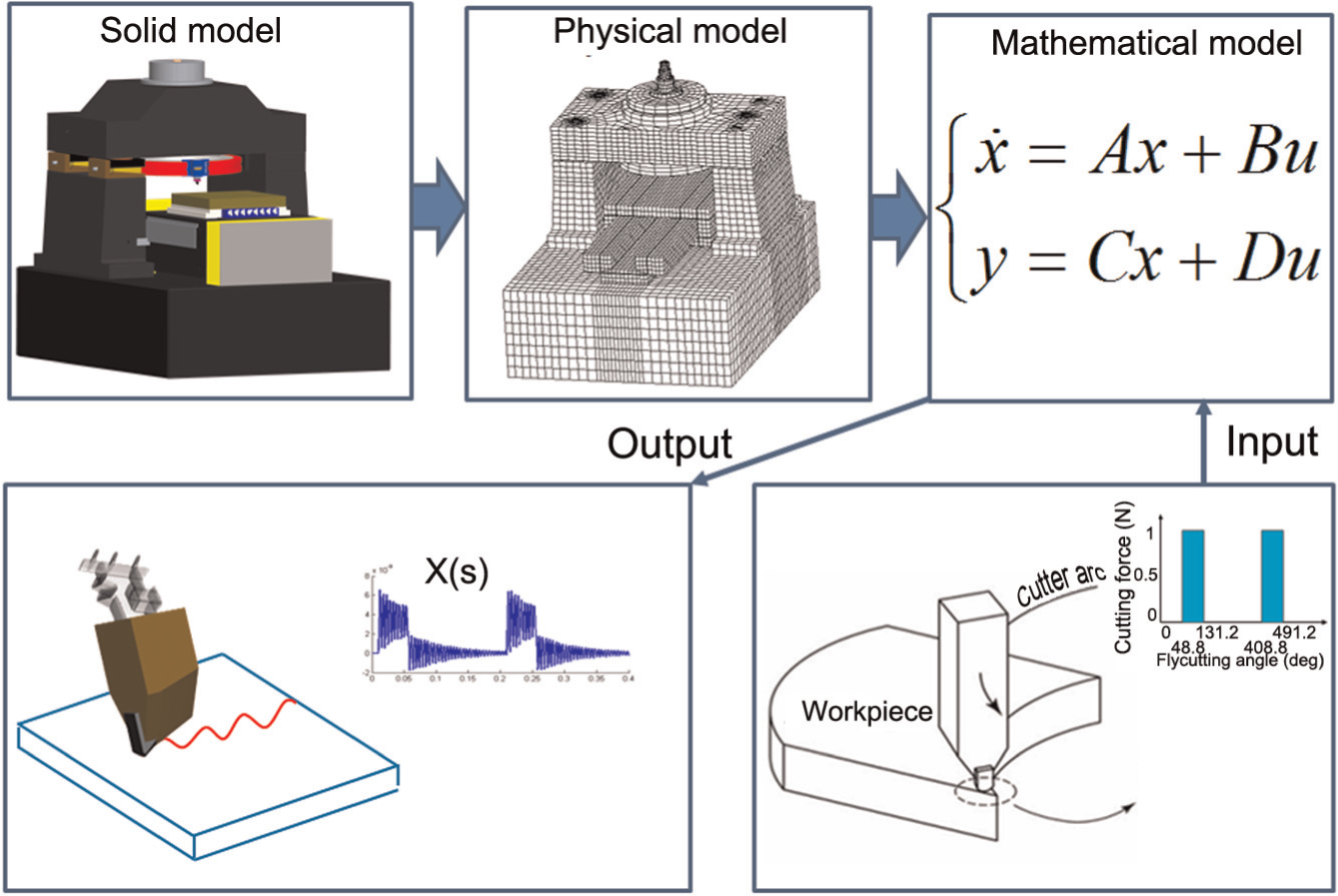
The influence of the machine tool dynamic performance on the machining surface.
From the dynamic performance of the machine tool, as shown in Figure 4, it can be noted that at the frequency range close to the natural frequency of the machine tool, the dynamic stiffness decreases largely, which leads to an increase in the relative displacement between the cutting tool and the workpiece, resulting in the waviness along the cutting direction. 28
The output in Figure 11 shows the integral relative displacement between the cutting tool and the workpiece under the periodically interrupted cutting force, and the relative displacement between the cutter tool and the workpiece caused by the natural frequency pointed in the dynamic response. The response under the high-level natural frequencies has short wavelength smaller than 33 mm with small amplitude, which will affect the PSD1.
Figure 12(a) shows the influence of the high-level frequency of the machine tool on the PSD1. In order to get the PSD1 target, the band pass filter is used, the high-pass frequency is 0.4 mm−1 and the low-pass frequency is 0.0303 mm−1. It shows that the wavelength not in the PSD1 evaluation interval has slight impact on the PSD1. In the PSD1 evaluation interval, the PSD1 is mainly affected by the amplitude of the waviness, and the PSD1 value is increasing with an increase in waviness amplitude. And the wavelength has slight impact on the PSD1. Taking into account the large evaluation interval from 300 to 4000 Hz, it is difficult to avoid the high-level frequency of the machine tool in this region, and in the evaluation interval, the frequency has slight impact on the PSD1; therefore, in the machine design process, there is no significance of optimizing the high-level frequency of the machine tool, but the full account of the amplitude of the dynamic response should be taken. Figure 12(b) shows that to satisfy the PSD1, the maximum amplitude should be less than 17 nm.
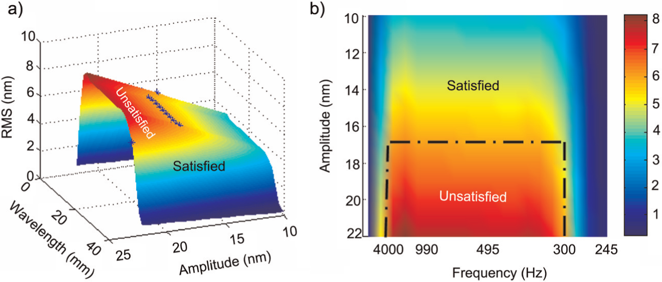
The impact of the dynamic performance of the machine tool on PSD1. a) impact of the wavelength; b) impact of the frequency.
PSD2 analysis and machine tool optimization
An et al. 29 studied the reason of the medium-frequency waviness errors of workpiece surface in flycutting machining which affect PSD2 and pointed out that the waviness was caused by tilting motions of spindle. Furthermore, the 3D locus of the diamond cutting tool is given as follows
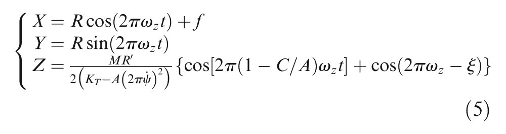
where
From equation (5), it can be noted that the periods and amplitudes of waviness are mainly affected by
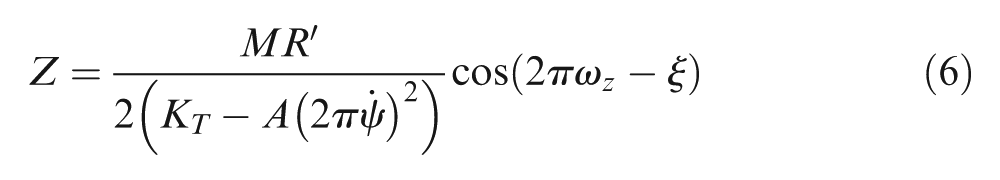
From equation (6), it can be noted that the angular stiffness of spindle KT also has an important influence on the tool tip displacement in the Z direction. A larger angular stiffness of the spindle can reduce the tool tip displacement effectively. Then the structure of the spindle is changed from Figure 13(a) to (b), the aerostatic bearing with a large support surface is adopted, the angular stiffness of the spindle is improved from 635 to 1167.5 N m/arcsec and the ratio of the axial inertia tensor to the radial inertia tensor changed from 0.6 to 1. 30
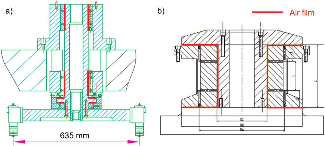
The structure improvement of the spindle. a) initial design; b) optimized design.
The machine tool after the second-round design and the machined results.
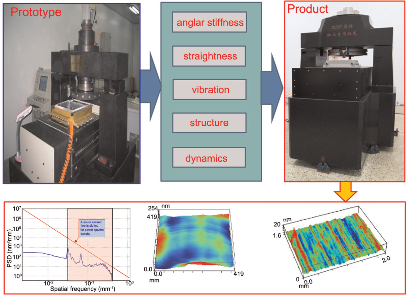
The optimized machine tool and experiments
After the second-round design, the principal factors influencing the PSD specifications are found, and by optimizing the structure of the spindle and the dynamic performance of the machine tool, the final product is built. The test results of the final product show that the GRMS of the machined surface is 0.017 wv/cm (10.76 nm/cm), the PSD1 and PSD2 are below the not-to-exceed line, and the roughness of the final surface is 2 nm. The test results provide the evidence of the second-round design approach being helpful to design the ultra-precision machine tool for achieving strict processing requirements.
Conclusion
In order to achieve the KDP crystal machining, the ultra-precision flycutting machine is designed and improved in recent years, and this article shows a second-round design approach and a review of the design process and method of this machine tool. The following conclusions can be drawn:
A two-round design approach is apposed; it starts from the existed experience, and by combining simulation and experiments, the ultra-precision machine tool design with complex function is realized.
With the comprehensive consideration of the machining parameters and the performance of the machine tool, the gap between the surface topography generation and the machine tool performance is bridged, which helps the designer to determine the design specifications of the machine tool.
The influences of the slide straightness and the machining parameters on the machining result are discussed in the design stage, which provided the theoretical basis for the prototype design.
The influence of the mechanical structure on the machined surface is analyzed. The PSD2 specification is improved by optimizing the spindle structure, which provides a benchmark and guiding significance for the KDP machine tool design.
These experimental tests evaluate and validate that the proposed simulation approach is effective and efficient in machine tool design. It indicates that the proposed design approach can be used as a powerful tool for the machine tool performance and machining parameters optimization.
Footnotes
Declaration of conflicting interests
The authors declare that there is no conflict of interest.
Funding
This study was financially supported by the National Science and Technology Special Program (grant number 2011ZX04004-041), The Sino-UK Higher Education Research Partnership for PhD Studies program, and China Scholarship Council (CSC).