
Abstract
Distinguished with the traditional tooth flank of spiral bevel gears, an accurate spherical involute tooth profile is of obvious advantages for the design and manufacture. For obtaining the gear model with enough tooth flank accuracy, simulation and optimization methodologies of computer numerical control-milling model are proposed. Initially, it gives an identification of the spherical involute tooth flank based on an improved formation theory. A universal simulation machining of the universal multi-axis computer numerical control-milling center is proposed to obtain an initial model. Then, in order to get/for getting improved tooth flank accuracy of the initial gear model, it presents some optimization methods included in the applications which are (1) non-uniform rational B-spline reconstruction by the Skinning method and (2) an overall interpolation based on Energy method. Finally, some given numerical examples are utilized to verify the form error of tooth flank. In addition, a closed-loop experiment scheme is provided to verify the validity of proposed methods.
Keywords
Introduction
In the widespread applications of modern mechanical industry, spiral bevel gear has become an increasingly important transmission component between intersecting axes. Recently, the Gleason PHOENIX® Series five-axis computerized numerical control (CNC) generators equipped with advanced manufacture expert system (GEMS) has been representing the latest and highest level of process technology. 1 However, their designed and processed gears, based on the theory of gearing and all kinds of machining methods, have an tooth profile which is always the approximate spherical involute.2,3 Moreover, it is worth noting that in actual transmission of spiral bevel gear drives, tooth profile existed on the spherical flank whose center is the base cone vertex. 4 That is to say, the accurate tooth profile curve is to be a spherical involute curve. Simultaneously, it has many advantages as the result of a constant transmission ratio by comparing with the conventional approximate one in previous studies, as follows:
In the design, it can obtain the functional expression of the tooth flank equation and a fast and accurate parametric model, mainly due to the numerous and complex derivations with respect to the coordinate transformation and contact property.5–7
In the process, it can maintain the correct state of gear meshing and a constant instantaneous transmission ratio. As a result, it will avoid the influences of noise, heat deformation, uneven distribution of contact pressure and other phenomena. Moreover, it can reduce the application of some vital methods which are employed to reduce above influences in process such as tooth contact analysis (TCA) or loaded tooth contact analysis (LTCA) and tooth flank modification.8,9
With the development of state-of-the-art CNC process technology, there are always several gear researchers continuing advancing research on the spherical involute tooth flank. Shunmugam et al. 10 introduced the exact spherical involute of spiral bevel gear and investigated the normal deviation between the designed tooth flank and the idealized one. Suh et al.11,12 and Daccak et al. 13 carried out modeling and machining methods for the spherical involute tooth flanks. In the Giorgio and Jorge, 14 the exact spherical involute tooth profile of bevel gears and their crown rack are obtained through the pure-rolling motion of a great circle of the fundamental sphere on the base cone. Meanwhile, Zhang et al. 15 and Hu et al. 16 proposed a new process method named Generating-line Cutting Method and some relevant experiments. Li et al. 17 established a mathematical model of spherical involute tooth flank of spiral bevel gear whose generating curve is a circle arc. And then, he got the tooth contact pattern by TCA.
With the promotion of process quality requirements, simulation and optimization based on the actual process has become a mainstream in design and manufacture. The simulation can not only complete fast modeling by making relative motion between the tool and the gear blank, 18 but also greatly reduce workload of the trial-and-error approach in the actual manufacturing as well as get accurate modification parameter. In the current applications, as the approximate tooth profile is so complex, the spiral bevel gear has to be processed only by dedicated machine tools. For instance, as for the well-known Gleason gear system, the special CNC machine tools are divided into two categories named mechanical generator (e.g. NO.116) and multi-axis CNC-milling generator (e.g. PHOENIX Series). 19 At present, machining simulation is mainly based on the Gleason special machine tools. However, such method has some defects, as follows:
The process is too complicated to get high efficiency. Because of too many process parameters in repeated modification and inspection, and calculations of the conversion with multiple motion coordinate systems and nonlinear equations,20–22 it involves a lot of tedious kinematics derivations and all kinds of numerical process methods.
Machine kinematics control is too difficult to ensure the manufacture accuracy. From the microscopic point of view, it needs to employ a serial of complex procedures to execute the position and orientation step by step at each real time status.23,24 because of lacking of the corresponding machine tools and process application software in some existing NC simulation platforms.
Cutting style is too single to get a good validity. In recent simulation, the fundament point is just to make Boolean cutting operations between the cutter and the work blank with a simple kinematics control. Moreover, it can just do carry out the single indexing process based on the mechanical processing machine tool, 25 and the continuous indexing process which is also very important has been rarely mentioned.
However, if the process simulation is based on the universal CNC-milling machining center, it will get an access to breakthrough some bondages of the dedicated machine tools as described above. Additionally, it will greatly reduce the production cost. Especially, it is a very appropriate approach for machining the spiral bevel gears with large modulus and size beyond the general technical specifications. Regarding detailed descriptions, Suh et al.,12,26 Tsai and Hsu 27 and Alves et al. 28 have made some special studies and got some results.
In the present article, distinguished with a traditional fundamental design theory for the spiral bevel gear, a spherical involute theory is improved to indentify a kind of new spherical involute tooth profile. Additionally, considering the university of CNC-milling model, the simulation machining schema based on the universal CNC machine tool29,30 is accomplished. However, the gear model after simulation process has a very obvious problem that its tooth flank accuracy is too low to provide a base model for the follow-up gear analysis, such as TCA, LTCA and tooth flank modification.31,32 Therefore, an optimization solution to the problem is presented by combining the unique advantages with the characteristics in computer aided design CAD/computer aided manufacturing CAM. Apparently, the non-uniform rational B-spline (NURBS) curve and surface fitting method as a main mathematical method for indentifying the shape of product is always of an excellent overall smooth function of curve fitting and local regulation characteristics in ISO STEP standards promulgated. 33 With the extraction of proper data points by the anti-calculation of equation of the cubic NURBS curve fitting, the NURBS construction by the Skinning method is achieved and tooth flank precision of CNC-milling model is improved. Most importantly, overall interpolation based on Energy method for NURBS tooth flank is proposed to obtain the higher tooth flank accuracy. And a practical experimental application is utilized to verify the validity of proposed methodology.
New tooth flank and formation theory
In the present article, the geometry of new tooth profile is more complex than the traditional one and its formation is the application of the spherical involute theory. In previous design for the spiral bevel gear, the fillet tooth flank is often ignored.10,17 In addition, in relevant researches on the spherical involute tooth profile, the most vital generating line is replaced by a straight line.15,16,28 In fact, it just can form the straight bevel gear not the accurate spiral bevel gear. Therefore, considering some drawbacks in previous researches, this article first provides an identification of the spherical involute tooth flank based on an improved formation theory. Then, it makes derivation of the generating line which determines the initial points of whole formation process. As for the parametric modeling process of tooth flank, it is similar with the relevant methodologies in Li et al. 17 and Noh and Hyoung. 34
Identification of the spherical involute tooth flank
This kind of spherical involute tooth flank of the spiral bevel gear differs from the traditional design. Wherein, it contains a top surface, two tooth flanks and two ends, as shown in Figure 1. The tooth top surface is surrounded by the two pieces of top line and the top circle of toe and heel. The tooth flank, namely concave or convex side in symmetrical shape, contains three parts named work tooth surface, tooth root surface and fillet curve surface. Two ends involve the toe and the heel, whose integral tooth profile includes tooth top arc, working tooth profile, fillet curve and tooth root. However, the spherical involute tooth surface is only enclosed by working tooth surfaces including the work tooth profile of the toe and heel, tooth fillet curve and tooth top arc. It is obvious that the work tooth surface is a piece of the spherical involute tooth flank. In the modeling, it is worthy noting that the parametric equation of the work tooth surface is obtained by utilizing formation theory in rest of the article, and the parametric equation of other parts, tooth root surface and fillet curve surface, are consistent with the traditional ones based on the meshing principle and detailed process methods.2,3
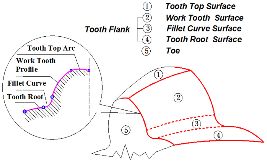
Composition of spherical involute tooth flank.
Formation theory of spherical involute tooth flank
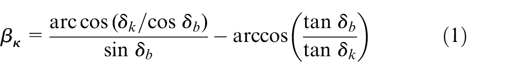
Theoretically, tooth profile curve is the spherical curve in the transmission of spiral bevel gear drives. 5 A ruled spherical involute tooth profile can be not only designed but also processed with a achieved standardization of the tooth profile. Here, the formation theory of spherical involute tooth flank can be described as: the spherical involute tooth flank is the envelope to the tooth profile from one transverse flank to another one. As demonstrated in Figure 2(a), when one plane is purely rolling on cone flank, this flat trajectory of a point on the plane is called the spherical involute. Conical flank is base cone Ok0O1 which is tangent with the circle plane O at the bus bar Ok0. As represented in Figure 2(b), the curve K0Kt in both the plane O and the base circle cone is named as generating line. After taking some equal division points kn (n = 0, 1,…, t) at the generating line, the point kn = 0 should complete motion trajectory to get a tooth profile curve by rotating angle θ. And then, when straight line Ok0, the tangential line when purely rolling, automatically turns a certain angle θn, the next point kn = 1 continually makes a space sphere movement to form a piece of spherical involute tooth profile again. Each point needs to complete a space motion when taking related point from starting point k0 to the end point kt. All of the trajectory curves constitute a whole tooth flank. Besides, this theory can also be described as: changing the radius R of the circle plane named the tangent line by a certain angle θn, its transverse point kn (n = 0, 1,…, t) makes the completion of once space trajectory; finally, all the trajectory curves are evolved the spherical involute tooth flank. The equation of the spherical involute K0Kt can be expressed by the spherical deflection angle βk at any point K, as follows 34
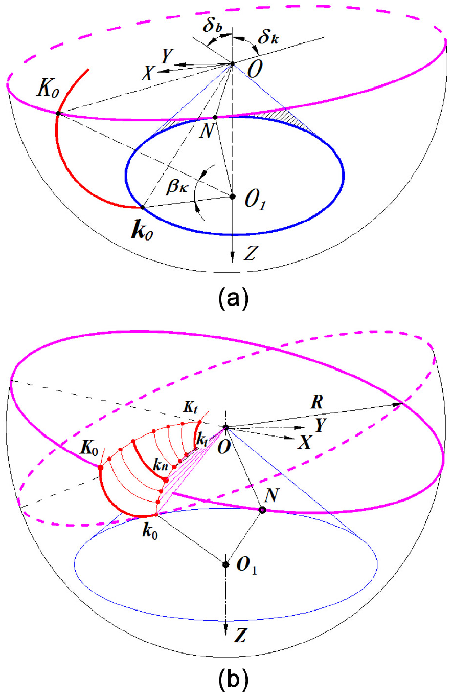
(a) Formation of spherical involute and (b) formation of spherical involute tooth flank
In the established spherical coordinate system (see Figure 2), the spherical involute can be expressed as

where δk is cone angle at a point of the corresponding spherical involute, the ρ = Rk ∈ [R-B, R], θ = δk ∈ [δf, δa], where B is face width, δa is top cone angle, δf is root cone angle and δb is base cone angle. They are the basic geometric parameters.
In the formation theory of spherical involute tooth flank, the numerical expression to the generating line k0kt and the initial motion points are the keys to the formation of the tooth flank. Considering tooth flank characteristics of the spiral bevel gear, generating line can be presented by a certain mathematical function based on the base cone spiral curve which is an Archimedean spiral curve named equidistant spiral curve. And then, the function of base cone spiral cure is represented in Figure 3(a)

where βn represents spiral angle at any point on the toe and heel. It can be obtained by following formula 4

where rc means the radius of the cutter head, Rn indicates cutter location and Rp signifies the cone distance in correspondence with nominal spiral angle β.
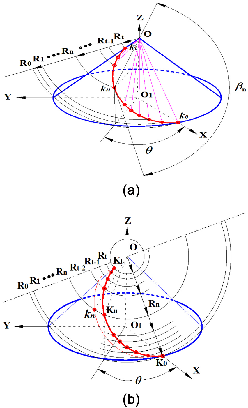
(a) Solution of the generating line and (b) determination of the initial points.
Finally, as shown in Figure 3(b), base cone apex O as the ball center is made a serial of variable radius ball to not only intersect with the spiral lines at one point kn but also with the circular flank intersect at one point Kn, and the last intersection points can constitute the initial movement points.
Simulation CNC-milling modeling
Recently, the tooth flank of spiral bevel gear is required a high precision. In the actual manufacture, it needs dedicated machine tools to complete the complex machining through repeated trial-to-error process to determine the target modification machine settings. For obtaining sufficient precision, it generally exploits many processes such as the milling, heat process and grinding with the special machine tool and so on. After machining, it will employ the TCA, LTCA, tooth flank modification and so on to make modification and verification of the machine settings.17,28 However, due to so complex process technology, 35 many related sets of equipment that can execute precision process are in the technological blockade and monopoly and often depended on import, so that it greatly increases the cost of production. In addition, there is a very obvious limitation on the dedicated machine that its process is limited to a certain size range, such as the maximum machining diameter of Gleason gear system is about 1000 mm. It is not suitable to satisfy the demand of the small batch, big modulus and big size gear in modern industry such as the coal machinery and ship machinery. Whereas, the universal five-axis machining center can overcome the defect, breakthrough these limitations and especially create the conditions for spiral bevel gear production in the small batch or super-size, because of not high tooth accuracy requirement.
Procedure of simulation CNC-milling
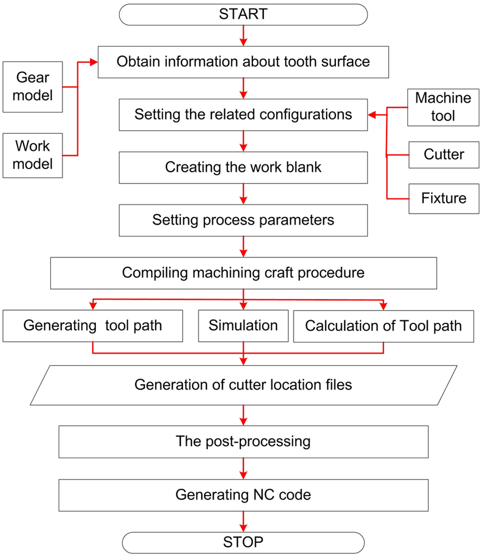
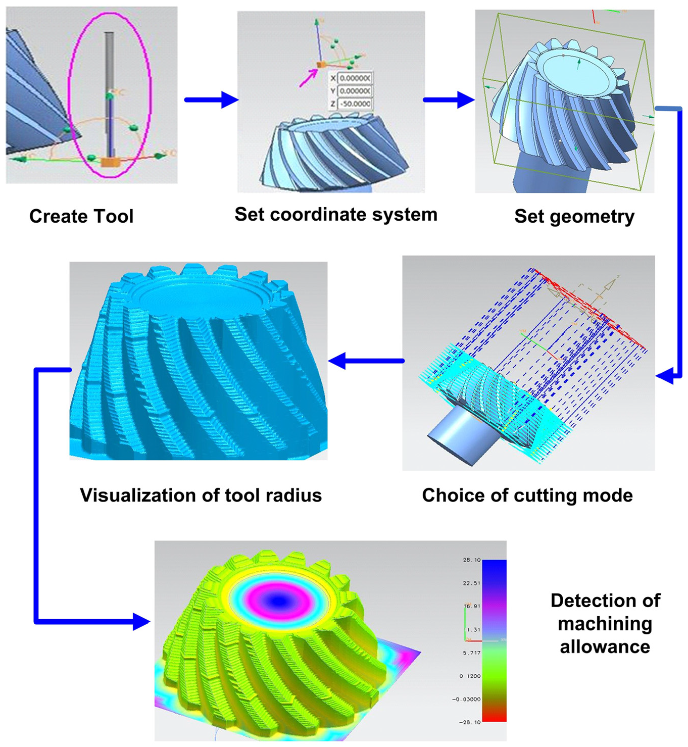
Figure 4 shows the general process of milling machining on the platform as Pro/E software. Generally, it contains some basic parts, as follows:
Getting basic information about tooth flank. It is foremost to obtain the basic model and identify the basic geometric shape of working gear to be machined. Here, the basic geometric shape is obtained by parametric modeling from equations of the spherical involute tooth flank based on the improved formation theory. 17
Setting related configurations. It mainly includes the choices of simulation software platform (such as Pro/E, UG, CATIA), machine tool, fixture, cutter and NC simulation system. In general, a five-axis linkage machine tool is selected, and the cutter and fixture should be to select in the view of the CAPP and the quality requirement of the actual machining. For example, this article chooses the Fagor CNC 8055/B-GP four-axis linkage CNC system with the seven-axis machine tools.
Creating work blank model. It generally contains the material and the size and is achieved by parametric modeling based on basic geometric parameters.
Setting processing parameters. There are some parameters about cutting machine tool, cutting feed speed, feed amount, spindle rotation speed and the amount of backing, which should be set on the basis of production demands and among which the most important is the machine chine settings which are utilized for tooth form error modification.
Pre-processing. It contains the compiling of the machining craft procedure, generation of the tool path, and the simulation and calculation of the tool path.
Post-processing. It means that the tool paths are transformed into the movement tracks with the following formula to complete machining by generating NC codes
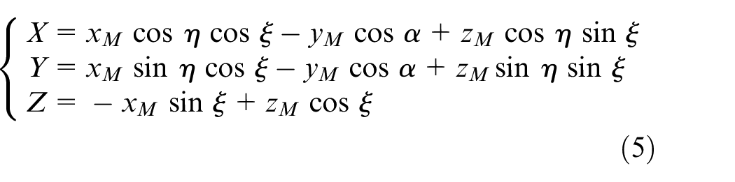
Here, it selects a five-axis machining center which includes three mobile axes X, Y, Z axes and two rotation B-axis, C-axis, where the Y axis is parallel to center line of B-axis, and C-axis is parallel to center line of Z-axis. Therefore, with the above formula, the cutter location coordinates of point M are presented as (xM, yM, zM), C-axis rotation angle is η, B-axis rotation angle is ξ and the movement coordinate of machine is (X, Y, Z).
General process of CNC-milling simulation.
In this simulation, the vital step is the compiling machining process procedure. First, it is turning of the forging gear blank, the milling of tooth slots and flanks and then grinding of the gear tooth flanks. Finally, it needs to make inspection and adjustment for the grinding gear contact area in order to improve the quality of tooth flank process. Whereas, the most significant part in the whole process is the milling part. It can be divided into three processes: rough machining of tooth slot, vice-finishing and then finishing of tooth flank. Figure 5 represents the general process of the rough machining of the slot. Additionally, the simulation process of the gear is similar to the pinion, but its finishing is simpler.
General process of pinion rough CNC-milling.
Accuracy analysis of tooth flank after simulation
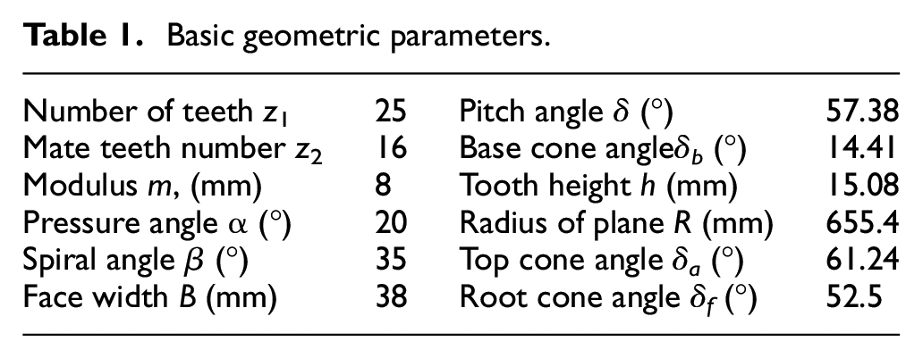
This article provides an initial gear model of spiral bevel gear whose basic geometric parameters are represented in Table 1. It is outputted from the simulation process based on the universal machine milling center, as indicated in Figure 6. Distribution of tool trace on the tooth flank from the toe to the heel is varied from the dense to sparse, in which the greater the density is, the larger the deviation is. An observation of the initial model of the simulation process indicates that the tooth form error accuracy is very poor. The tooth flank is full of so many clear and visible tool traces, even with some modifications of the different tools, the feed rates, the cutting speeds and other conditions. Especially at the fillet area, rugged tool traces with different patterns can keep mutual overlap to make it worse. And at the root area, the tool trace distribution is too few and scattered. In fact, this simulation is enveloping generation procedure of every cutting trace and is implemented by the Boolean substrate operations between cutter head and blank. 19 Consequently, the control accuracy of the relative motion state is not high enough. It means that existence of obvious trajectories is inevitable, as well as poor tooth flank accuracy.
Basic geometric parameters.
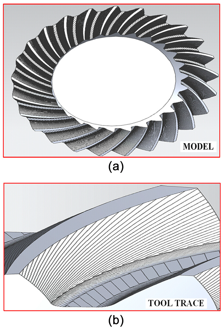
(a) Initial gear model and (b) tool trace distribution.
NURBS reconstruction for the spherical involute tooth flank
In exact line with the advantage of cubic NURBS curves, the tooth profile curve whose each part has different forms can be expressed into a unified and accurate representation with the standard expression of NURBS curve, as well as a unified NURBS surface. Moreover, the cubic NURBS curves and surfaces also have flexible modifiability to achieve a better tooth flank accuracy by adjusting the control points and the weighting factor. Therefore, the cubic NURBS reconstruction by the Skinning method for tooth flank model after the simulation CNC-milling is proposed for good tooth flank accuracy.
Extraction of optimized tooth data points
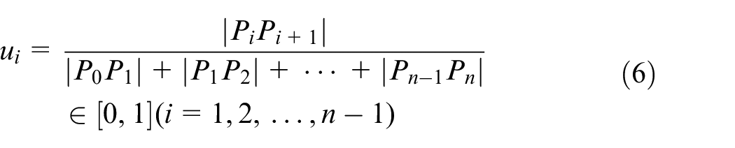
According to tool trace distribution on the CNC-milling model, the intersection points constitute the boundary curves of the tooth flank which can be extracted as the initial data points. With the application of the detailed extraction method, as represented in Figure 7, whole tooth profile part including the work tooth profile, fillet and tooth root portion is selected as an object to make coordinate information of the corresponding selected points. In order to get optimal selection of data points on cubic NURBS curves, it employs a process method as shown in Figure 8. As the fillet process on the tooth profile curve is a key part and its knife pattern becomes denser than other areas, the extraction of the data points need to be larger. Here, the tooth profile is assumed as v-line and the fillet curve is assumed as the u-line. Two lines have same quantity of data points. If the data point Pn in the initial sampling can constitute a curve equation F(u), the corresponding parameter of each point is u and can be obtained by the following formula
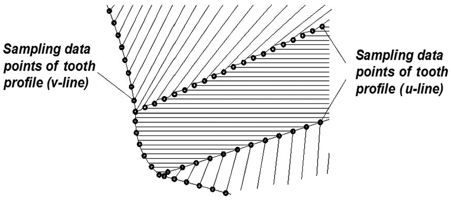
Sampling of initial data points.
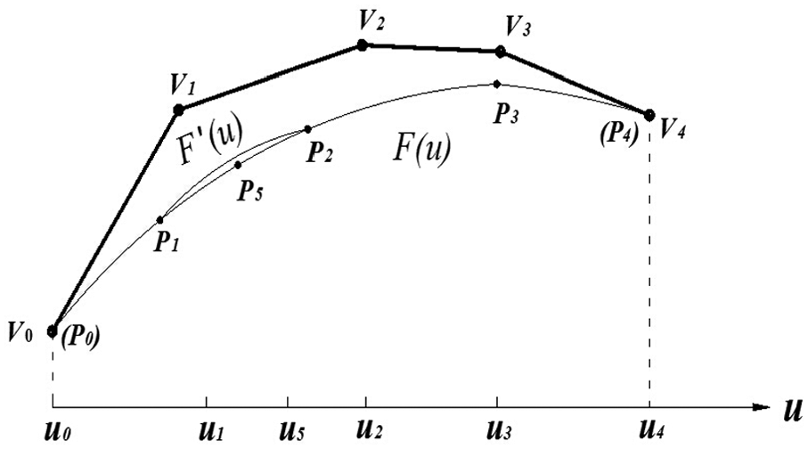
Optimal selection of initial data points.
With application of above method, it can be seen that the number of data points need to be small to ensure sufficient accuracy especially at the free fillet flank. Therefore, it adopts the proper error correction according to the following testing formula
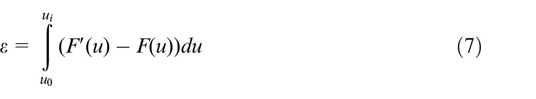
If the error is greater than error ε determined by formula in the fitting process, it needs to be corrected with appropriate interpolation. Wherein, it will insert new parameters to the data points on interval [ut, ut+1] by the calculation formula

Cubic NURBS curve fitting
As motioned above, a unified fitting is utilized to get improved precision because of different shapes and parametric expressions of each part of tooth profile. Apparently, the cubic NURBS curve method is a perfect fit for it. Cubic NURBS curve can be represented as polynomial function of a segmented vector
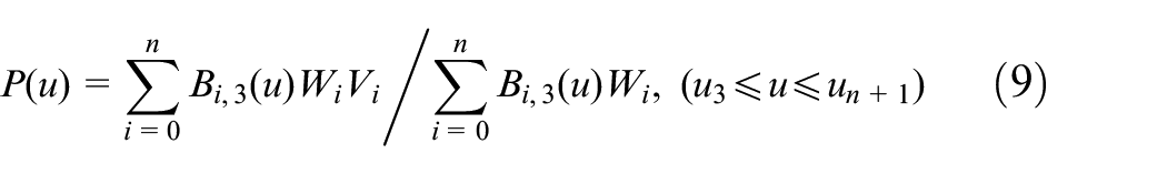
where the gear node vector U = [u0, u1,…, un+3+1] ∈ [0, 1], Vi (i = 0, 1,…, n) represents control vertices, Wi (i = 0, 1,…, n) is weighting factors and Bi,3(u) is the cubic B-spline base function.
Compared with the fillet curve (u-line), the solution to tooth profile (v-line) is more complicated. Therefore, a tooth profile curve on the tooth flank, as an example, is selected to discuss. The fitting of extracted data points of the other curve had similarities and consistency. As shown in Figure 9, it is a general flowchart of the cubic NURBS curve fitting for the selected data points. And, we can obtain as
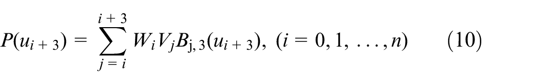
where the above equation can be done to solve the control vertices by combining with known weighting factors in means of flank quality requirement.
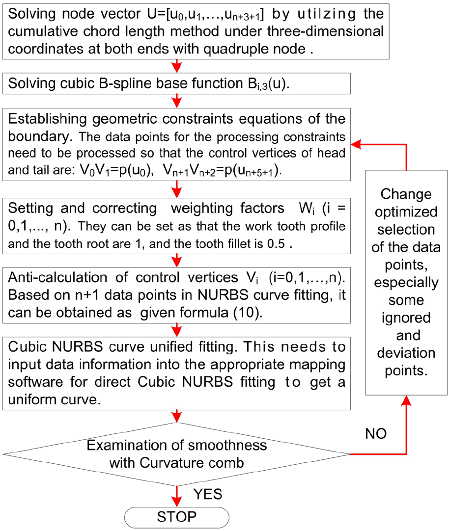
Flowchart of the cubic NURBS curve fitting.
NURBS construction by the Skinning method
Cubic NURBS surface is defined as
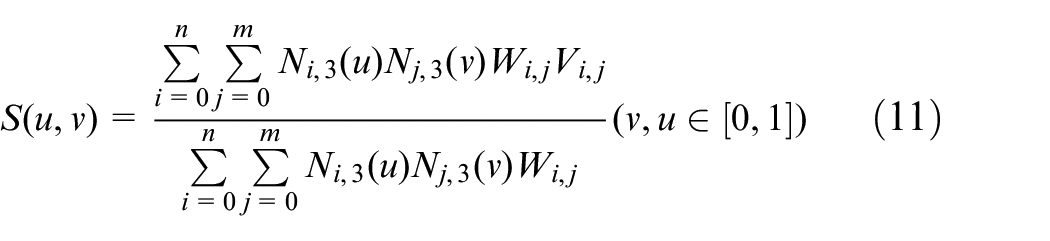
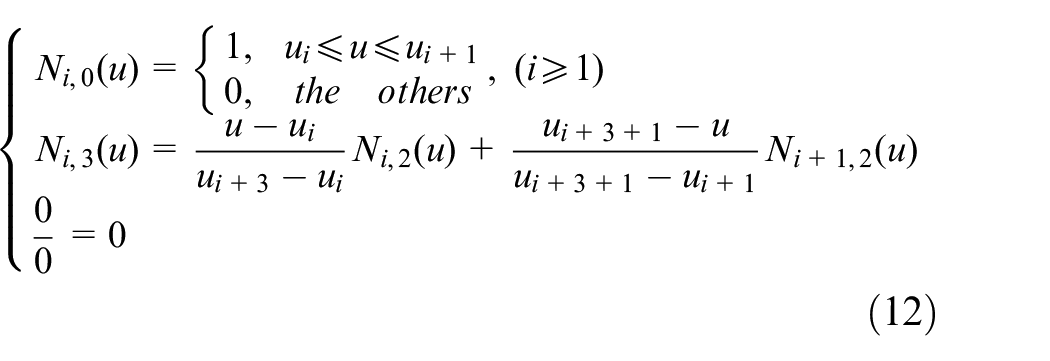
where u, v ∈ [0, 1], Vi,j are the control vertices and Wi,j are the weighting factors. Node vectors at the u-direction are expressed as U = [u0, u1,…, un +3+1] ∈ [0, 1] and calculated by formula (6). Similarly, u-direction ones are consistent with them. Ni,3(u) and Ni,3(v) represent the cubic B-spline base function at u-direction and v-direction, respectively. They can be solved by following DeBoor-Cox formula
In the present article, according to the fitting NURBS curves with optimized extraction of data points, Skinning method 33 was used to construct the NURBS base surface. There are some specific steps, as follows:
Stage 1. Identification of main boundary curves. In simulation CNC-milling, the software-related functions are utilized to extract geometric boundary curves drawn. A tooth flank mainly consists of tooth flank boundary curves such as tooth top curve, tooth profile of toe and heel and tooth root curve.
Stage 2. Construction of the internal cross-section curve family. It needs to take v-line as the section line and select data points of the u-line on the tooth fillet curve as constraints. And then, the cross-section curve family can be constructed by accurate fitting.
Stage 3. Unity of node vectors. Each cross-section curve vector (set as u-direction) is made the operations. An algorithm of insertion mode is proposed to get control vertices of each section curve. Then, a modified radial accumulated chord length parameter method is applied by following formula
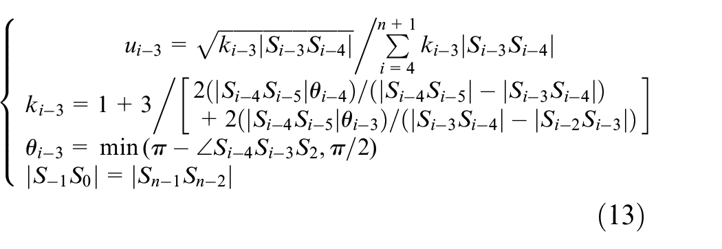
where S presents u-direction node, i = 1, 2,…, n.
Stage 4. Solution of u-direction control vertices. It can take the average value of the unified node vector as their node vector. And then, some solved control points as data points are needed for anti-calculations one by one at u-direction, as denoted on the left-hand side of Figure 10.
Stage 5. Skinning operations. Based on the boundary curves and the internal cross-section curve family after NURBS fitting, all control points are calculated. Then, the Skinning method is employed to construct the NURBS for the whole tooth flank like one side of tooth flank displayed in Figure 10.
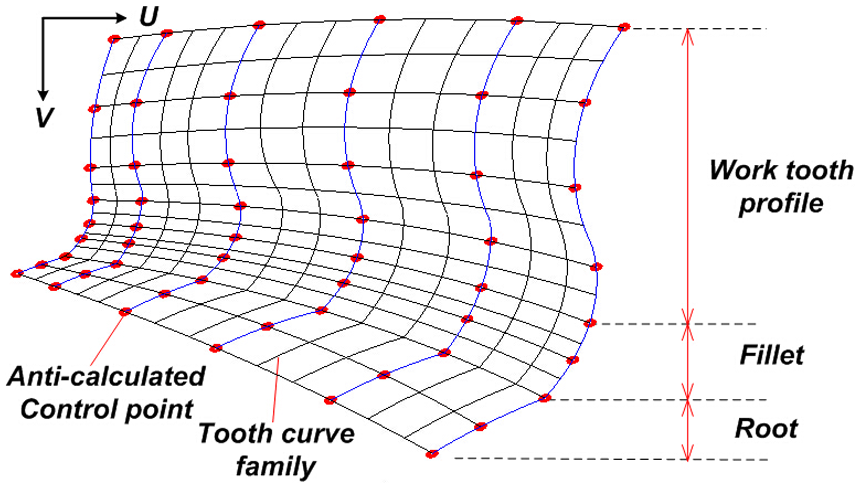
NURBS fitting of tooth flank.
Overall interpolation based on Energy method for NURBS tooth flank
Since the unevenness phenomena of data points on the original tooth flank model after machining simulation, its smoothness is still very poor even after the NURBS reconstruction. Moreover, in the extraction of tooth flank points, there are some uneven or unreasonable, unknown or ignored, which can entail some singularity phenomena about the data points. For obtaining high tooth flank precision, it needs to perform an optimization for the NURBS tooth flank. In this respect, an overall interpolation method of data points based on Energy method is employed.
In this work, it needs an optimization idea to construct an objective function that can present the smallest strain energy of the NURBS base surface in the optimized model. The control point as a variable is utilized to solve the data points at the smallest strain energy position of the basic tooth flank. While the strain energy could be supposed as E(x), unknown data points on the surface are xi ∈ Rh, and the optimized model is presented as
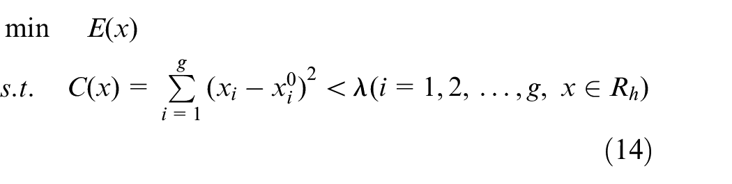
where the objective function
Herein, the strain energy can be represented as 36
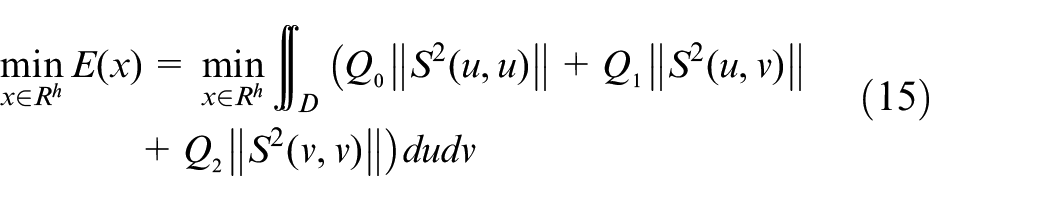
where Q0, Q1, Q2 are the three coefficients of the strain energy on the tooth flank. Combined with some related equations, the above equation can be transformed into a quadratic programming problem and can be solved.
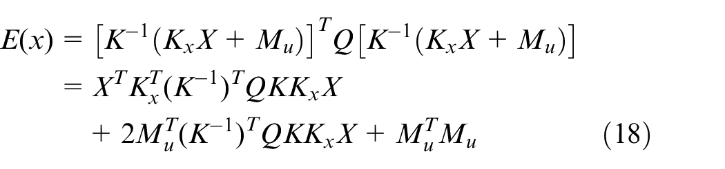
Substituting equation (9) into equation (13), there is

where U is the column vector of control points and Q is coefficient matrix of surface strain energy. Meanwhile, the linear equations can be established as

where M is column vector of ordered value points, Mx is the column vector of unknown data points and Mu is the one of known points. Unknown data points are assumed as X and their coefficient matrix is Kx.
Combining with equations (14) and (15), there is
As this is the quadratic programming problem, so its optimal solution is required to meet

Finally, after setting the condition λ and solving equation (17), a new tooth flank with minimum strain energy is obtained. This article gives a numerical example where the error range is set as λ = 0.01 mm and a developed software platform is used to complete calculation. The tooth flank after optimization is shown in Figure 11. The result shows that new tooth flank has good uniformity and smoothness, and on the fillet area, it also has some obvious changes on strain energy and can be consistent with the actual state.
A new tooth flank after optimization.
Tooth flank form error after optimization
In previous modeling of the spiral bevel gear, the B-spline fitting method for the initial discrete points is one of the most main means of tooth flank construction. It was mentioned by Gabiccini et al and Artoni et al.37,38 Recently, Lin and Fong 39 have conducted a detailed study. After the B-spline fitting with 37 × 33 control points, the normal error range is reduced to 100 µm. As shown in Figure 12, it represents the tooth flank form error on concave side of gear model after the above simulation CNC-milling. With calculations between the initial data points and theoretical points, the average error can reach 264 µm, the maximum error is 348 µm and the minimum is 71.1 µm. The distribution of data points is almost in the messy, unevenness and poor continuity mainly because of the cutting feed speed, the feed amount and sampling error and so on.
Tooth flank form error after simulation.
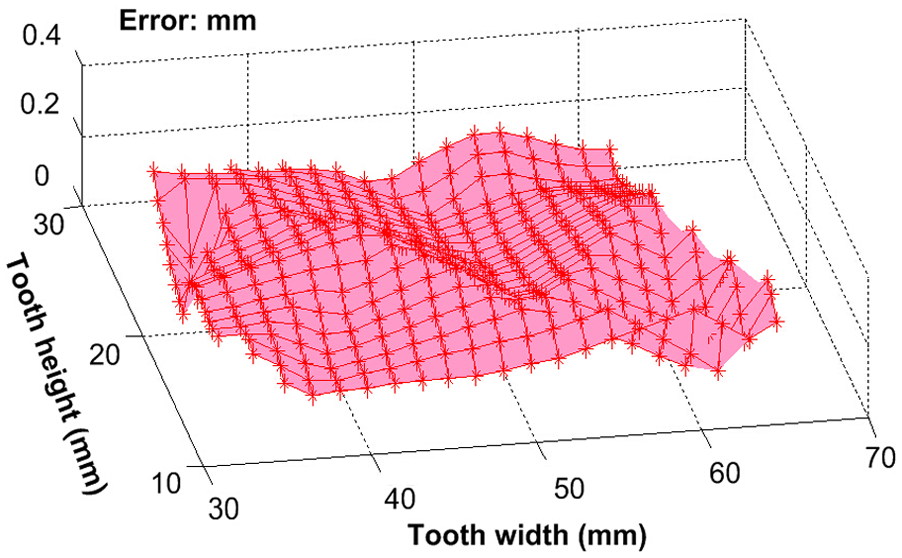
With the NURBS uniform fitting of the spherical involute tooth profile and the entire tooth flank, the residual normal error is obtained, as shown in Figure 13. The average error can reach 74.5 µm, the maximum is 223 µm and the minimum is 23.2 µm. Most of larger error values concentrate on the gear heel. Compared with initial model, the tooth flank error is greatly reduced and its continuity and smoothness are significantly enhanced. In order to get tooth flank form error values of the final gear model after optimization, several uniform discrete points Px(u, v) on the tooth flank after optimization are selected and imported into the solid model for the comparison of their normal error of entire tooth flank with theoretical points P(u, v). The theoretical points are obtained with the calculation from the parametric equation of tooth flank. The error flank δ is represented as difference surface
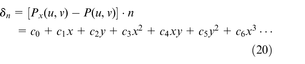
Residual normal error of tooth flank NURBS reconstruction.
For the above error flank, generally, it can be expressed as approximate fitting equation solved based on the least squares method. 37 In above equation, the efficient c0 reflects tooth pitch deviation. The first-order coefficients c1, c2 reflect position deviation about pressure angle and spiral angle error, respectively. The second-order coefficients c3, c4, c5 reflect curvature error. The third-order and other coefficients reflect torsion error and so on. As shown in Figure 14(a), in the polynomial fitting of error flank with 6 × 11 points, x and y are third order, respectively. Thus, the error flank polynomial expression can be represented as
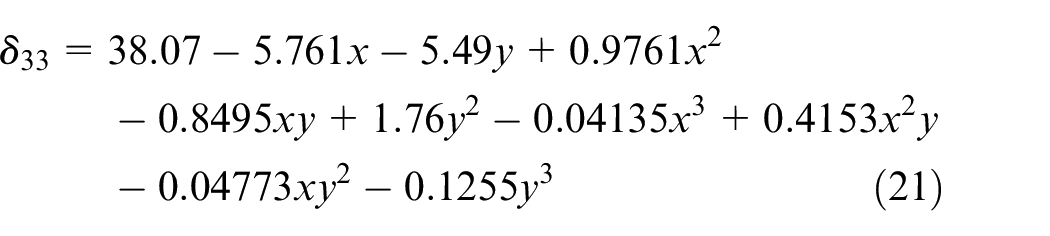
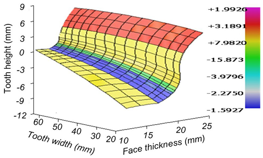
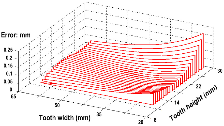
The order of x and y are generally 3 or 4 because of the goodness of fit. In above, the goodness of fit is sum of squares for error (SSE) = 0.000202, R-square = 1, Adjusted R-square = 1 and root mean square error (RMSE) = 0.002595. It can verify that these orders to be set in the fitting have high goodness. With relevant calculation, the maximum absolute value of tooth flank form error on convex is 34.05 µm, the minimum error is 17.05 µm and the (RMSE) is 23.16 µm. Figure 14(b) representing the tooth flank form error distribution is more clear and more accurate than conventional error flank represented by the difference flank.19,30 It can get an access to tooth flank modification with higher accuracy, even just utilizing the modification of certain machine settings. In Shih and Shen, 40 RMSEs before tooth modification based on the universal machine tools are 40.9 µm on concave and 33.8 µm on convex. In Kawasaki and Tsuji, 41 a tooth flank with error 24 µm is applied to TCA. Therefore, this error accuracy can meet the requirement especially for the super-size gear. Meanwhile, it can get an accurate model provided the follow-up studies such as TCA, LTCA and tooth flank modification and so on.
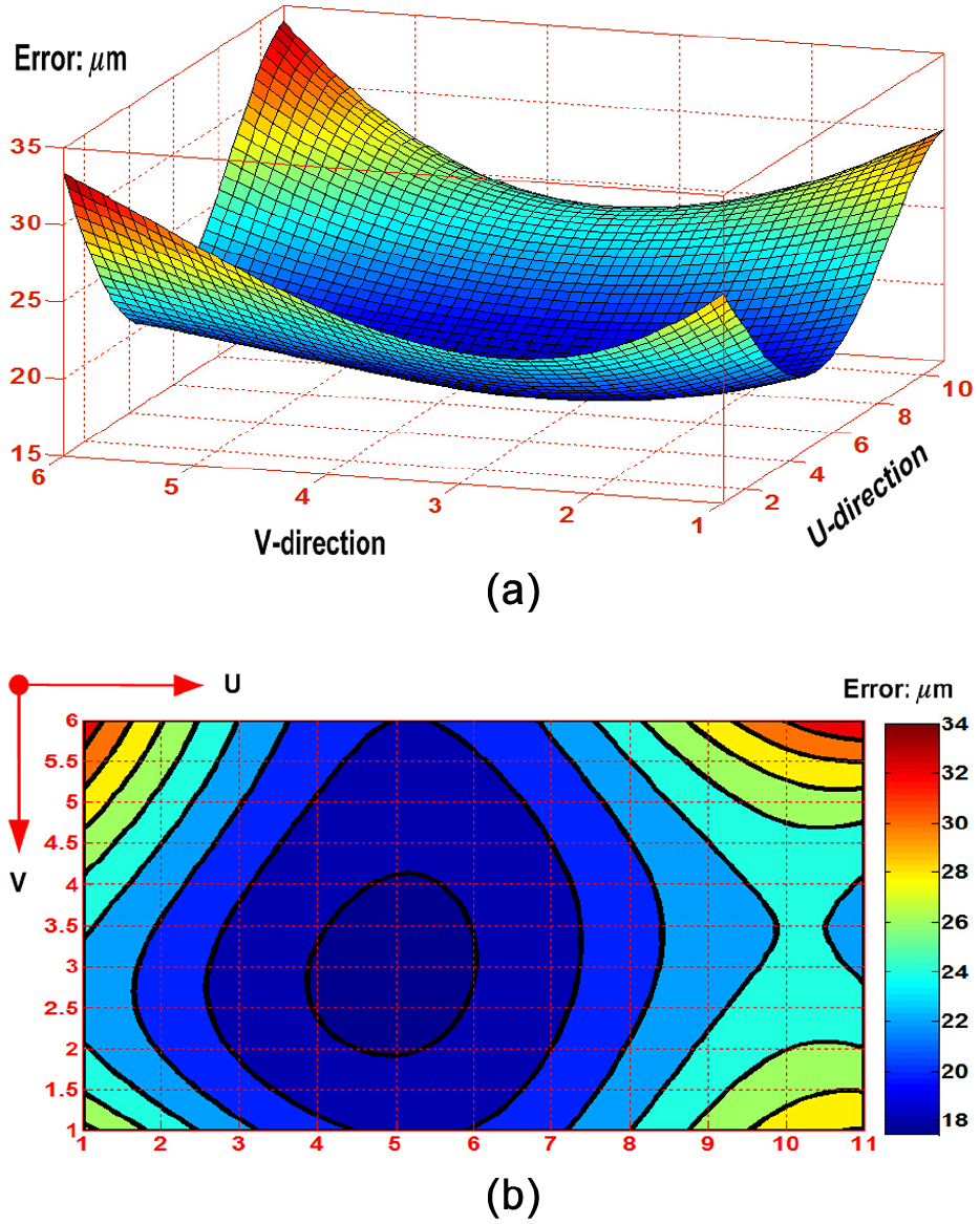
Residual normal absolute error of flank optimization: (a) error flank and (b) error distribution.
Experiment result and discussion
From practical application perspective, the goal of universal simulation CNC-milling based on the universal CNC multi-axis machining center is the NC codes which are applied to universal machine tool to execute actual accurate process. Therefore, this article gives experiment results with application of proposed method. As shown in Figure 15, it is a closed-loop process in actual CNC-milling process. The gear model after final optimization is utilized to get information on the tooth flank in simulation process. Using the generating NC codes, universal CNC-milling machine tool can complete gear machining. And then, the real tooth flank form error in actual process is measured by Coordinate Measuring Machine (CMM). According to universal Gleason standard, 1 the predetermined region containing 80% face width (FW) and 90% tooth height (TH) is discreted by given 5 × 9 points grid which generally takes j = 9 data points along the FW direction and i = 5 data points along TH direction according to the measurement rules. Finally, it is necessary to analysis the tooth flank form error, due to judge whether the error meets requirement or not. If the result does not meet requirement, it needs to make virtual simulation, actual process and tooth flank form error measurement again and again till the result meets requirement. Hence, the entire system is also a closed-loop process. In order to get higher accuracy, an access is to make repeated process based on the error measurement; another access is to obtain a higher precision model using reconstruction and optimization which can support an accurate simulation CNC-milling before actual process.
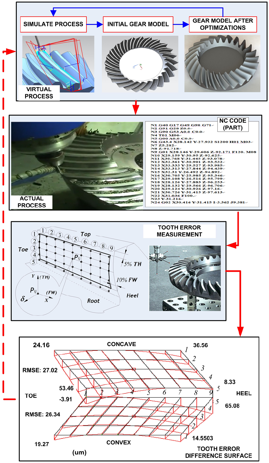
A closed-loop process of CNC-milling experiment.
It can be seen that the maximum tooth flank form error is 53.46 µm on the concave and 65.08 µm on the convex. The RMSEs are 27.02 µm on the concave and 26.34 µm on the convex. On the gear convex, tooth flank form error distribution is concentrated on two ends where most of large errors concentrate on the heel. It is almost consistent with tooth flank form error after relative optimization. Here, on the same convex tooth flank, designed value in proposed methodology is a little less by 12.01% than that RMSE in actual experiment. It is rational because there are all kinds of errors with influence on measurement error results in actual process. And there are some errors including geometry, thermal deformation, tool wear, operation, detection and other errors in the actual process.26,42 At the same process type of spherical involute tooth profile in reference published by Suh et al., 26 the error on one tooth can reach about 30 µm. Meanwhile, the real error can also meet the general requirement. If it did not, a closed-loop process can be made once again for a higher precision.
Recently, a universal generation model (UGM) has been developed into a active topic and can be utilized to tooth flank geometric description of the spiral bevel gear.19,30,37,38 The modification technology of universal machine settings based on UGM is always a main way of topography optimization of tooth flank.43,44 With CNC-milling simulation via the universal machine center, it can also get a good access to higher accuracy manufacture via modification with the machine settings. The above methodologies are of great importance for actual process of spiral bevel gear and hypoid gear, especially to the small batch, large modulus and large size gear.
Conclusion
In the present study, the spiral bevel gear with a new tooth flank is proposed to obtain an accurate model based on simulation CNC-milling. Several distinct features of the proposed methodology are summarized as follows:
A new spherical involute tooth profile based on the improved formation theory is introduced to make parametric expression of tooth flank simpler and more accurate than the traditional method. Meanwhile, the gear drive with this tooth profile has an advantage of easily maintaining a good contact motion state.
Simulation CNC-milling based on CNC multi-axis machining center is employed to get an initial gear model. However, the tooth flank accuracy of CNC-milling model is very poor. The NURBS reconstruction by the Skinning method is proposed to improve accuracy.
For obtainment of optimal tooth flank, the overall interpolation based on Energy method for NURBS tooth flank is utilized to get a tooth flank with good smoothness and accurate tooth flank form error. And a closed-loop experiment exploited to verify the validity of proposed methods.
Footnotes
Declaration of conflicting interests
The author(s) declared no potential conflicts of interest with respect to the research, authorship and/or publication of this article.
Funding
The author(s) disclosed receipt of the following financial support for the research, authorship, and/or publication of this article: This work was supported by the National Basic Research Program of China (2011CB706800) and the National Natural Science Foundation of China (NSFC) (Nos 51275530, 51305462, 51535012).