
Abstract
This article proposes the sine series representation of jerk profile for acceleration/deceleration feedrate scheduling of parametric interpolator used in computer numerical control machining tools. By selecting the geometric sequence as the coefficients of the sine series, the closed-form expressions of the feedrate, acceleration and jerk profiles are obtained. The resulting feedrate profile is more concise compared with the polynomial profile and more efficient compared with the trigonometric profile. It can be well accepted by the conventional acceleration/deceleration feedrate scheduling algorithms. Also, an approach is proposed to determine the optimal geometric sequence that makes the tracking time as small as possible. Simulations and experiments of tracking complex contours expressed as free-form non-uniform rational B-spline curves are conducted. The results demonstrate the effectiveness of the proposed feedrate profile and the resulting feedrate scheduling strategy.
Keywords
Introduction
The feedrate scheduling, which determines the smoothness, accuracy and stability of the machining process, is one of the most important factors in the interpolation of parametric curves. In order to achieve high-speed and high-accuracy machining, various techniques for feedrate scheduling of industrial robots and computer numerical control (CNC) machining tools have been proposed for both the linear and parametric tool paths. The existing feedrate scheduling algorithm for parametric tool paths can be roughly divided into two broad families of classes: the acceleration/deceleration (AD) approach and the time-optimal (TO) approach.
The TO approach was first applied to solve the minimal time control problem for robotic actuators, and the shape of a feedrate profile is not known in advance but determined by some differential equations. 1 This approach can be further classified into two categories: the numerical methods2–7 and the analytic methods.8,9 Dong and colleagues2,3 and Beudaert et al. 4 proposed two similarly practicable methods to handle the feedrate scheduling problem numerically by solving a series of constrained optimization sub-problems. Zhang et al.8,9 proposed an analytic way towards this problem by searching the intersections of the so-called velocity limiting curves/surfaces deduced from the acceleration, jerk and chord error constraints. Although optimal, these methods cannot guarantee a feasible solution even after an intensive computation.1,10 Moreover, the numerical off-line optimization method generally needs a re-interpolation process to obtain the feedrate values at each interpolation period, which may cause undesirable errors. The analytic methods can only be applied to simple parametric curves due to the requirement of solving differential equations. Recently, Sun et al.11–13 proposed a novel adaptive feedrate scheduling method that considers drive constraints. A B-spline curve was adopted to represent the feedrate profile, and its control points were adjusted iteratively, leading to a near-optimal feedrate profile under the prescribed constraints. The re-interpolation was still involved in this method.
The AD approach was first applied to line segments14,15 which are the most widespread representation for tool path in CNC machining. Detailed and nice work on how to generate a universal AD velocity profile for line segments was given in Jeon and Ha 16 and Luo et al. 17 Later, this method was extended to deal with parametric tool path.18–24 As mentioned in Fan et al. 10 and Luo et al., 17 the most widely used profiles in AD approach are polynomial (e.g. linear-velocity, trapezoidal-velocity and trapezoidal-acceleration) and trigonometric profiles. With the polynomial profile, the process of the feedrate scheduling becomes complicated and the expression of the profile becomes cumbersome for a smoother profile. A piecewise velocity function with seven sub-functions 25 was needed to describe an acceleration phase with trapezoidal jerk as illustrated in Figure 1(a). Moreover, four kinds of acceleration profiles were developed for different conditions.14,23,26 With the trigonometric profile, the machining becomes less efficient because only one point can reach the given maximum value of the acceleration or jerk profile, 22 as illustrated in Figure 1(b).
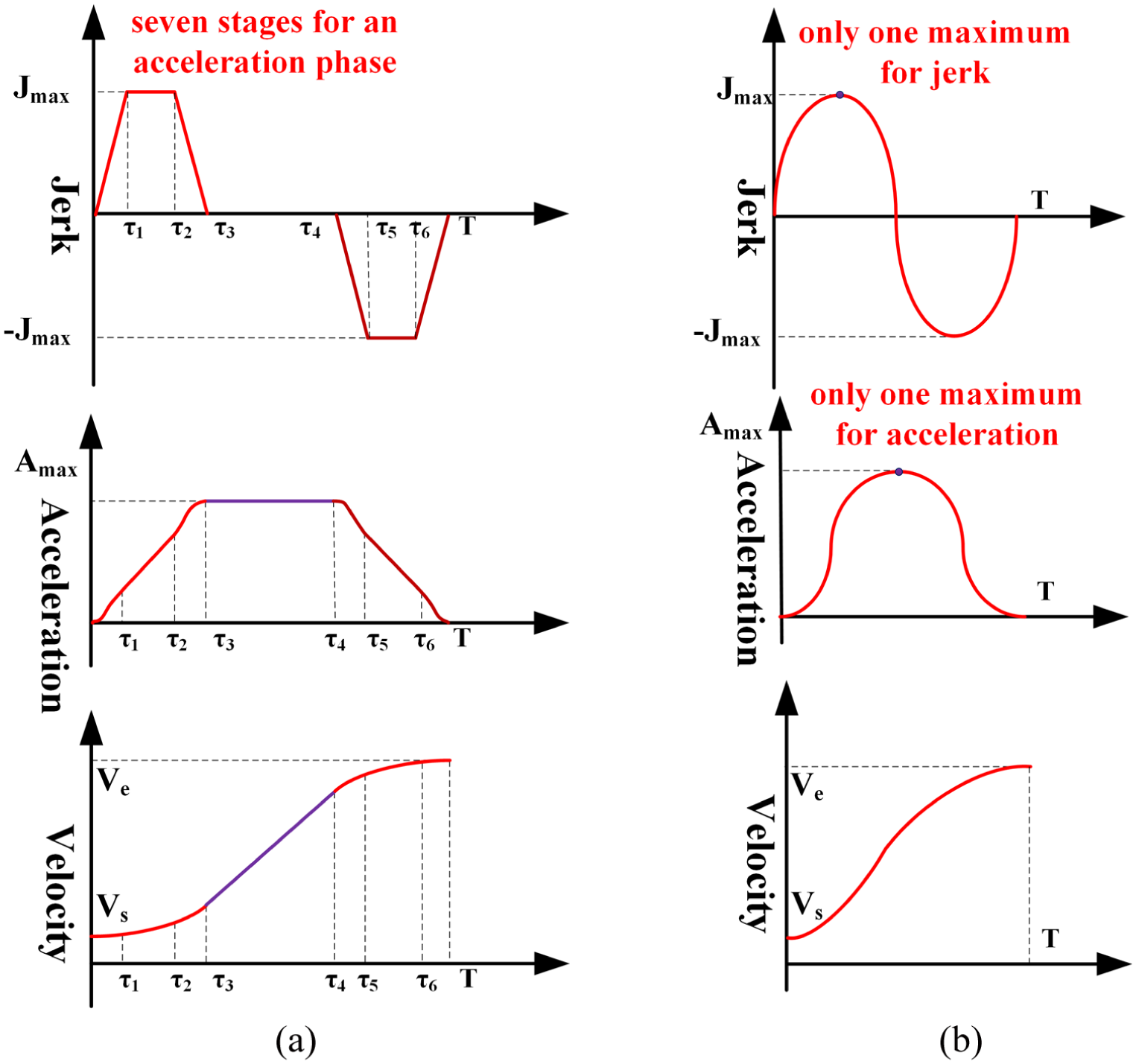
Two conventional AD feedrate profiles: (a) polynomial feedrate profile and (b) single sine feedrate profile.
In summary, the AD feedrate scheduling method is now most widely used in CNC systems due to its stability and low computational burden, 15 although there are some pitfalls, especially when the dynamic characteristics of each axis are dramatically unmatched.10,17 The study towards AD feedrate scheduling focuses on polynomial14,21,23 and trigonometric16,17,22 profiles, which usually concerns the constraints of tangential velocity, tangential/normal acceleration, tangential/normal jerk and chord error (only for parametric curves). Comparatively, the polynomial profile is more efficient than the trigonometric one because it can make full advantage of the axial capabilities, but the trigonometric representation is more succinct than the polynomial one and is more convenient to generate smoother profiles.
To obtain a jerk-continuous feedrate profile with both simplicity and efficiency, this article proposes an approach to represent the jerk profile using the sine series. By selecting the geometric sequence as the coefficients of the sine series, the closed-form expressions of the feedrate, acceleration and jerk profiles are obtained. By selecting the optimal geometric sequence, a short AD time duration is obtained. The remainder of this article is organized as follows. The feedrate profile based on the sine series representation of jerk profile is presented in section ‘Feedrate profile based on the sine series representation of jerk profile’. The procedure for AD feedrate scheduling using this kind of feedrate profile is detailed in section ‘AD feedrate scheduling for parametric curves’. Simulation and experimental results are given in section ‘Simulation and experimental results’, and conclusions are summarized in section ‘Conclusion’.
Feedrate profile based on the sine series representation of jerk profile
Principles of AD feedrate profile
An AD feedrate scheduling is to use a certain feedrate profile to connect the feedrate from one value to another one under given constraints. Following the idea of Luo et al.,
17
a profile with only an acceleration phase is adopted to illustrate the techniques of AD feedrate scheduling. Let the start velocity, the end velocity and the length of the path be
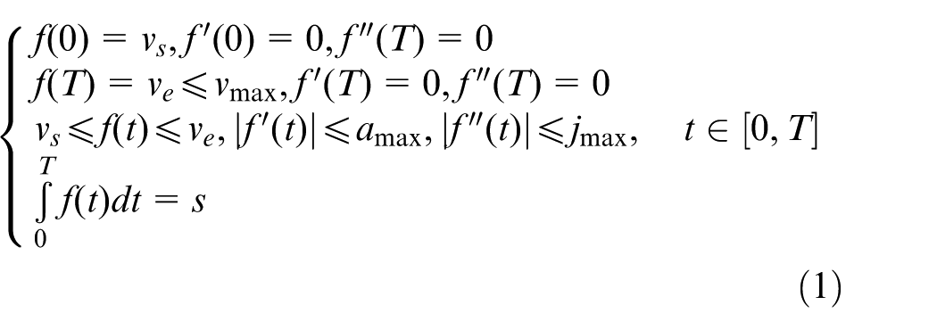
where t denotes the time; T is the time required to finish the path;
For a general AD feedrate profile, three principles are normally accepted to guarantee the machining efficiency according to some studies.21–24,26,27
Principle 1
There are three basic phases of an AD feedrate profile, that is, ACC (ACCeleration), CF (Constant Feed) and DEC (DECeleration), as illustrated in Figure 2. And there are seven practicable types of feedrate profiles, that is, ACC + CF + DEC, ACC + DEC, ACC + CF, CF + DEC, ACC, DEC and CF, as illustrated in Figure 3. If the symmetrical AD characteristics are applied, which is normally accepted17,21,22,26 and will be accepted in this article, it is adequate to only study the ACC phase to determine a proper feedrate profile.
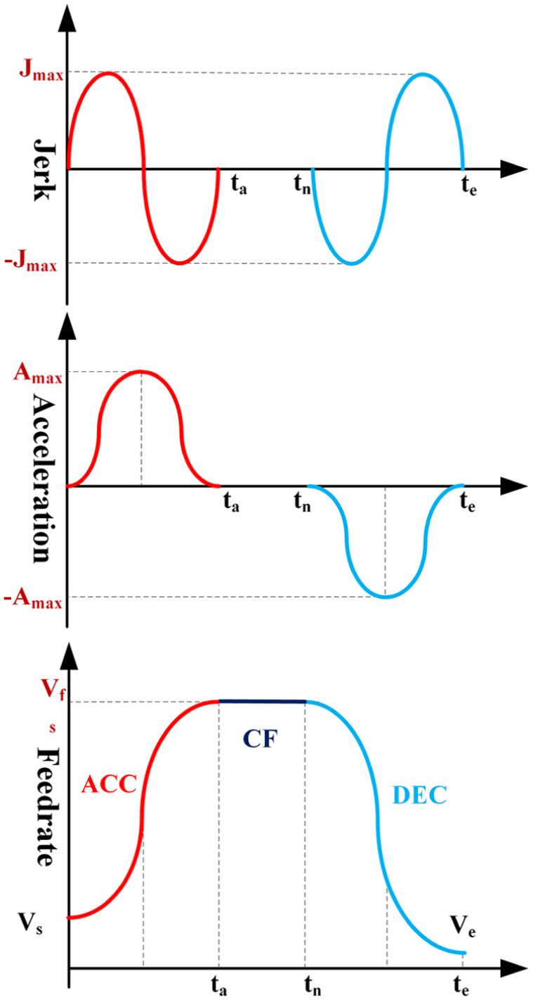
ACC + CF + DEC profile.
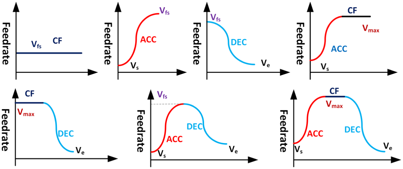
Seven practicable profiles of AD method.
Principle 2
The main aim of the feedrate scheduling is to make the feedrate as large as possible, rather than maximize the jerk or acceleration.
Principle 3
If the feedrate profile consists of more than a CF phase, for example, an ACC + CF profile, the velocity at the CF phase must be the maximum velocity according to Principle 2. Thus, the CF + DEC and ACC + CF profiles are rare in practice because the start or end velocity of the segment is usual not the maximum velocity.
Representation of AD feedrate profiles
Following the works of Luo et al. 17 and Lee et al., 22 the two conventional profiles, that is, the polynomial and the single sine feedrate profiles, are briefly revisited. Then, a novel feedrate profile derived from the sine series representation of jerk profile is presented with the aim of combining the advantages of the two conventional ones.
Polynomial feedrate profile
The simplest polynomial profile is the linear-velocity profile, of which the acceleration is confined. By selecting the order of the polynomial functions, one can get different feedrate profiles with desired order of continuity.12,19,23,26 A polynomial feedrate profile with a trapezoidal jerk and confined jounce is depicted in Figure 1(a). The ACC profile given in Figure 1(a) should be divided into 7 regions, and an ACC + CF + DEC profile should be divided into up to 15 regions. The expression of the limited-jounce feedrate profile and procedure of the scheduling are presented in Fan et al., 23 which are very cumbersome and will become more complicated as the profile gets smoother.
Single sine feedrate profile
Lee et al. 22 proposed a feedrate scheduling method with a velocity profile expressed as a single sine function and got the acceleration and jerk by the time derivatives of velocity. Unlike the piecewise function for a polynomial profile, the single sine feedrate for an ACC profile can be expressed with only one formula. The concision of expression, however, cannot cover its inefficiency. As shown in Figure 1(b), a single sine function results in only one point that can reach the maximum acceleration or jerk for the acceleration or jerk profile, respectively, which surely cannot make full advantage of the dynamic characteristics of the servo system.
Sine series feedrate profile
To combine the advantages of the polynomial and the single sine feedrate profile, a novel feedrate profile is derived here from the sine series representation of jerk profile. Contrary to Lee’s work, the jerk profile is determined first, and then the acceleration and velocity profiles are obtained by the time integrations, which results in a feedrate profile with a continuous jerk rather than a confined jerk.
Note that the jerk profile in an ACC phase usually has the shape of an odd function with translation along the x-axis as shown in Figure 1; thus, the jerk profile in an ACC phase can be expressed as a sine series according to the theory of Fourier series. The involved sine functions have the following forms
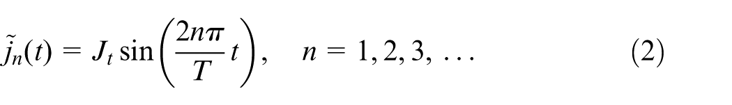
where
Considering the boundary condition
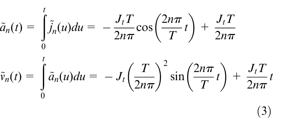
Normalizing the velocity yields
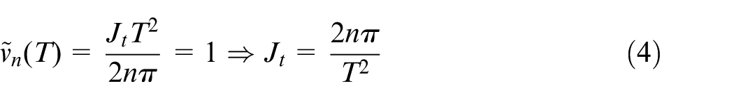
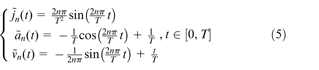
Substituting equation (4) into equation (3), we get the normalized jerk, acceleration and velocity as shown in equation (5)
In a general situation with start velocity
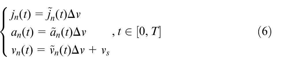
where
For the sine feedrate function with order n, we obtain the tracking length in the ACC phase by integrating the velocity w.r.t. time
It can be deduced from equation (7) that the tracking length is independent of the order of the sine function and determined only by the start velocity, the end velocity and the time duration.
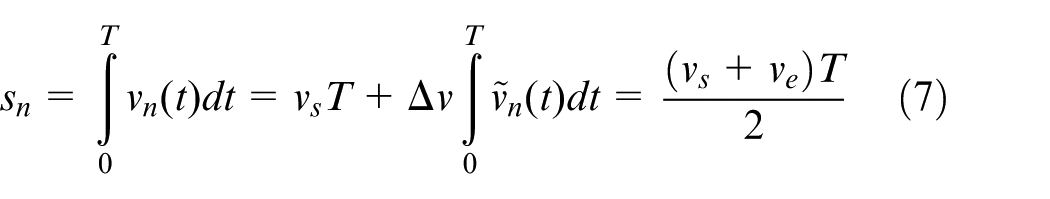
Therefore, we get the general feedrate profile as follows
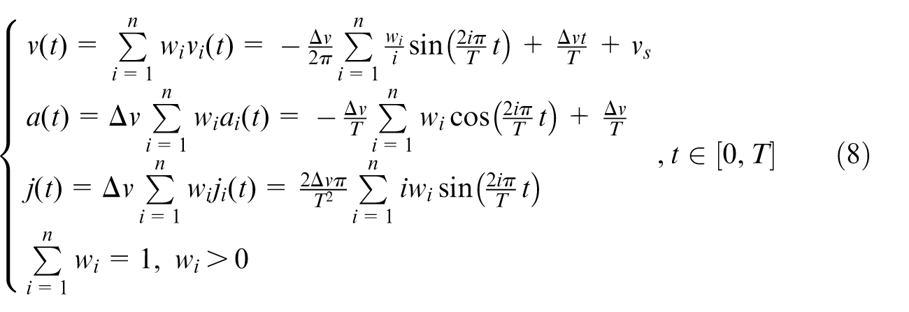
where
According to equation (5) and

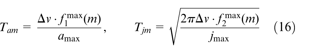
In order to reduce the total time for the contour tracking, the time for the acceleration phase should be minimized, that is, the time duration T for the ACC phase should be as small as possible. From equations (8) and (9), the time duration T can be determined by the following equation
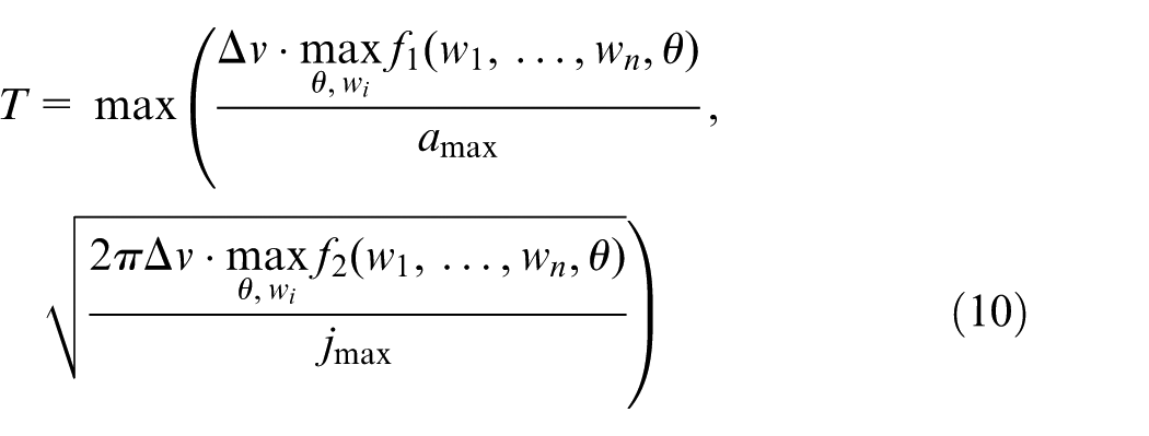
where
Coefficients of the sine series
To make sure that the series in equation (8) have closed-form expressions and the maximum acceleration and jerk can be efficiently determined, we use the geometric sequence as the coefficients of the sine series. Other coefficients are feasible, but the geometric sequence is one of the most intuitive and convenient choices.
Given the coefficients as geometric sequence defined in equation (11)
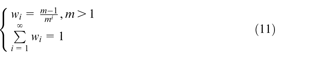
we obtain
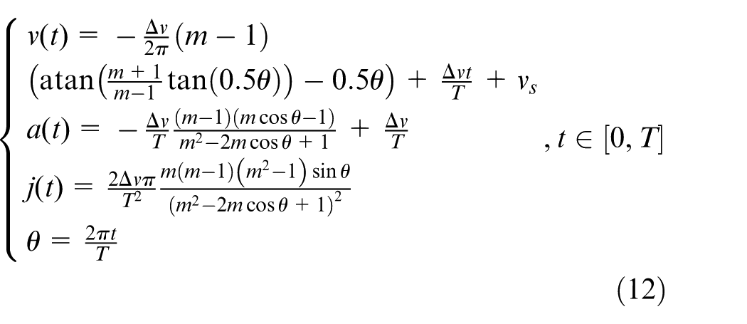
and
The derivations of equations (12) and (13) are given in Appendix 1.
Optimal coefficients of the sine series
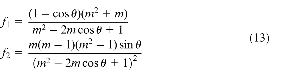
In order to obtain the optimal coefficients of the sine series which minimize T, we need to minimize the maximum value of the functions
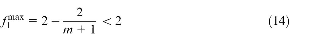
The maximum value of
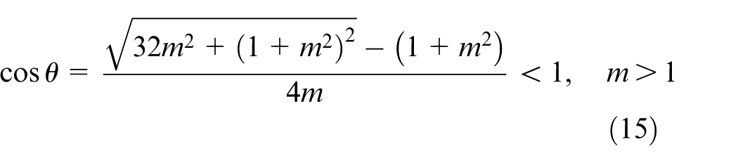
The detailed derivations of equations (14) and (15) are given in Appendix 2. The maximum values of
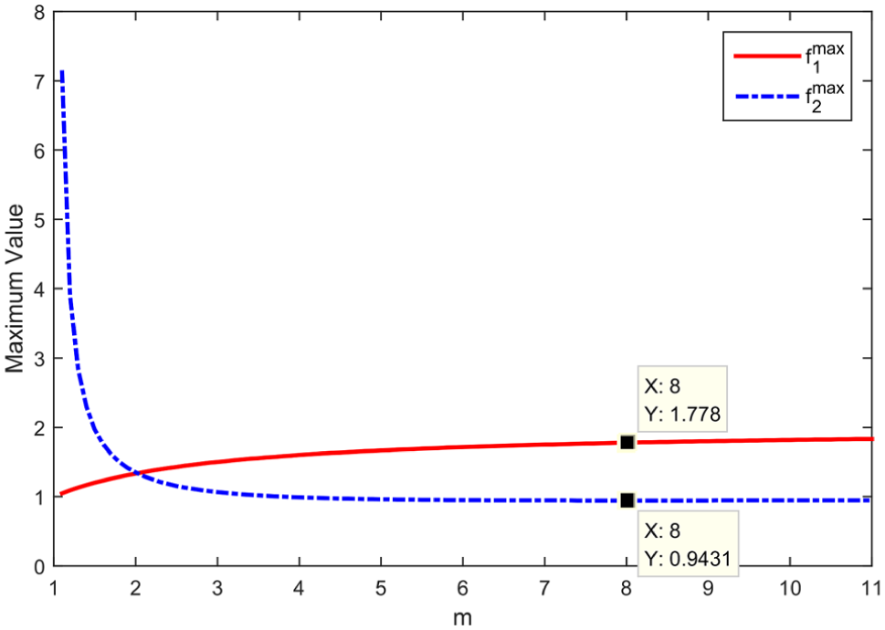
Maximum values of
For the conventional single sine function, we have
Let
Obviously,
As shown in Figure 4,
Let h be the search step, then a numerical search algorithm is proposed to determine the optimal m, which goes as follows:
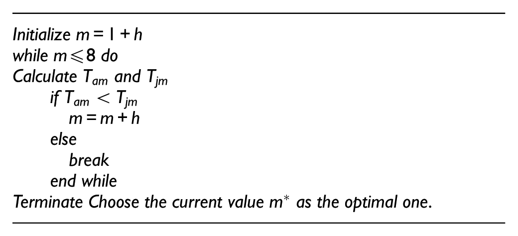
This search algorithm has three resulting cases as shown in Figure 5. In case I,
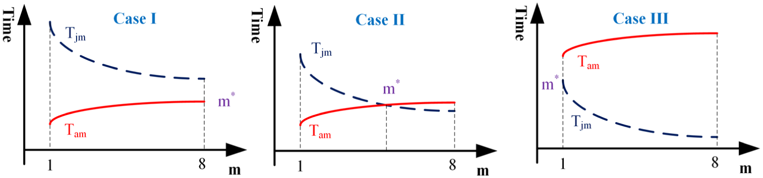
Three cases of the search algorithm.
AD feedrate scheduling for parametric curves
Procedure for AD feedrate scheduling
The AD feedrate scheduling method was first developed for linear tool paths, and then applied to parametric tool paths. For a linear tool path, the nominal velocity at each corner point can be determined by the angle between two adjacent lines.17,22 For a parametric tool path, the procedure for AD feedrate scheduling normally consists of the pre-processing, the feedrate profile generation and the interpolating stages. It has been well studied in Lin et al., 21 Lee et al. 22 and Fan et al. 23 Here, our work focuses on the feedrate profile generation stage.
In the stage of pre-processing, the critical points of the tool path, where the curvature reaches local maximum values and exceeds the threshold curvature
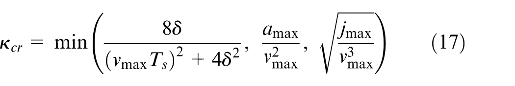
With these critical points, the whole tool path is splitted into several segments, of which the length can be calculated with adaptive Simpson quadrature formula. 28 After that the nominal velocity at each critical point is calculated by the following equation21,22
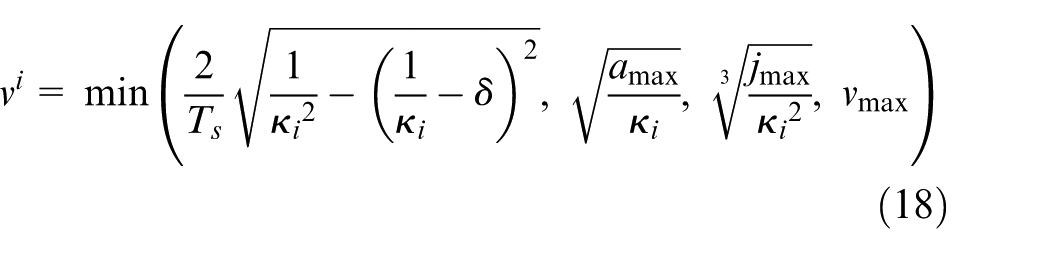
where
In the stage of feedrate profile generation, the proposed AD feedrate profile is applied to connect the nominal velocities at the critical points for each segment. The flowchart to determine the whole feedrate profile for the complete curved tool path is illustrated in Figure 6, which is similar to that in Lee et al. 22 The only difference between them is that in our method, the optimal m employed in the ACC and DEC phases should be determined using the method presented in section ‘Optimal coefficients of the sine series’. So, the efficiency of the conventional AD feedrate scheduling algorithms is completely preserved.
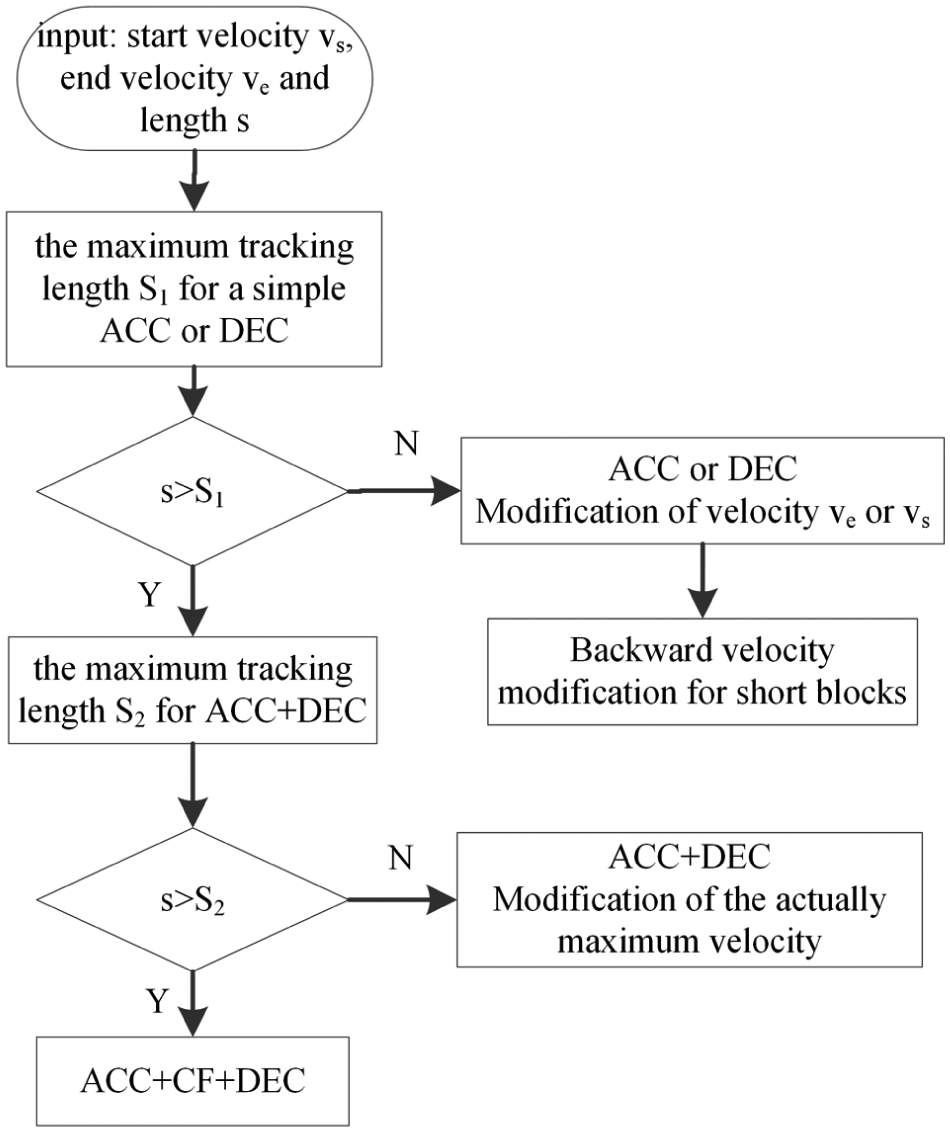
Flowchart of the proposed feedrate scheduling method.
The details to determine the complete feedrate profile for each segments with start velocity
Step I
In the first step, the maximum tracking length
Step II
In the second step, the maximum tracking length
Step III
In this step, an ACC + CF + DEC profile is assigned to the segment, which means that the velocity first accelerates from
In the stage of interpolating, the parametric interpolator based on the second-order Taylor expansion 29 is adopted to generate the reference position commands.
Dichotomy technique for velocity modification
As mentioned in section ‘Principles of AD feedrate profile’, there are seven practical types of an AD feedrate profile depending on the start velocity, the end velocity and the length of the segment. And in three cases, that is, ACC + DEC, ACC and DEC, a dichotomy technique is adopted to modify the actually maximum velocity, to ensure that the tracking length matches the segment length.
An ACC + DEC profile is taken as an example to illustrate the dichotomy technique. The tracking length of this profile is a monotonically increasing function of the actual maximum velocity

where
Backward velocity modification for short blocks
According to Figure 6, if
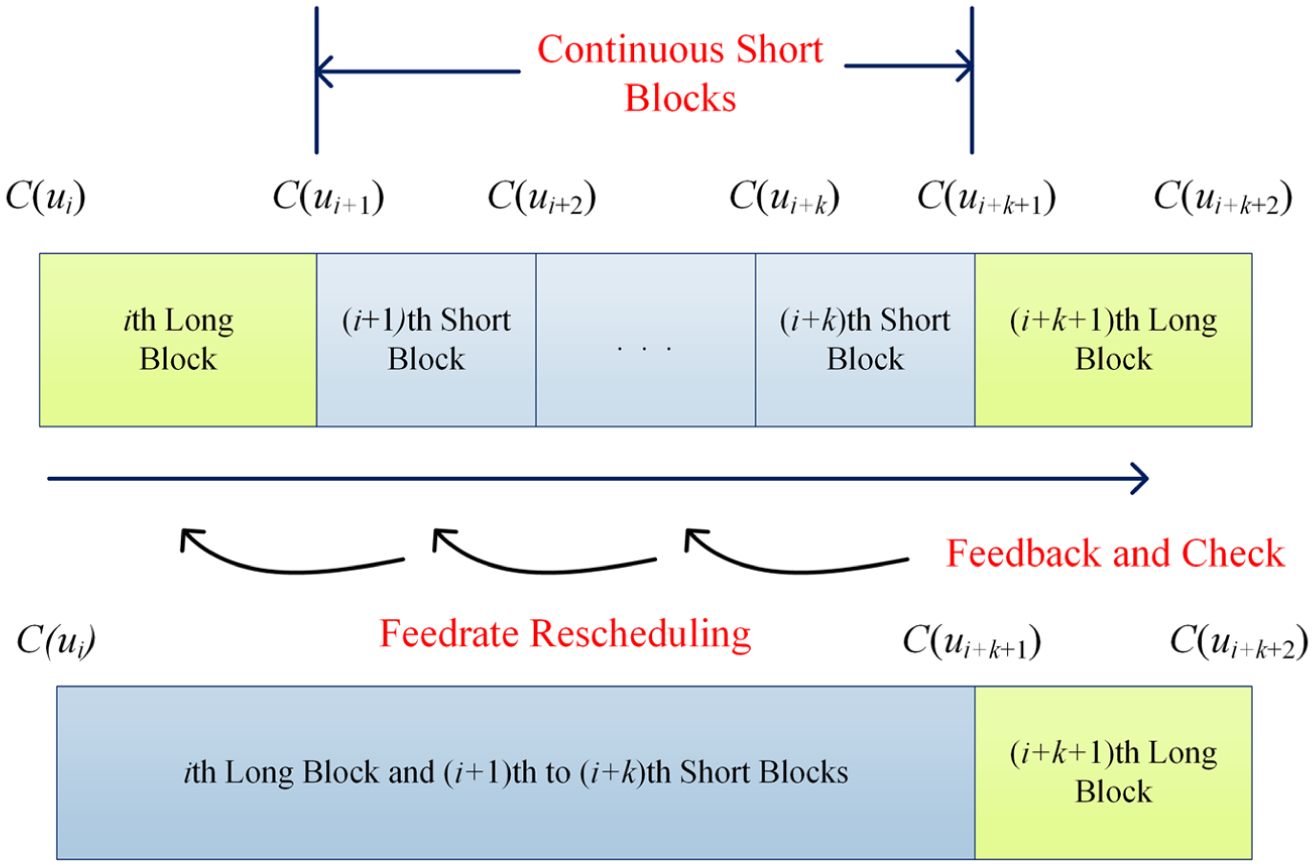
Procedure to handle short blocks.
Simulation and experimental results
Experimental setup
To illustrate the effectiveness of the proposed method, simulations and experiments of tracking complex contour expressed as non-uniform rational B-spline (NURBS) curve are conducted on a triaxial table driven by the YASKAWA SGDV series servo drivers and SGMJV motors, as shown in Figure 8. The lead of the ball screws used is 10 mm/rev, and the incremental encoder for each motor has a resolution of 10,000 pulses/rev. The off-line feedrate scheduling algorithm and the on-line control task are implemented on MATLAB environment and a dSPACE DS1103 system, respectively.
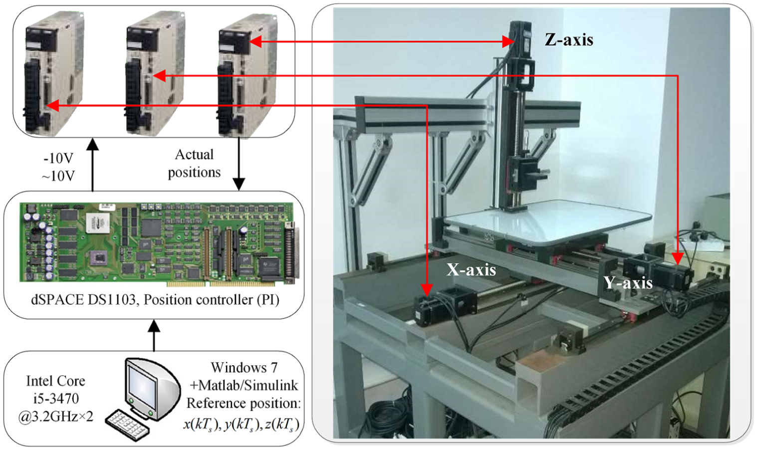
Layout of the triaxial experimental system.
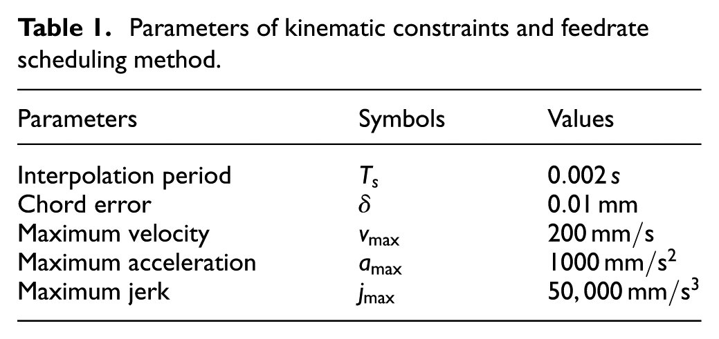
The parameters used in the feedrate scheduling and interpolation are listed in Table 1. The reference position commands generated by the interpolator are sent to the dSPACE system for motion control. The effectiveness of the sine series feedrate profile is demonstrated via the machining times in simulations and the contour errors in experiments.
Parameters of kinematic constraints and feedrate scheduling method.
Tracking of trident NURBS curve
The first NURBS curve is a trident curve shown in Figure 9(a), and the associated control points, weight vectors and knot vectors are listed in Table 2 of Appendix 3. The seven critical points determined by the given constraints are marked with star as shown in Figure 9, with which the curve is splitted into six segments. In Figure 9(a), the solid blue, the solid red and the dashed blue curves represent the shape, the control polygon and the lines connecting the critical points of the trident curve, respectively.
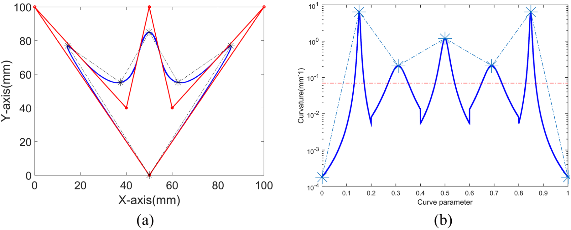
Trident curve and the selected critical points: (a) trident curve and (b) curvature of trident curve.
The simulation results shown in Figure 10 indicate that the machining time reduces from 3.126 s obtained with the single sine method to 2.577 s obtained with the sine series method, decreasing by 17.6%. The experimental results are given in Figure 11. The maximum and mean contouring errors resulting from the sine series method are 15.7 and 3.6 µm, respectively, while those resulting from the single sine method are 13.8 and 2.2 µm, respectively. The performances of the two methods in terms of accuracy are very similar.
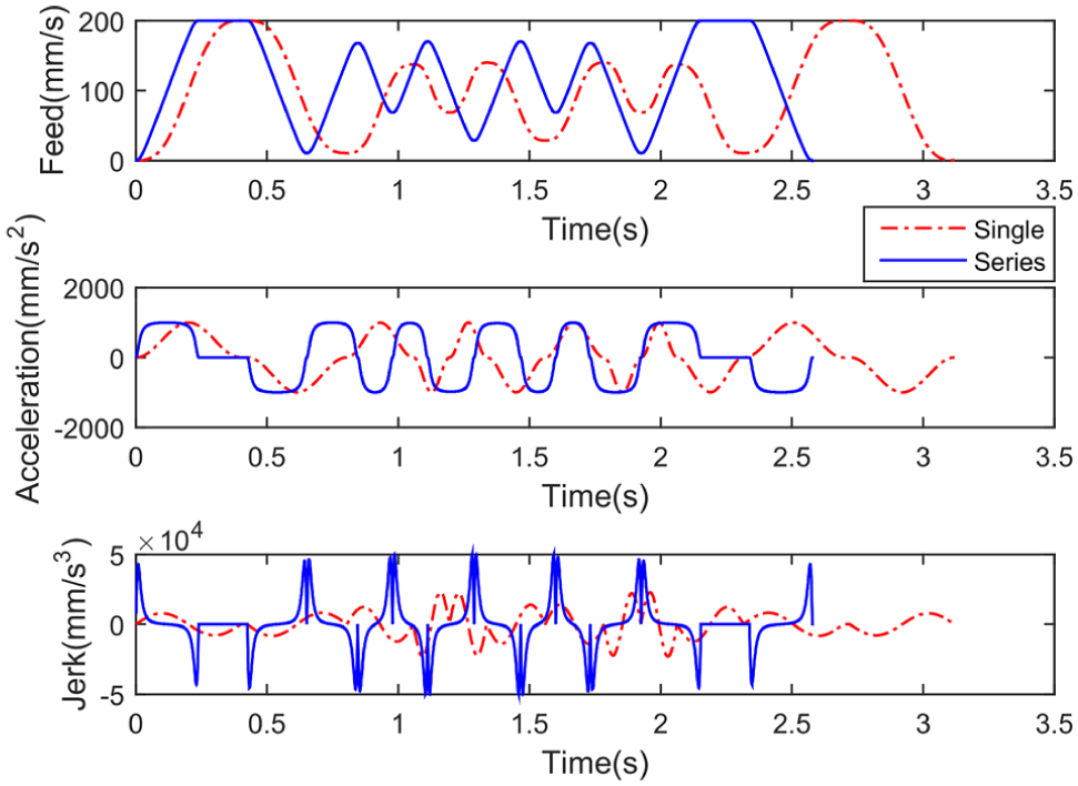
Simulation results of tracking trident curve.
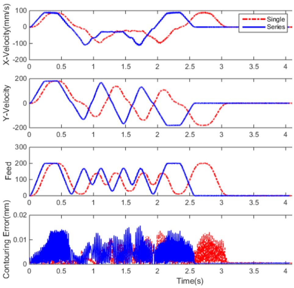
Experimental results of tracking trident curve.
Tracking of butterfly NURBS curve
The second NURBS curve is a butterfly curve shown in Figure 12(a), and the associated control points, weight vectors and knot vectors are listed in Table 3 of Appendix 3. A total of 37 critical points are determined and marked with star in Figure 12(a). As a result, the butterfly curve is splitted into 36 segments.
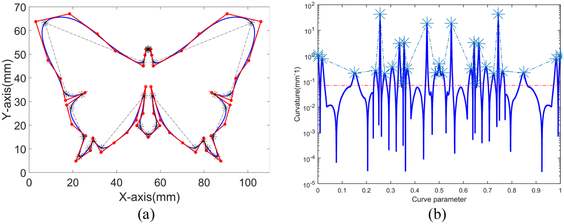
Butterfly curve and the selected critical points: (a) butterfly curve and (b) curvature of butterfly curve.
The simulation results shown in Figure 13 indicate that the machining time decreases from 5.427 s obtained with the single sine method to 4.802 s obtained with the sine series method, decreasing by 11.52%. The experimental results are illustrated in Figure 14. The maximum and mean contouring errors resulting from the sine series method are 20.9 and 3.9 µm, respectively, which are also very close to the results 19.9 and 3.6 µm obtained with the single sine method.
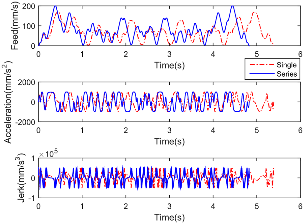
Simulation results of tracking butterfly curve.
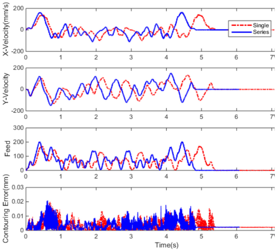
Experimental results of tracking butterfly curve.
As mentioned before, with the single sine method, only one point on the acceleration profile can reach the given maximum acceleration
Conclusion
This article presents the sine series representation of jerk profile for AD feedrate scheduling of parametric interpolator used in CNC machine tools. To the best knowledge of the authors, this work is the first attempt in introducing the sine series representation in AD feedrate scheduling under the velocity, acceleration, jerk and chord error constraints. The distinctive characteristics of the proposed method are summarized as follows:
It can generate a jerk-continuous feedrate profile and thus provide smooth feed motions for the machine tools, which benefits greatly to the contour following performance.
It is both efficient and concise. Using the sine series representation of jerk profile, various flexible and efficient jerk profiles can be obtained. By selecting the optimally geometric sequence as the coefficients of the sine series, the closed-form expressions of the feedrate profile that leads to a short AD time duration is obtained. The resulting feedrate scheduling method can generate a more efficient feedrate profile while keeping a similar maximum contouring error as compared with the conventional feedrate scheduling method that employs the trigonometric profile.
Footnotes
Appendix 1
Appendix 2
Appendix 3
Declaration of conflicting interests
The author(s) declared no potential conflicts of interest with respect to the research, authorship and/or publication of this article.
Funding
The author(s) disclosed receipt of the following financial support for the research, authorship, and/or publication of this article: This work was partially supported by the National Natural Science Foundation of China under grant no. 51325502 and the Science & Technology Commission of Shanghai Municipality under grant nos 13JC1408400 and 14111104801.