
Abstract
Instantaneous undeformed chip thickness is one of the key parameters in modeling of micro-milling process. Most of the existing instantaneous undeformed chip thickness models in meso-scale cutting process are based on the trochoidal trajectory of the cutting edge, which neglect the influences of cutter installation errors, cutter-holder manufacturing errors, radial runout of the spindle and so forth on the instantaneous undeformed chip thickness. This article investigates the tooth trajectory in micro-milling process. A prediction model of radial runout of cutting edge is built, with consideration of the effects of the extended length of micro-milling cutter and the spindle speed. Considering the effects of cutting-edge trochoidal trajectory, radial runout of cutting edge and the minimum cutting thickness, a novel instantaneous undeformed chip thickness model is proposed, and the phenomenon of single-tooth cutting in micro-milling process is analyzed. Comparisons of cutting forces under different chip thickness models and experimental data indicate that this new model can be used to predict cutting forces.
Introduction
The construction of instantaneous undeformed cutting thickness model is important to establish the cutting force model. The calculation accuracy of instantaneous undeformed chip thickness model influences the prediction accuracy of cutting forces directly. In the field of mechanical machining, meso-scale is between macro-scale and micro-scale, with the part size scope 0.1–10 mm and the geometric characteristic size scope 0.01–0.1 µm. 1 Under meso-scale cutting conditions, the scope of feed per tooth is 0.1–1 µm, the diameter of micro-milling cutter ranges from 0.1 to 1 mm2 and the stress variation on the tiny body of the micro tool is much higher than that on a conventional scale tool. 3 In order to guarantee sufficiently high cutting speed; high-speed spindle is usually used in meso-scale cutting, the rotate speed of which can be higher than 100,000 r/min, so the radial runout of cutting edge should not be neglected. The coupling effect of cutter installation errors, tool holder manufacturing errors, radial runout in rotational process of cutter and so forth will lead to the radial runout of the cutting edge with respect to the workpiece, 4 which greatly impacts micro-milling cutting-edge trajectories and then influences the calculation of cutting thickness. Additionally, Ramos et al. 5 and Malekian et al. 6 believed that influenced by the minimum cutting thickness in the meso-scale cutting process, chips will be produced discontinuously. Generally, the mechanical models for micro-milling were based on the conventional scale models, and some modifications were adopted to meso-scale milling.7–10
Now extensive studies on the instantaneous undeformed chip thickness model in meso-scale cutting process have been done by the scholars all around the world. Considering the influences of the trochoid movement track of the cutting edge and the spindle radial runout, Bao and Tansel11,12 developed the model of instantaneous undeformed chip thickness in micro-cutting process, based on which the prediction model of cutting force was established. Considering the movement track of cutting edge and the effect of spindle radial runout, Fu et al. 13 developed an instantaneous undeformed chip thickness model and analyzed the phenomenon of single-tooth and multi-teeth cutting in micro-cutting process. Based on the true cutting-edge trajectories of end-milling cutter, Yan et al. 14 solved the instantaneous undeformed chip thickness using the method of compensating approximate instantaneous undeformed chip thickness model, the computation procedure of which was easy. Wang et al. 15 proposed the prediction model of cutting-edge trajectories according to cutter rotation errors and rotor vibration effect, meanwhile, put forward a method of calculating cutting-edge rotation errors and the amount of unbalance when clamping cutter based on which instantaneous undeformed chip thickness in micro-cutting process was established. Considering the cutting-edge radius, material strengthening, varying sliding friction coefficients and runout together, Zhou et al. 16 presented a micro end-milling cutting forces prediction methodology. In order to obtain uncut chip thickness, a generalized algorithm considering runout was proposed. De Oliveira et al. 17 studied the size effect in micro-milling process, and the minimum uncut chip thickness was determined.
However, the models they developed neglected the influence of elastic recovery on micro-milling forces. Considering the impacts on instantaneous undeformed chip thickness made by the trochoid trajectories of cutting edge, elastic recovery of materials, minimum cutting thickness and cutter vibration, Jun et al. 18 built up a complicated calculation model of instantaneous undeformed chip thickness in micro-cutting process. Lu et al. 19 established a cutting force prediction model during micro-milling process, which considered runout of cutting edge, elastic recovery and size effect. Li et al. 20 solved the intersection coordinate of previous cutter tooth trajectory and connected the line between cutting edge and cutter central line to set up instantaneous undeformed chip thickness model and then approximately solved it by using Taylor series expansion method. Kang and Zheng 21 established a cutting thickness model which was expressed by Fourier series, and the Fourier coefficients were expressed in terms of the ratio of feed per tooth to cutting-edge radius for different numbers of cutter teeth. The Newton–Raphson method was used to find the numerical solution for true chip thickness, and the results were more accurate than the model presented by Li et al. 20 Experimental coefficients are all-time difficult to determine by experiments, and some researchers are trying to obtain them by predicting specific force coefficients from a finite element method (FEM) cutting model. Based on the trochoid movement track of the cutting edge and the effect of spindle radial runout, Afazov et al. 22 developed an instantaneous undeformed chip thickness prediction model based on the FEM. Using cutting force coefficients obtained from finite element (FE) simulations, Jin and Altintas 23 presented a method to predict micro-milling forces.
As mentioned above, most of the existing instantaneous undeformed chip thickness models in micro-cutting process are based on the trochoid trajectories of cutting edge, which take spindle runout and elastic recovery of workpiece into account but neglect the influences of cutter installation errors, cutter-holder manufacturing errors, system rigidity and so forth on the instantaneous undeformed chip thickness. However, these factors are crucial; for instance, the tool setting which affects cutter installation error must be precise enough to ensure manufacturing accuracy; 24 and machine stiffness and machine act in a unique way in micro scale.25,26 The effects of cutter installation errors, cutter-holder manufacturing errors, spindle runout, system rigidity and so forth on the instantaneous undeformed chip thickness ultimately come down to the impact on instantaneous undeformed chip thickness made by the radial runout of cutting edge with respect to the workpiece. Now, Malekian et al., 27 Ahmadian and Nourmohammadi 28 and Zhang et al. 29 used receptance coupling method to obtain the dynamic response functions of cutting edge in micro-cutting process, but this method is very complicated and is heavy on computations.
A new method of measuring radial runout of cutting edge is proposed in this article. First, the radial runout of cutting edge is obtained based on the experiment and the prediction model of the radial runout of cutting edge is established based on the experimental data. Then considering the effects of trochoid trajectories of cutting edge, radial runout of cutting edge and minimum cutting thickness, the calculation models of the nominal instantaneous undeformed chip thickness and cumulative instantaneous undeformed chip thickness during the actual cutting process are established, simultaneously the single-tooth cutting phenomenon in micro-cutting process is analyzed. The research can make theoretical preparation for further study on micro-milling force model.
Research on cutting-edge radial runout in micro-milling process
The tool holder manufacturing error, cutter mounting error and radial runout of the spindle will cause radial position deviations of the tool relative to the axis of the spindle during the rotation of the cutter, namely, radial runout of cutting edge. The definition is derived from Anon. 4 The radial runout of the cutter will cause machining dimension variation during micro-milling process, which will reduce the machining accuracy. During micro-milling process, the cutting thickness is in sub millimeter range and even micrometer range, and the radial runout of the tooth will directly influence the trajectory of the cutting edge, causing variation in the instantaneous undeformed chip thickness. The prediction of the cutting force is based on the instantaneous undeformed chip thickness. Therefore, the influence of radial runout of cutting edge on cutting force cannot be neglected.
Experimental design
On the self-developed micro computer numerical control (CNC) milling machine, as shown in Figure 1, how spindle rotate speed and extended length of cutter influence the cutting-edge radial runout was studied by the experiments of milling micro-holes.
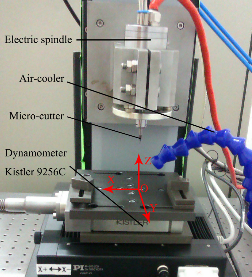
Developed micro CNC milling machine.
High-speed and high-precision electric spindle is used in the developed micro-milling machine, the maximum rotational speed of the electric spindle can be up to 140,000 r/min and the radial runout of the spindle is less than 2 µm. Ultrafine particle–coated cemented carbide end-milling tool with two flutes is used to mill micro-holes; the theoretical diameter of the milling tool is 0.6 mm, the length of edge is about 0.5 mm, the tool nose radius is about 2.02 µm and the helix angle is about
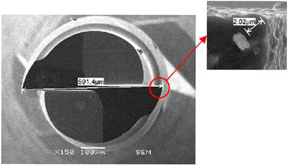
SEM photo of micro-milling cutter.
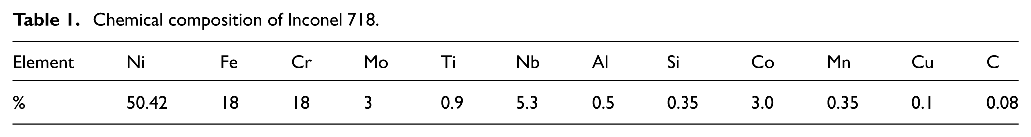
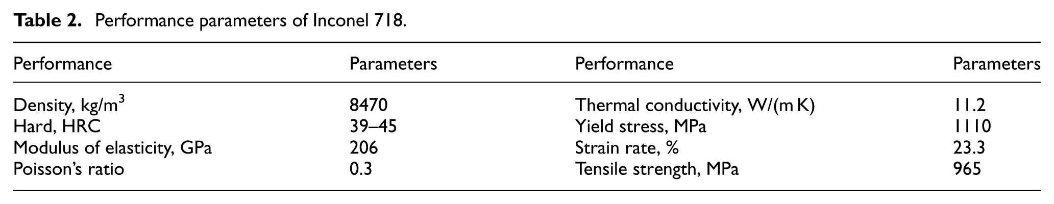
The workpiece, Inconel718, is a typical difficult-to-machine material. With the development of science and technology, the demand of micro parts and components for the fields of aerospace, biomedical, energy and power with high strength and corrosion resistance under high temperature circumstance is continuously increasing. With excellent high temperature strength, good thermal stability and thermal fatigue resistance, the nickel-based superalloy can well satisfy the material requirements of micro parts and components with high strength and corrosion resistance under high-temperature environment. Ucun et al. 30 researched the effect of tool coating materials on surface roughness in micromachining of Inconel 718 superalloy. There are no investigations about material removal mechanism in micro-milling of Inconel 718; therefore, the research on micro-milling mechanism and processing technology of nickel-based superalloy has important practical value. The chemical compositions of the workpiece are measured by energy spectrum analysis accessories produced by Oxford Instruments, which are shown in Table 1. The performance parameters of Inconel 718 are shown in Table 2. 31
Chemical composition of Inconel 718.
Performance parameters of Inconel 718.
The axial depth of micro-hole is 100 µm, and axial feed rate is 0.01 mm/s. The cutter will keep rotating in the micro-milling hole for 30 s, when the cutter feeds into the bottom of the hole during the micro-milling process. It is assumed that the spring back effect of material can be removed when the cutter keeps rotating in the hole for 30 s. At this condition, the cutting process can be regarded as micro drilling and the remaining material derived from spring back effect can be removed after cutting for 30 s. So the spring back effect can be neglected in the micro-milling experiments when modeling the magnitude of the total radial runout. In order to suppress interference, the depth of cut, radial depth of cut, feed rate and so forth were set to a constant value. Therefore, the effect of these factors can be neglected under the same cutting conditions, cutting tool and machine tool.
The actual diameter of micro-milling cutter is D; the measured diameter of micro-hole is
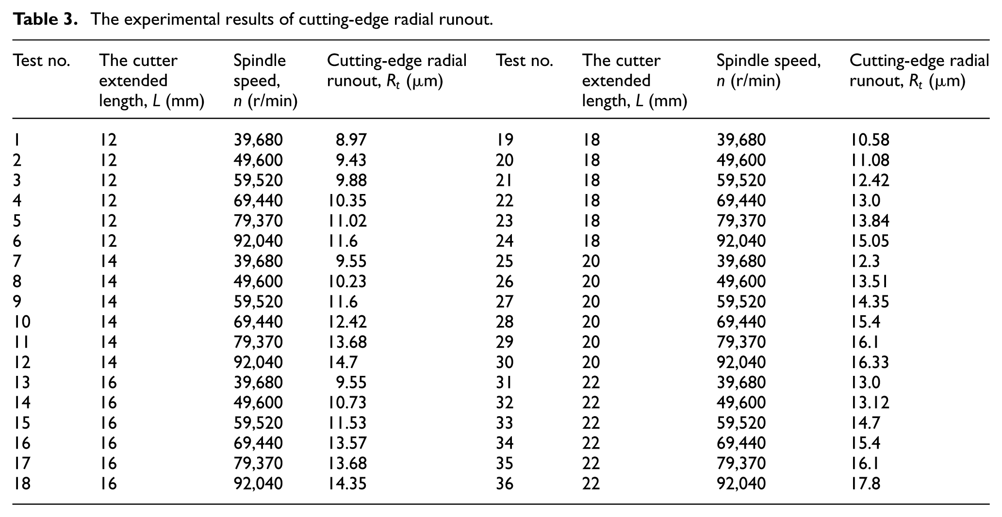
Taking cutter extended length and spindle speed as experimental parameters, respectively, as shown in Table 3, the influence law of cutting-edge radial runout was analyzed by applying the various factors. A total of 36 groups of experiments had been done, and in each group, five micro-holes were milled. The mean value of experiment results was chosen as the cutting-edge radial runout under this rotational speed condition.
The experimental results of cutting-edge radial runout.
The significance test is conducted by evaluating the parameter F with equation (1)
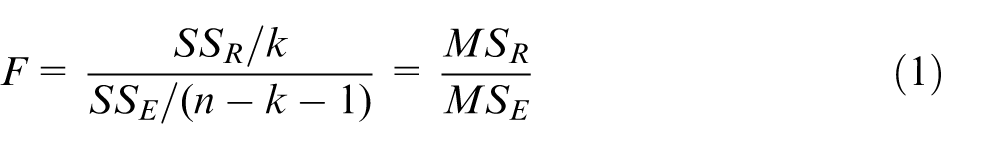
where n is test number and k is the number of variables. It is possible to evaluate the sum of squares due to the regression model
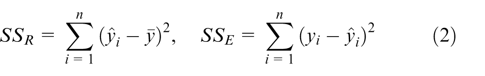
It can be regarded as significant with a confidence level
The sum of squares due to error
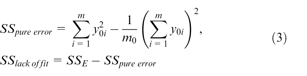
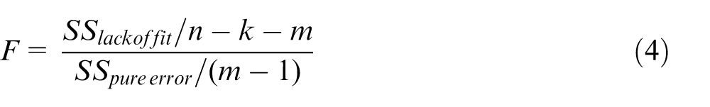
where m is the number of verification test. The lack of fit test is conducted by evaluating the parameter F with equation (4)
If
Experimental results and analysis
The experiment results of cutting-edge radial runout under conditions of different experimental parameters are shown in Table 3.
Based on the experimental data in Table 3, three-dimensional drawing plotted by MATLAB software is set forth, as shown in Figure 3, which shows the influence rule of cutter extended length and spindle speed on the cutting-edge radial runout.
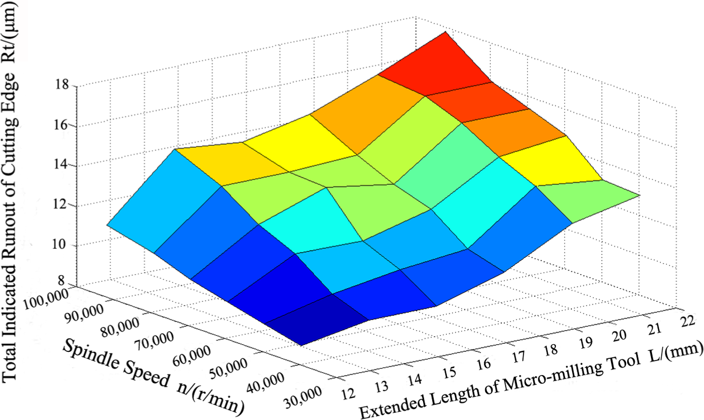
The influence rule of cutter extended length and spindle speed on the cutting-edge radial runout.
Prediction model of cutting-edge radial runout
The prediction model of cutting-edge radial runout can calculate arbitrary cutter extended length and spindle speed within the range of the experimental parameters. Using exponential formula equation (5) to fit experiment data, this study establishes the prediction model of cutting-edge radial runout. In order to unify units, cutting-edge radial runout with unit millimeter is used to carry on the data fitting

where
Equation (5) is a nonlinear equation. To determine the coefficients, logarithmic transformation is used to turn it into linear equation, as shown in equation (6). Based on the experimental data in Table 3, linear regress least square method is used to determine the coefficients of equation (6). The final solved prediction model is shown in equation (7)


The F inspection is used to do significance test on regression equation, and the variance analysis results are listed in Table 4.
The regression variance analysis table of radial runout of cutting edge.
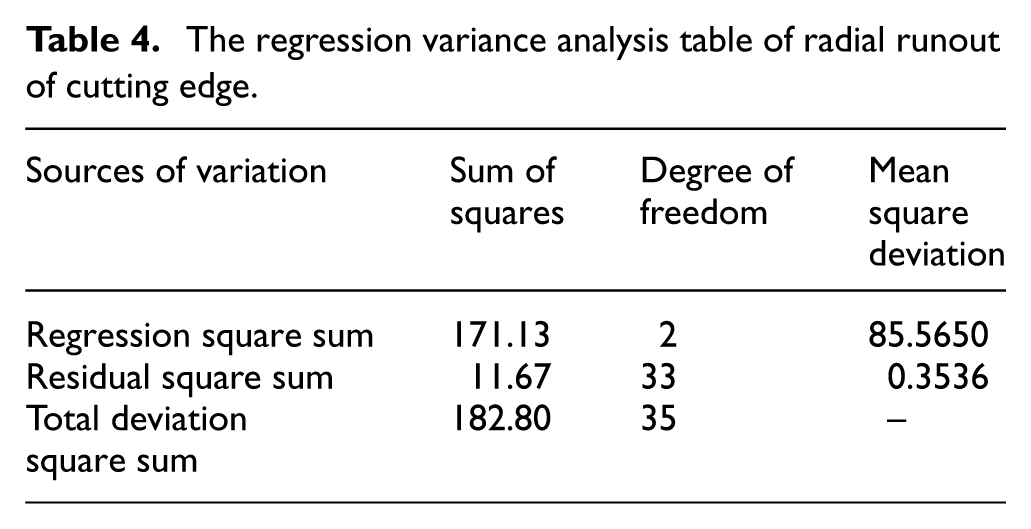
The test statistic F is 241.98, which was formed by the ratio of regression mean square deviation to residual mean square deviation. The critical value
The results of significant F inspection proved that the built prediction model of cutting-edge radial runout is highly significant. Relative fitting error of the regression equation is less than 0.0926, so the built prediction model fits the experimental results well at the testing points, however, which cannot confirm that the calculated value fitting the measured value well within the whole range of the parameters.
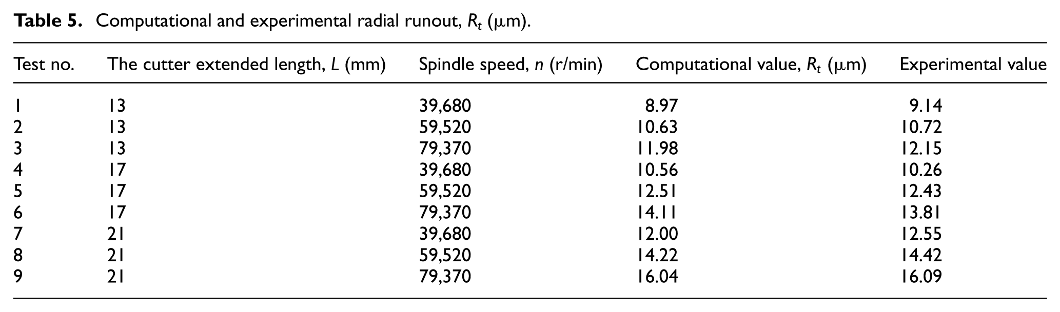
To confirm the effectiveness and accuracy of the established prediction model of cutting-edge radial runout, nine groups of experiments are done to test the fitting degree of regression equation at selected testing points within the range of parameters randomly. The comparison results between computational and experimental values are listed in Table 5. The F inspection is used to do fitting level test on regression equation, and the results are shown in Table 6.
Computational and experimental radial runout, Rt (µm).
The fitting degree test table.
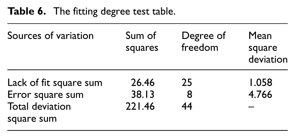
The test statistic F is 0.222, which was formed by the lack of fit mean square deviation and error mean square deviation. The critical value
So the established prediction model of cutting-edge radial runout applies to the prediction of cutting-edge radial runout.
Research on the cutting thickness model based on the radial runout of cutting edge
The cutting trajectories based on the radial runout of cutting edge
The cutting trajectory is related to the cutting-edge radius, angular velocity of the spindle, radial runout of cutting edge and the feed rate. Figure 4 is the diagrammatic sketch of trochoid trajectory of the cutting edge of the micro-milling cutter, in which x is the feed direction and y is perpendicular to the feed direction.
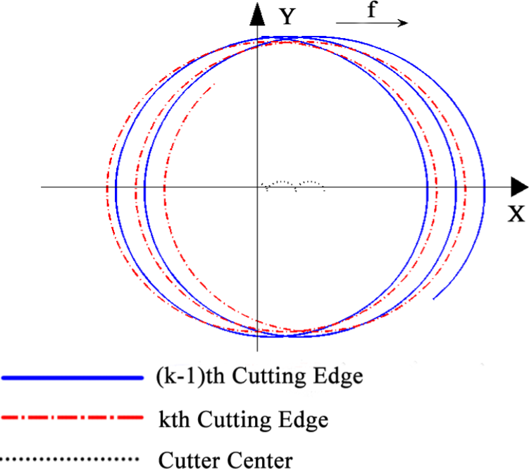
The trochoid trajectory of the cutting edge of the micro-milling cutter.
The position angle of the milling cutter tooth is defined as the angle between the positive direction of y axial and the line connecting the tooth point and the center line of the milling cutter. Clockwise direction is the positive direction and counterclockwise direction is the negative direction. Solid line means the tooth tip cutting track of the (k − 1)th tooth, dashed line means the tooth tip cutting track of the kth tooth and dash-dotted line means the center-line track of end face of the milling cutter. Therefore, equation (8) is used to express the trajectory of the kth tooth tip changing with time t
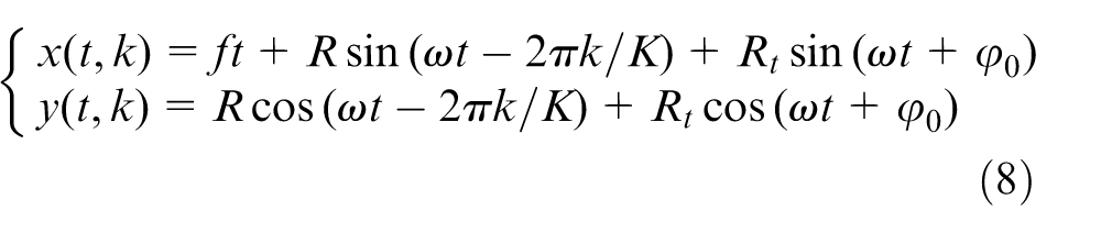
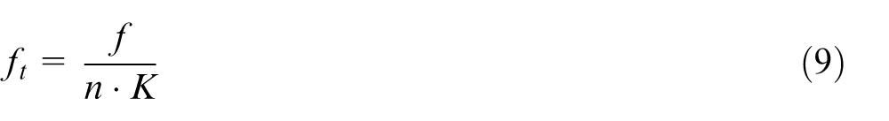
where f is the feed rate
Phenomenon of single-tooth cutting in the micro-cutting process
According to the traditional cutting theory, for the milling cutter with two flutes, the flute cut the workpiece by turns along the feed direction. Then the crescent shape of envelope between the two cutting-edge tracks represents the cutting thickness at each moment during the feed. As is shown in Figure 5, the instantaneous undeformed chip thickness indicates the instantaneous undeformed chip thickness when the tooth position angle is
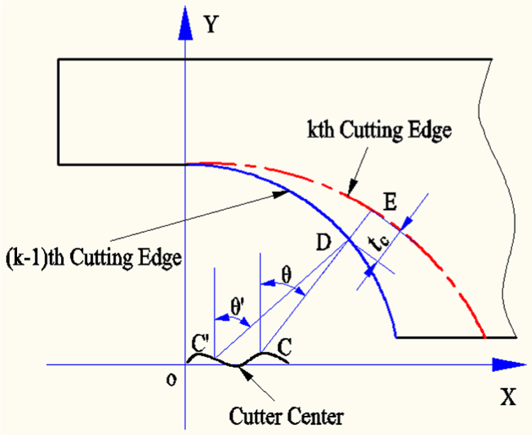
Diagrammatic sketch of instantaneous undeformed chip.
The schematic diagram of single-tooth cutting trajectory is shown in Figure 6. The cutting conditions are as follows: spindle speed is 39,680 r/min, feed rate is 1.2 mm/s, the diameter of two-edged milling cutter is 591.4 µm, radial runout of cutting edge is 11 µm and the initial angle of radial runout of cutting edge is 60°. The solid lines indicate the first tool path and the dash-dotted lines indicate second.
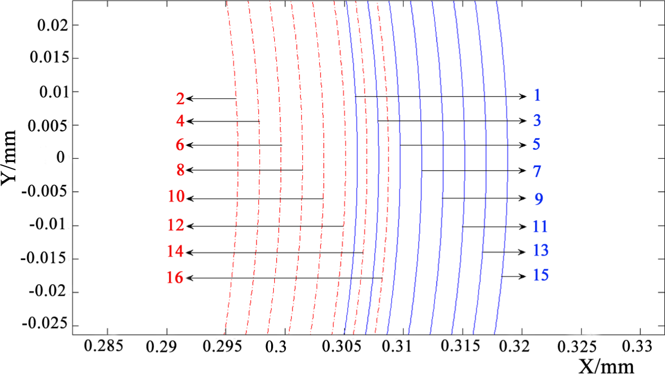
Schematic diagram of single-tooth cutting trajectory.
The numbers in Figure 6 show the order of cutting workpiece in chronological order. In this circumstance, it is quite obvious that the cutting tracks of both cutting edges cannot occur alternately. In each cutting period, the second cutting tracks always fall behind the first ones, that is, the single-tooth cutting phenomenon.
As can be seen from Figure 6, the numerical value of the instantaneous undeformed chip thickness differs from the conventional-scale cutting theory when the tooth position angle is
where
When the single-tooth cutting phenomenon occurs during the meso-scale milling and the tooth position angle is
For the milling process of k-tooth milling cutter, the discriminant to distinguish whether or not there is the single-tooth cutting phenomenon can be derived by geometric relationship, and it is given by
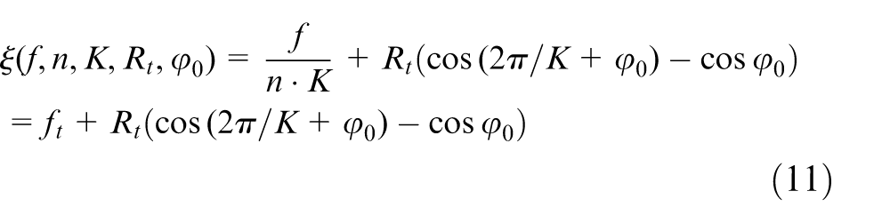
When
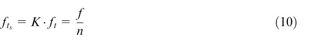
For macro-scale milling process, the feed per tooth is far more than radial runout of cutting edge, therefore
Micro-milling cutter with two flutes is often used. So equation (11) can be written as

When
Nominal instantaneous undeformed chip thickness model considering radial runout of cutting edge
As is shown in Figure 5, the nominal instantaneous undeformed chip thickness
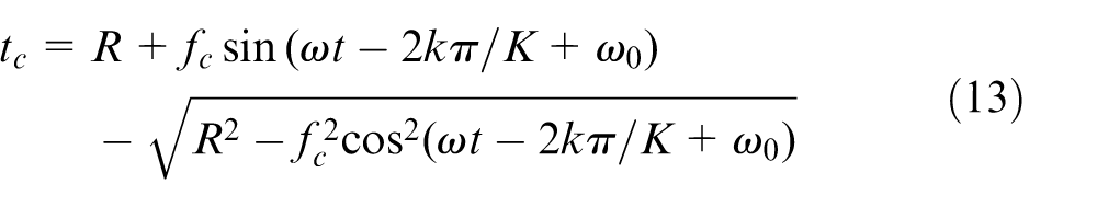
where the distance
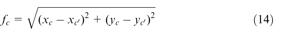

The coordinates of nodes C and
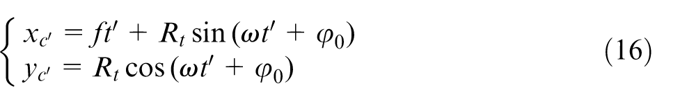
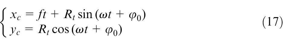
From Figure 5, we can see that the key to calculate the instantaneous undeformed chip thickness is to make sure that point C, D and E are on a straight line as well as derive the moment
When
When
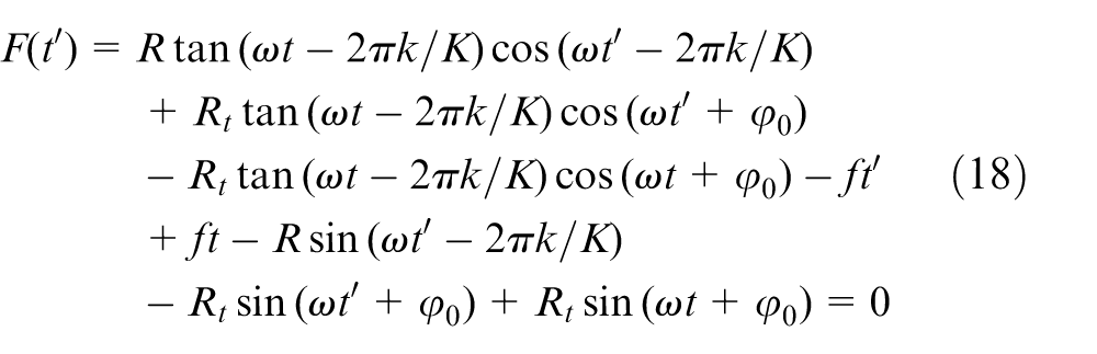
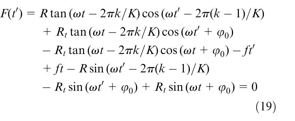
The Newton–Raphson method is used to solve the nonlinear equations (18) and (19). An initial value is given as
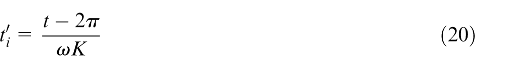
According to the iterative Newton–Raphson method, the time
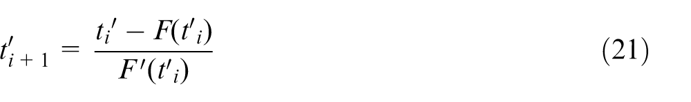
where
Instantaneous accumulation cutting thickness model in the actual cutting process
During the meso-scale cutting process, chips are formed discontinuously because of the minimum cutting thickness. When the instantaneous undeformed chip thickness is less than the minimum cutting thickness, the elastic-plastic extrusion and deformation occur mainly between the current cutting tooth and the workpiece, which interact each other with friction and plowing force, so no chips are formed. When the instantaneous undeformed chip thickness is close to the minimum cutting thickness, the phenomenon of the instantaneous accumulation cutting thickness appears along with plowing effect and shear effect, and no chips are formed. When the accumulated instantaneous undeformed chip thickness is more than the minimum cutting thickness, shear force will be the main interactive force between the cutting tooth and the workpiece, which indicates the formation of chips round by round. Therefore, the instantaneous accumulation cutting thickness of the kth tooth at t moment would be given by equations (22) and (23)
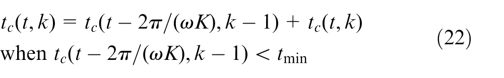
where
Considering the effect of the minimum cutting thickness, simulations of instantaneous accumulation cutting thickness are shown in Figures 8 and 9.
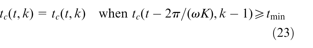
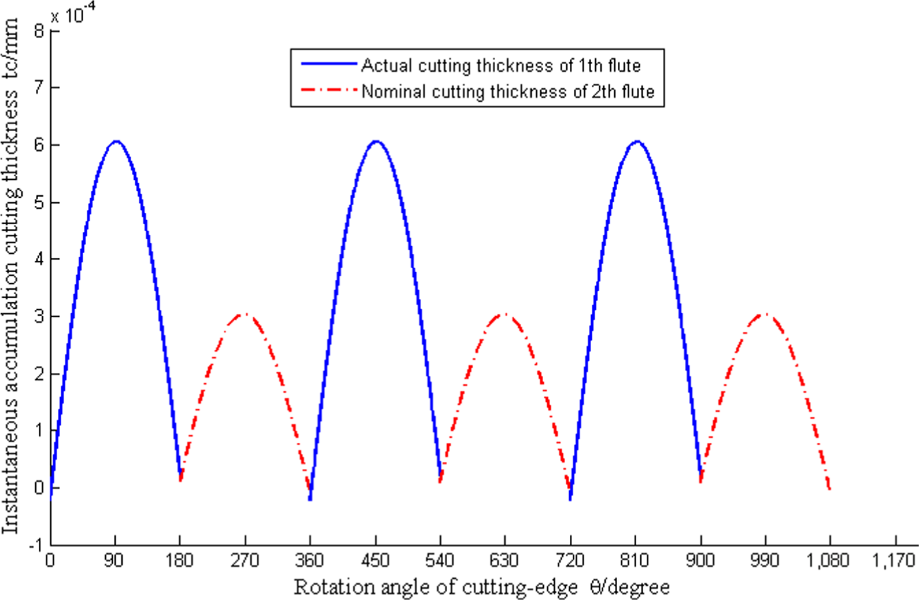
Figure 8 is the simulation of instantaneous undeformed chip thickness when feed per tooth is less than the minimum thickness. The simulation cutting conditions are as follows: a two-flute milling cutter is used with the milling cutter diameter 591.4 µm, the spindle speed is 39,680 r/min, the predicted radial runout of cutting edge is 11.7 µm, it is assumed that the initial runout angle is
The influence principle of feed per tooth on cutting forces.
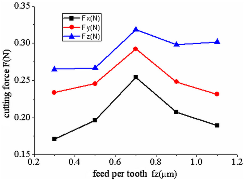
Figure 8 shows that, in the first cutting cycle, the first tooth only added up the cutting depth but did not produce the chips; the second tooth was affected by the tooth runout, just slipped away from the workpiece surface and did not cut it; in the second cutting cycle, the accumulated instantaneous cutting depth of the first tooth was higher than the minimum cutting thickness 0.7 µm and the chips produced, but the second tooth was remain uncut, which means the two cutting cycles only formed chip once at the first tooth, the second tooth did not cut in this cutting condition.
Instantaneous undeformed chip thickness when feed per tooth is less than the minimum thickness.
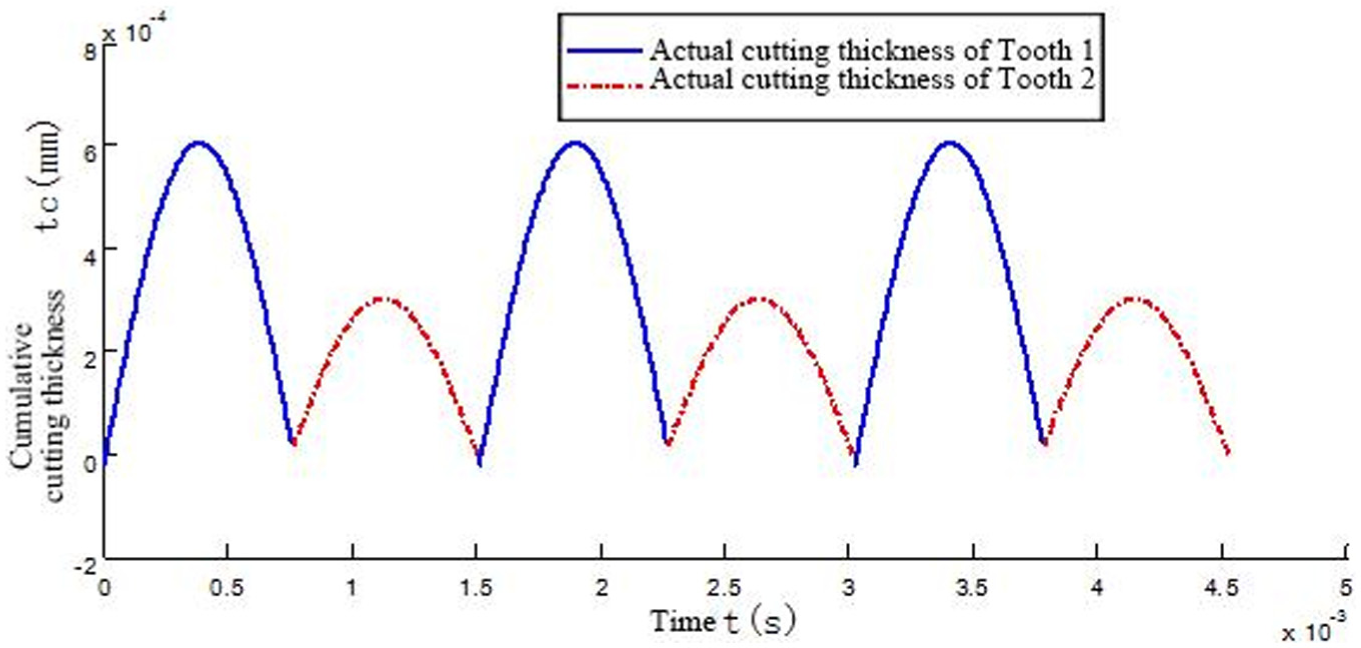
Figure 9 is the simulation of instantaneous undeformed chip thickness when feed per tooth is more than the minimum cutting thickness. The cutting conditions are as follows: the feed per tooth is 0.4 µm, and the other conditions are similar with those in Figure 8.
Instantaneous undeformed chip thickness when feed per tooth is more than the minimum thickness.
Figure 9 shows that the process is under the single-tooth cutting in this cutting condition. In the first cutting cycle, the first tooth cut the workpiece; the second tooth was affected by the tooth runout, just slipped away from the workpiece surface and did not cut it. So in one cutting cycle, the first tooth cut the workpiece, the cutting depth is higher than the minimum cutting thickness which produced the chip; the second tooth did not cut.
During the micro-milling process, the simulation of instantaneous undeformed chip thickness is shown in Figure 10 when single-tooth cutting phenomenon occurs.
Simulation of single-tooth cutting phenomenon.
The simulation cutting conditions of Figure 10: a flat end milling cutter with two flutes is used with the milling cutter diameter 591.4 µm, the spindle speed is 39,680 r/min, the predicted radial runout of cutting edge is 11.7 µm, it is assumed that the initial runout angle is
Experimental verification and analyses of the cutting forces’ prediction model
Cutting force in micro-milling process could serve as the validation of the proposed to reflect the proposed chip thickness model.
The minimum cutting thickness is used as demarcation point during micro-end milling process in this article. Cutting forces’ prediction model during shear-dominant cutting process and cutting forces’ prediction model during plowing-dominant cutting process are built respectively.
Axially discrete infinitesimal cutting forces’ prediction model of shear-dominant regime cutting process is built as following
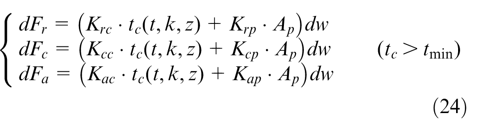
Since radial, tangential and axial forces of tool during micro-end milling cannot be measured directly, forces measured by dynamometer are forces of milling cutter on x, y and z axes. So cutting forces of infinitesimal,
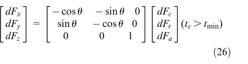
where
Three-dimensional cutting forces of infinitesimal can be gotten by putting equation (24) into equation (26)
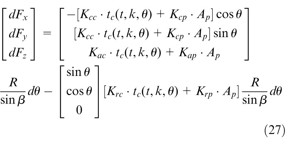
where,
Cutting forces of a single milling cutter cutting edge can be obtained by integrating infinitesimal cutting forces along cutting edge. Cutting forces of milling cutter during shear-dominant regime micro-end milling process can be gained by accumulating cutting forces of K cutting edges. The equation can be shown as follows
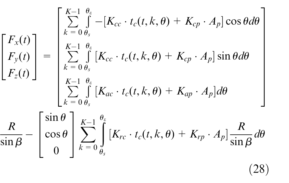
where
Equation (28) is three-dimensional dynamic model of cutting forces when actual cutting thickness is larger than the minimum cutting thickness. Six unknown quantities are calibrated by slot micro-end milling experiments.
When actual cutting thickness is smaller than the minimum cutting thickness during micro-end milling process, cutting layer is first ironed by cutting edge then flows along flank surface of tool. Only elastic deformation occurs without any chip, namely, plowing-dominant cutting process. Using modeling theory proposed by Malekian et al., 6 cutting forces are supposed to be in proportion with interference volume of plowing area during plowing process. Plowing-dominant regime model of cutting forces is developed as
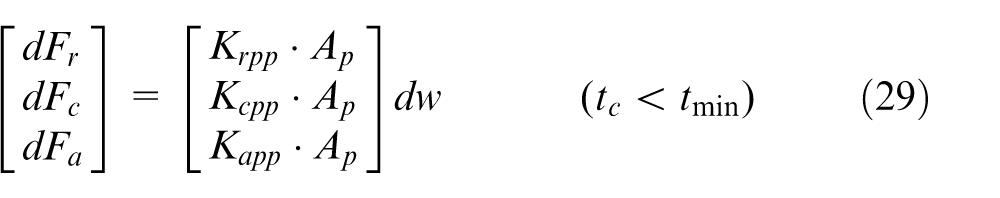
Equation (29) is decomposed into x, y and z directions. Forces of three directions are expressed as
Cutting forces of milling cutter during plowing-dominant regime cutting process by integral of infinitesimal cutting forces along cutting edge can be developed as follows
Equation (31) is the three-dimensional cutting forces prediction model when cutting thickness is smaller than the minimum cutting thickness. Three unknown quantities in the formula can be calibrated by slot-milling experiments.
Finally,
Cutting forces’ prediction model during micro-end milling of nickel-based superalloy process is testified by micro slot-milling experiment. Experiment conditions are as follows: two-flute flat end-milling cutter, diameter of milling cutter is 591.4 µm; rotating speed of spindle is 39,680 r/min; the extended length of tool is 20 mm; feed per tooth is 1.1 µm; axial cutting thickness is 35 µm; and runout calculated by prediction model of cutting-edge runout built in the previous section of the article is 11.65 µm. Measured cutting forces curve and cutting forces curve predicted by cutting forces’ prediction model during slot-milling process are shown in Figure 11.
Comparison of forces between experiments and simulations: (a) forces in X direction, (b) forces in Y direction and (c) forces in Z direction.
As shown in Figure 11(a), instantaneous cutting forces in X direction predicted by model match well with experiment measured values. The change law of the predicted forces and measured forces are basically same. As shown in Figure 11(b), the predicted cutting forces peak values in Y direction match well with experiment measured peak values, while main cutting force peak value of prediction model is a little smaller than experiment measured value. As shown in Figure 11(c), except that instantaneous predicted cutting forces peak values in Z direction match well with experiment measured peak values, other instantaneous cutting force values of prediction model are greater than experimental measured values. Judging from Figure 11, valley values of Y and Z directions are greater than experimental measured values. The experiment results verify that dynamic prediction of variation period of instantaneous cutting forces during micro-end milling of nickel-based superalloy process and peak values can be realized by three-dimensional dynamic cutting force prediction model during micro-end milling of nickel-based superalloy that is developed in this article.
Conclusion
Based on axial milling micro-hole experiments, the influences of extended length of milling tool and spindle speed on radial runout of cutting edge in micro-milling process are studied. Experimental results have shown that the minimum value of the radial runout of cutting edge is 8.97 µm. Based on the measurement results, the radial runout of cutting-edge model is built. Considering the radial runout of cutter, the single-tooth cutting phenomenon is analyzed according to the trochoid movement trajectory of micro-milling cutter, and the single-tooth cutting criterion is given. The single-tooth cutting phenomenon often appears in micro-cutting process. Considering radial runout of cutting edge, the nominal instantaneous undeformed chip thickness model and the calculation model of cumulative instantaneous undeformed chip thickness during the actual cutting process are established. Based on the minimum cutting thickness value, micro-end milling of nickel-based superalloy process is divided into two different cutting processes: shear-dominant regime cutting process and plowing-dominant regime cutting process. Moreover, cutting force prediction model during shear-dominant regime cutting process is developed based on the cutting force in proportion to cutting layer area, which takes the effect of plowing into account. Meanwhile, cutting force prediction model during plowing-dominant regime cutting process is developed based on the cutting force in proportion to interference volume between the flank surface of cutting tool and the workpiece. Comparison of cutting forces under different chip thickness models and experimental data indicates that the established instantaneous undeformed chip thickness model can be used to build cutting force prediction model, which can provide better cutting force prediction.
Footnotes
Declaration of conflicting interests
The author(s) declared no potential conflicts of interest with respect to the research, authorship and/or publication of this article.
Funding
The author(s) disclosed receipt of the following financial support for the research, authorship, and/or publication of this article: This research is supported by the Specialized Research Fund for the Doctoral Program of Higher Education under project number 20120041120034 and the Fundamental Research Funds for the Central Universities under project number DUT13LAB13. The financial contributions are gratefully acknowledged.