
Abstract
For a toroid-shaped end-milling cutter to have multi-structure features of tooth offset center and introversion of bottom edge, this article proposes a generalized parametric modeling method of the bottom edge, including a straight edge segment and a circular arc edge segment. And based on the parametric model, this article also deduces the corresponding tool path for grinding of the bottom edge’s rake and flank faces. The parametric modeling method is based on the geometric analytic equations while the grinding method is driven by the proposed parametric model and the parameters of rake and flank faces. The two methods can be applied to a bottom edge of a cutter with multi-structure features to guarantee G1 continuity at the two joints for connecting a circular arc edge with a straight edge and a conical helix edge, respectively. In order to verify the accuracy of proposed methods, experiments were carried out. The modeling and grinding experimental results verified the accuracy and utility of the methods.
Keywords
Introduction
Toroid-shaped end-milling cutter (TEMC) is widely used in manufacturing of complicated parts with free-form surfaces. 1 The main parts of cutting edges participated in milling are a straight edge, a circular arc edge and a conical helix edge shown in Figure 1. When compared with ball-end-milling cutter, TEMC has the advantages of high adaptability and machining efficiency under constant scallop height cutting, that is, TEMC allows a lower scallop height for a given step-over distance than that allowed by the ball-end one.2,3 In pinch milling of the turbine blades, TEMC can take wider passes than ball-nose end mills without increasing cusp height. And by keeping a TEMC normal to the surface during simultaneous five-axes machining, the machine can maintain constant cutting speed, thus result in faster metal removal and superior finish. 4 TEMC also has the ability to produce the periphery of parts meeting with the bottom floor with fillets. 5 Also, this type of cutter has higher material removal rate and lower flank wear rate because bottom edge is more solid,6,7 and thus, the machining quality is much more stable 8 compared with flat-end-milling cutter.
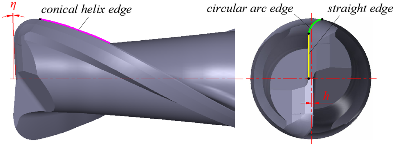
Main parts of cutting edges (straight edge has multi-structure features).
Generally, the straight edge on TEMC having a tooth offset to the bottom center can improve its strength, and introversion to reduce friction between bottom edge and machined surface. As shown in Figure 1, h is the tooth offset distance and η is the dish angle. Meanwhile, TEMC has smooth cutting edges to ensure the cutting continuity during machining. However, the multi-structure features lead to difficulties in parametric modeling and grinding. Although there is a complete set of theory that can be used to design and manufacture TEMC without multi-structure features at present, it cannot be applied directly to TEMC with multi-structure features. Therefore, the research on parametric modeling and grinding methods of this kind of TEMC is of great significance.
Precise parametric modeling of a bottom edge which determines the structure of end-milling cutter is essential for grinding of TEMC. Furthermore, the edge curve is also the guideline of the grinding wheel movement during grinding. Therefore, parametric modeling of a bottom edge must be studied first. Many scholars have done much research about it. Chen 8 adopted a supplementary cutting edge with a constant pitch to supply a general reference for TEMC with a constant angle between the cutting edge and the cutter axis. Chen et al. 9 presented a precise mathematical modeling procedure for the design of cutters with a circular arc edge, where the cutting edge forms a constant angle with the longitude curve, and presented systematically a design model of the involute end-milling cutter, where the cutting edge curve forms a constant angle with the cutter axis. 10 Chen et al. 11 presented a design model of TEMC, where the cutting edge forms an approximately constant angle with the cutter axis. Lin 12 proposed a geometrical model of the cutting edge on TEMC with a constant angle between the cutting edge and the cutter axis. Hsieh and Tsai 13 derived a mathematical model of the ideal conical helix edge which formed a constant angle to the longitudinal line at the toroid surface. Tang and colleagues14,15 studied the design models of the cutting edge with the convex curve generatrix and put forward three mathematical models, that is, planar cutting edges, helical cutting edges with a constant angle to the meridian and helical cutting edges with a constant pitch to avoid the problem of the inexistence of the cutting edge in the area near the end face of a cutter and the cutting edges are smoothly connected. Yang et al. 16 introduced the design of a cutting edge with equal pitch, and the edge was continuous at the joint of the circular torus and the cylindrical surface. Han et al. 17 gave the design method of the cutting edge which was defined as an approximate equal pitch curve with a concave arc as generator. Lv et al.18,19 established a mathematical model using infinitesimal geometry for the cutting edge design which used equal lead helix. By utilizing the principles of differential geometry, Wu deduced general mathematical models for the ball-end-type rotating cutter whose cutting edges can form a constant helical angle to the generatrix. And the grinding method of the basic groove mainly finished in one operation by two-axis numerical control (NC) machining in order to reduce the manufacturing cost is also provided. 20 Although Gao et al., 1 Gradišek et al. 21 and Wan et al. 22 used the generalized mathematical model proposed by Engin and colleagues,5,23,24 and seven geometric parameters were defined, if the circular torus is not a full quarter, there will be a discontinuity on the bottom edge. Cheng used the orthogonal helix edge curve as the S-shaped edge curve of ball-end-milling cutter, and the edge curve acquired based on the mathematical model proposed has a good S-shape and can connect with the circumferential edge curve smoothly. Furthermore, the model can be used easily to establish the S-shaped edge curve with or without tooth offset center. 25
Until now, several kinds of curves are used as a bottom edge on TEMC, such as an equal pitch edge curve, an equal helix angle edge curve with the longitude line, an equal helix angle edge curve with the cutter axis, a planar edge curve and an orthogonal helix edge curve. They have good edge curve shapes and can be used in series types of TEMC. However, present modeling methods using these kinds of curves are not concerned with a straight edge, not to mention the straight edge with multi-structure features, thus leading to complexity and difficulty of the grinding method. The grinding methods of TEMC are also studied by many scholars. Liu et al. 6 proposed a grinding process of the rake and flank faces and calculated the tool path and direction vector of grinding wheel. Chen et al. 9 obtained the sectional profile of the grinding wheel using an inverse problem-solving technique, and the manufacturing model presented can be used on a two-axis NC machine. Lin 12 provided grinding models of a section design, feeding speeds and relative position of the grinding wheel. Hsieh and Tsai 13 developed a systematic method for the grinding of the helical flute and the cutting edge, and considered the section profile and relative feeding velocities of the grinding wheel. Bao et al. 26 studied a virtual two-axis grinding model of TEMC with an equal helix lead cutting edge and an equal helix angle cutting edge, respectively.
In the above studies, many scholars focused on the parametric modeling and grinding methods of TEMC without multi-structure features of tooth offset to the center and introversion of the bottom edge. And thus, the existing research results are just in a limited scope of application of the methods presented and no unified model is formed. In order to meet the requirements of the design and manufacturing of a TEMC, especially its bottom edge has multi-structure features, this article presents a generalized parametric modeling method of a bottom edge, and based on this, a grinding method for the rake and flank faces of the bottom edge can make the cutting edges with G1 continuity, that is, (1) the cutting edge curves meet at the joint points and (2) their tangent directions at the joints are the same. The G1 continuity makes the composite cutting edge smooth. The modeling and grinding experiments indicate that the proposed cutter modeling and grinding methods can shorten the production cycle and improve the success rate of the design of a TEMC, thus reduce the cost of cutter production. Furthermore, the proposed general and parametric modeling of a TEMC has a great potential to support optimal cutter design for different machining applications, and the corresponding grinding method can easily realize the cutter design into tool manufacturing. This provides an integrated cutting design and manufacturing solution for wider applications.
This article is organized as follows: section “Parametric modeling method of bottom edge” describes the mathematical model of a bottom edge with multi-structure features of tooth offset center and introversion. Section “Grinding method of bottom edge” presents a grinding method of a bottom edge based on its three-dimensional (3D) mathematical model. The experiments and results are described in section “Experiments and results,” and finally, conclusions are drawn in section “Conclusion.”
Parametric modeling method of bottom edge
Among many kinds of curves mentioned above, the planar edge curve has a good curve shape and more simple mathematical computation compared with others. This type of edge curve can reach G1 continuity at the two joints of a circular arc edge with a straight edge and a conical helix edge, respectively, and the straight edge can have multi-structure features whether or not. So, planar edge curve is adopted, that is, the circular arc edge is the intersecting planar curve of the circular torus and the plane composed of an extended line of straight edge and a tangential line at the end of the conical helix edge.
As shown in Figure 2, the revolving surfaces of the cutting edges on TEMC are defined as three parts: a circular truncated conical surface A where the conical helix edge a lies, a circular torus B where the circular arc edge b lies and a concave conical surface C. Their relationship is that B is tangent with A and C. Straight edge c has the multi-structure features of tooth offset center and introversion.
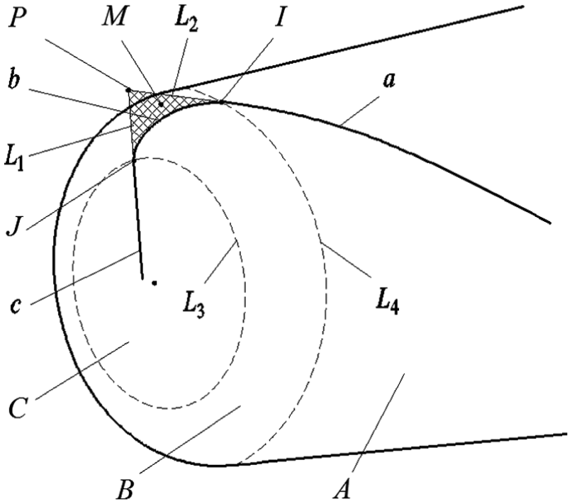
Relevant geometrical elements of bottom edge.
Define I as the intersection of a and b and J as the intersection of b and c. Define L1 as the extended line of c, L2 as the tangential line of a at I, L3 as the intersecting line of B and C and L4 as the intersecting line of A and B. Define P as the intersection of L1 and L2. Plane M is composed of L1 and L2. The bottom edge consists of b and c.
Parametric model of edge c
To reduce the complexity of mathematical modeling, define the coordinate system [O1-X1Y1Z1] as the first coordinate system, and the origin O1 as center of B. Z1 is the cutter axis, and the positive direction is from the cutter shank to the tip. X1 is parallel to the projection of c on the plane X1Y1. The point coordinates in the first coordinate system are identified by subscript _1.
Let γ be the angle between X1-axis and the projection of IO1 on the plane X1Y1. Rotate the first coordinate system on Z1-axis by angle γ negatively, and the coordinate system [O2-X2Y2Z2] is obtained as the second coordinate system. The point coordinates in the second coordinate system are identified by subscript _2. Then, the parametric models of c and b can be described in the second coordinate system.
As shown in Figure 3, define L as the intersection of L3 and the plane X1Z1, Q as the tip of C, K as the endpoint of c and Or as the center of the cross section of B on the plane X1Z1. Let re be the section radius of B, R be the distance between I and the cutter axis, κ be the half cone angle of A and β be the helix angle of a at I (angle between the helix edge on the revolving surface and the generator curve).
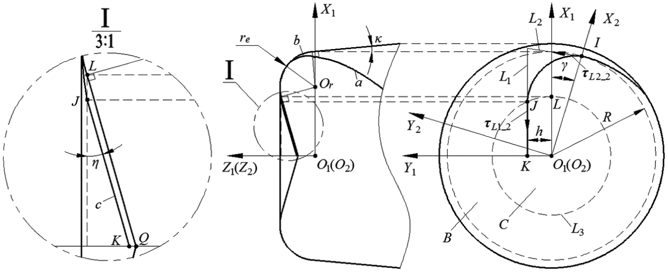
Schematic diagram for the design of edge c.
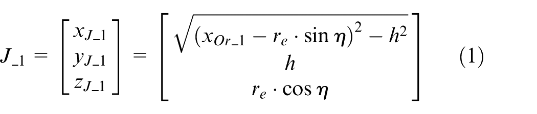
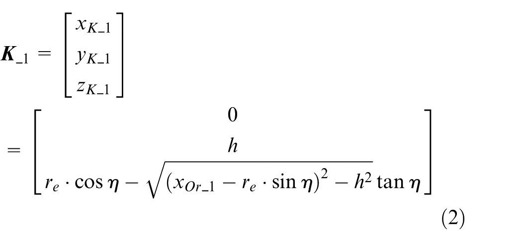
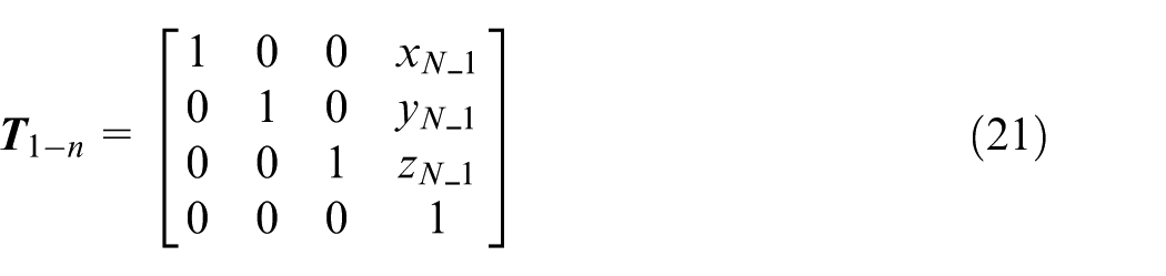
On the basis of cutter geometry relationship, the coordinates of J and K in the first coordinate system are as follows
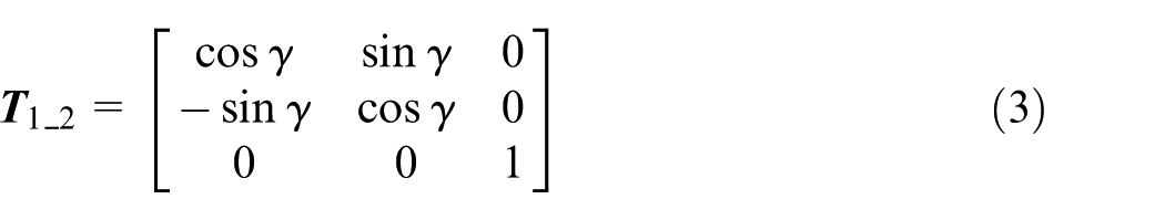
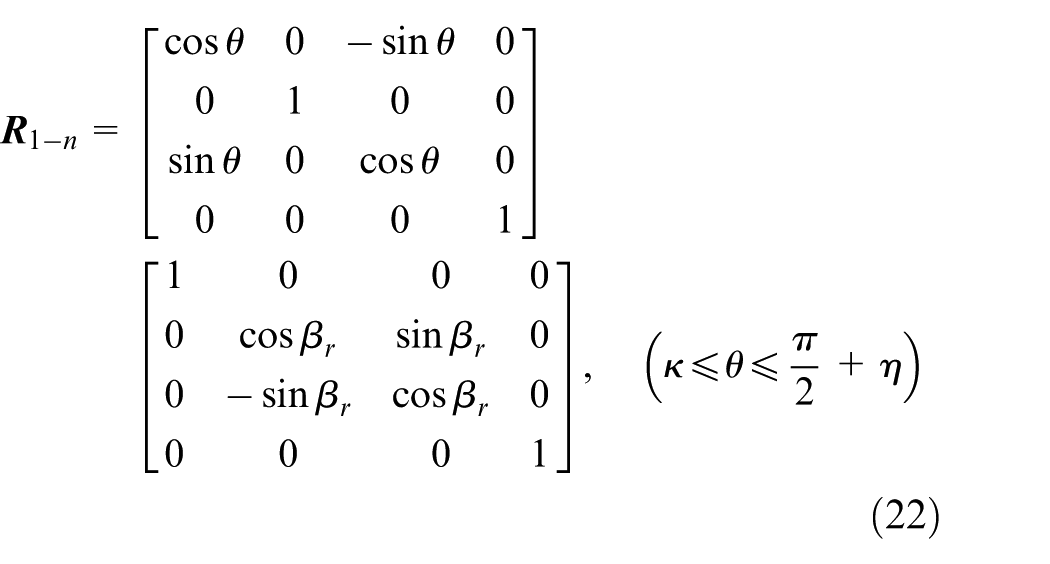
According to the direction of the coordinate system, the rotation transformation matrix from the first coordinate system to the second coordinate system can be expressed as follows
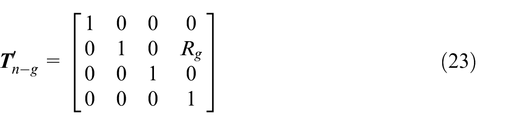
Obviously, the coordinates of I can be described as
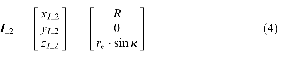
where:
Let
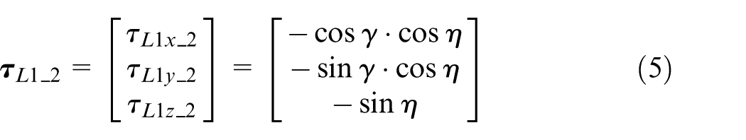
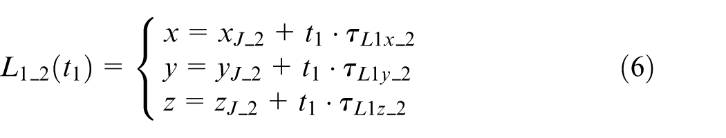
where t1 is the independent variable.
Similarly,
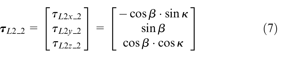
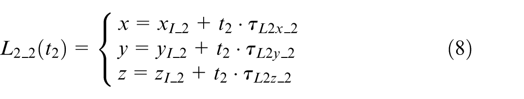
where t2 is the independent variable.
For L1 and L2 intersect at P, then
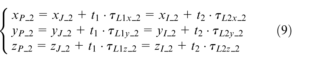
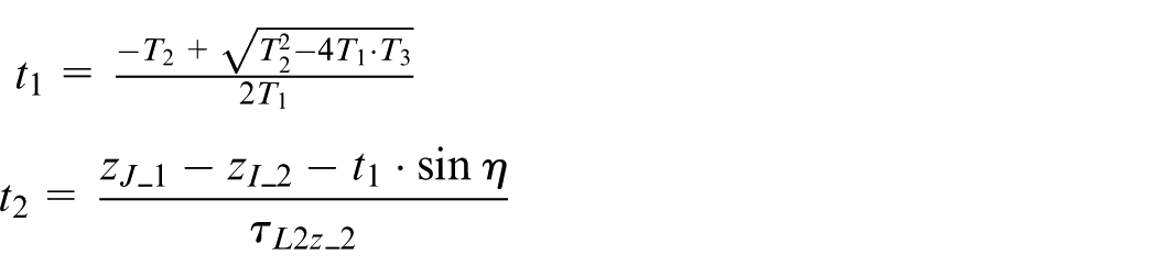
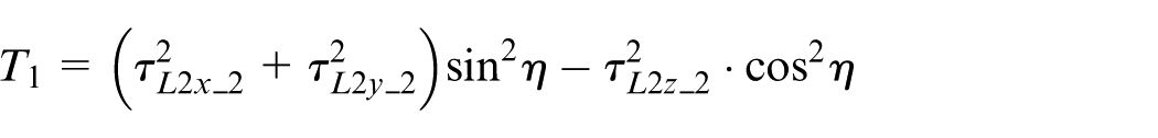
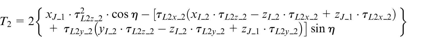
So, t1, t2 and γ can be obtained by equations (5)–(9), shown as follows
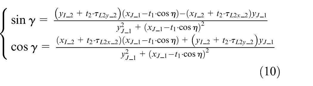
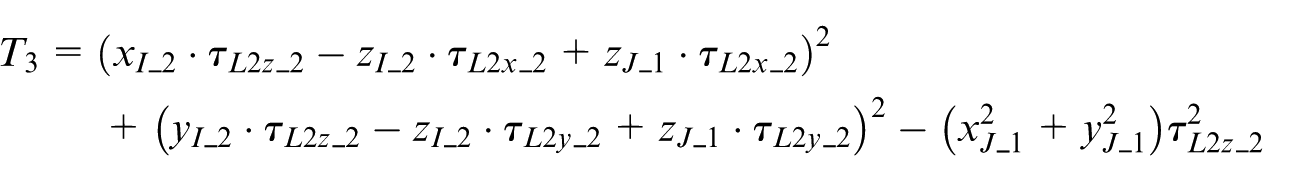
where
For c and L1 to be collinear, the unit direction vector
Parametric model of edge b
As shown in Figure 4, define E as an arbitrary point on B, E′ as the rotating projection of E on the plane X1Z1 and N as an arbitrary point on bottom edge. Let θ be the angle between E′Or and X1-axis (counter clockwise direction is positive) and ϕ be the angle between the projection of EO2 on the plane X2Y2 and X2-axis (clockwise direction is positive).
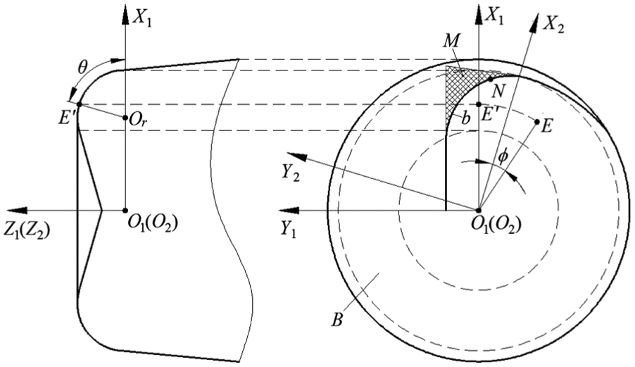
Schematic diagram for the design of edge b.
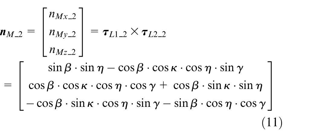
The normal vector
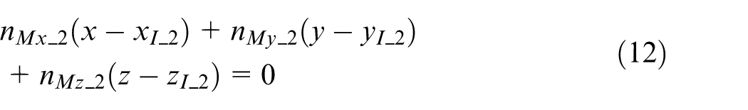
Hence, the equation of M can be obtained by equation (12)
By the definition of the circular torus, 27 the parametric equation of B can be written as

Since b is defined as a planar curve, b is the intersecting line of M and B and angle ϕ can be determined by equations (12) and (13)
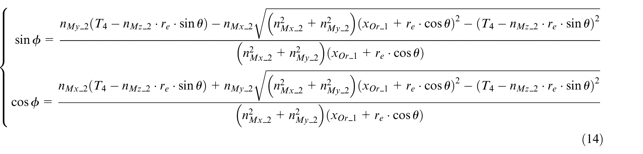
where
Substituting equation (14) into equation (13) gives the parametric equation b_2(θ) of edge b
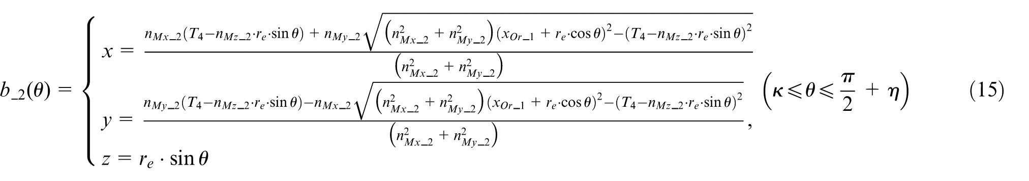
Taking the derivative of equation (15) with respect to θ, the unit direction vector
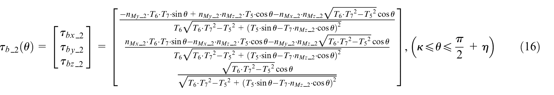
where
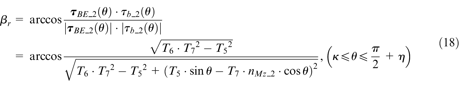
Generalized helix angle of edge b
The parametric model of edge b is already obtained. Although edge b is a planar edge curve, it can also be regarded as a curve with a variable helix angle. At present, the generalized helix angle on the revolving surface has two definitions: 28 one is the angle between the helix edge on the revolving surface and the generator curve, 25 and the other is the angle between the helix edge on the revolving surface and the cutter axis. 29 The first definition is considered in this article. The unit tangent vector of the generator curve of B at E can be expressed in the following form
Hence, the generalized helix angle at N can be given by
Parametric model of edge a
As shown in Figure 5, define F as an arbitrary point on a. Let φ be the angle between the projection of FO2 on the plane X2Y2 and X2-axis (clockwise direction is positive).
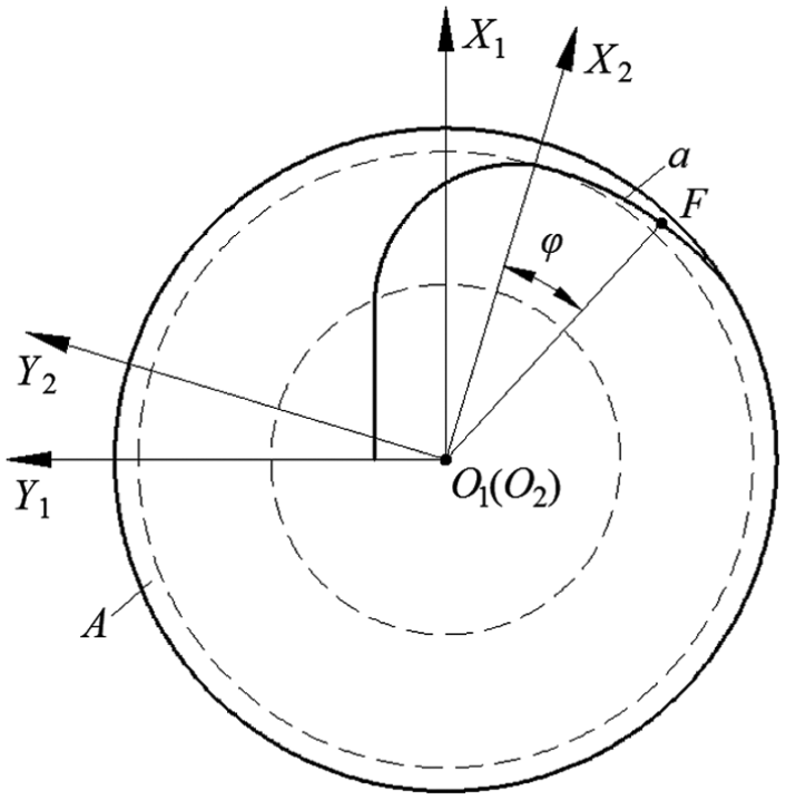
Schematic diagram for the design of edge a.
By the definition of the generalized helix, the parametric equation a_2(φ) of edge a can be written as
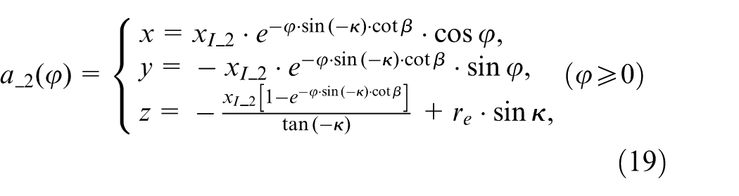
Taking the derivative of equation (19) with respect to ϕ, the unit direction vector
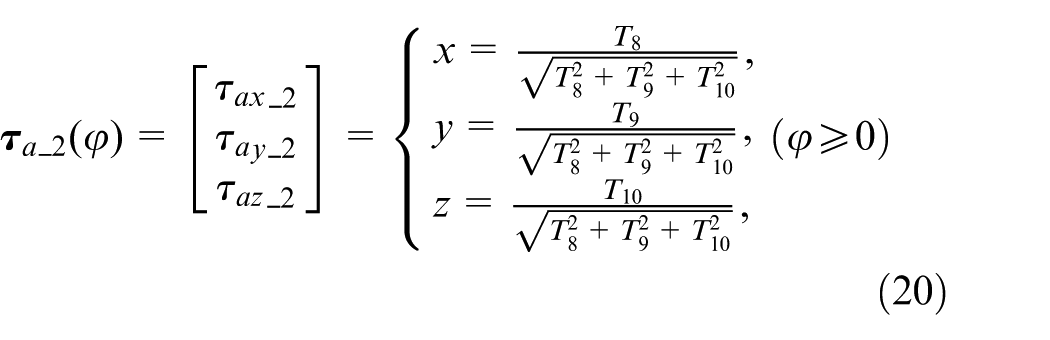
where
Grinding method of bottom edge
Parametric model of the bottom edge is the base of the tool path of the grinding wheel. Bottom edge is the intersection curve of rake face and flank face, and its structural parameters are guaranteed by the grinding process of the two faces. For TEMC to have a complex structure and lots of parameters and the purpose of the grinding method in this article is to guarantee the precision of parameters related to bottom edge, the detailed method of the section profile formation is not presented here for simplification purpose. For convenience, the tool path calculation is deduced in the first coordinate system, thus the origin of programming is O1 and grinding wheel wear is not considered.
Parameters of the grinding wheel
The profile of both V-shaped grinding wheel and cup-shaped grinding wheel can be defined by three parameters. Let Rg (the radius of the big-end of the grinding wheel), Hg (the thickness of the grinding wheel) and αg (the taper angle of the grinding wheel) be the three given geometric parameters of the grinding wheel profile, as shown in Figure 6.
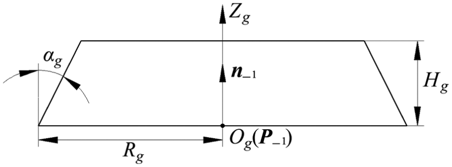
Geometric parameters of the profile of grinding wheel.
Define the coordinate system [Og-XgYgZg] as the grinding wheel coordinate system, the origin Og as the center of the big-end of the grinding wheel and Zg as the grinding wheel axis. Let
Grinding tool path for rake face
The grinding of the rake face of bottom edge is to form the chip-breaker-groove of the end cutting edge and the normal rake angle of TEMC.
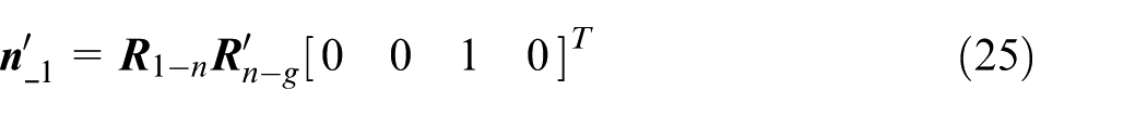
Define the coordinate system [On-XnYnZn] as the movable normal-section local coordinate system, the origin On coincides with N, Zn-axis is tangent to the bottom edge and the Xn-axis and the cutter axis lie in the same plane. In the grinding process, ν′ (the inclined angle restrained by the depth of chip-breaker-groove in rake face grinding) and γn (the normal rake angle of bottom edge) are pre-designed.
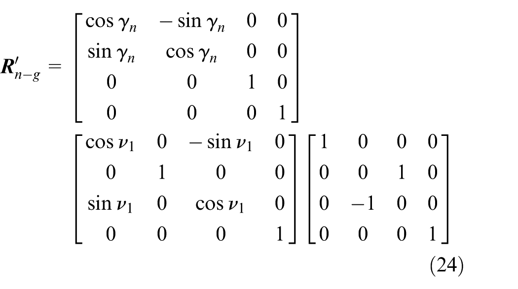
In a rake-face grinding process, the coordinate system [O′g-X′gY′gZ′g] can be obtained from the coordinate system [On-XnYnZn] by the following steps: rotate the coordinate system [On-XnYnZn] around Zn-axis by angle γn positively, then around Yn-axis by angle ν′ negatively, around Xn-axis by 90° negatively and finally, translate the rotated coordinate system from On to O′g to get the grinding wheel coordinate system.
Let
1. Vector of the grinding wheel axis.
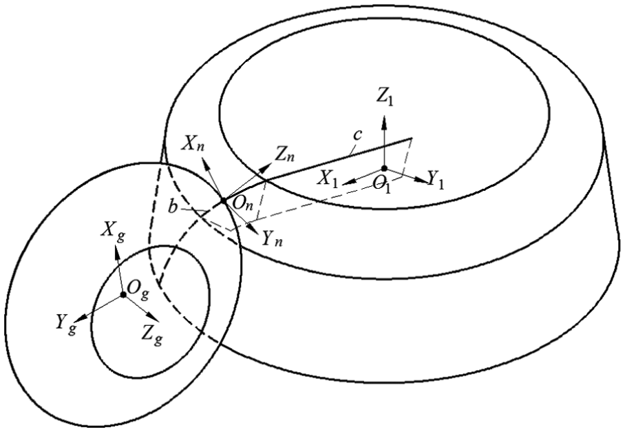
Schematic diagram of rake-face grinding.
According to the HTM theory, the vector of the grinding wheel axis in rake-face grinding can be expressed as follows
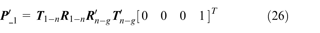
2. Position of CL point.
According to the HTM theory, the position of CL point in rake-face grinding can be expressed in the following form
Grinding tool path for flank face
The grinding of the flank face of bottom edge forms the normal relief angle of TEMC.
In the grinding process, ν″ (the inclined angle to avoid interference between grinding wheel and other tooth in flank-face grinding) and αn (the normal relief angle of bottom edge) are pre-designed.
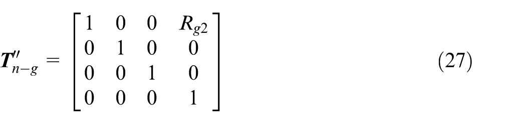
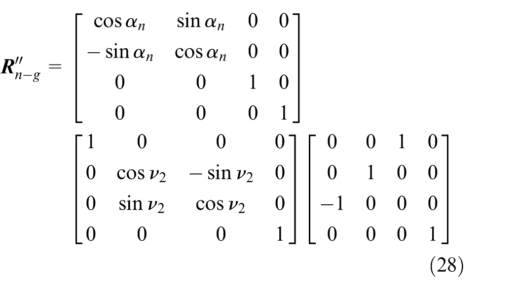
In a flank-face grinding process, the coordinate system [O″g-X″gY″gZ″g] can be obtained from the coordinate system [On-XnYnZn] by the following steps: rotate the coordinate system [On-XnYnZn] around Zn-axis by angle αn negatively, then around Xn-axis by angle ν″ positively, around Yn-axis by 90° negatively and finally, translate the rotated coordinate system from On to O″g to get the grinding wheel coordinate system for flank-face grinding.
Define
1. Vector of the grinding wheel axis.
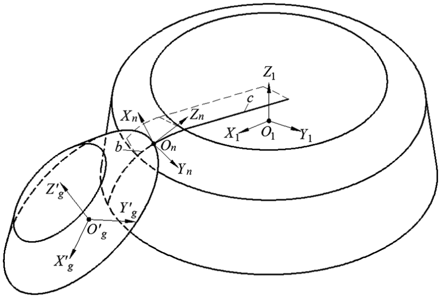
Schematic diagram of flank-face grinding.
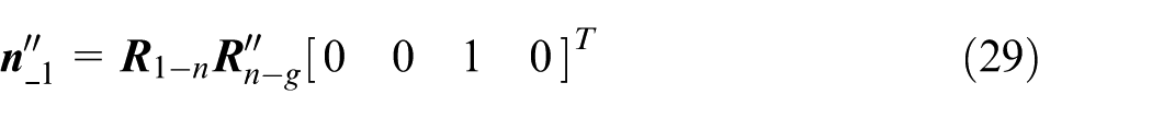
According to the HTM theory, the vector of the grinding wheel axis in flank-face grinding can be expressed as follows
2. Position of CL point.
According to the HTM theory, the position of CL point in flank-face grinding can be expressed in the following form
Experiments and results
Modeling experiment
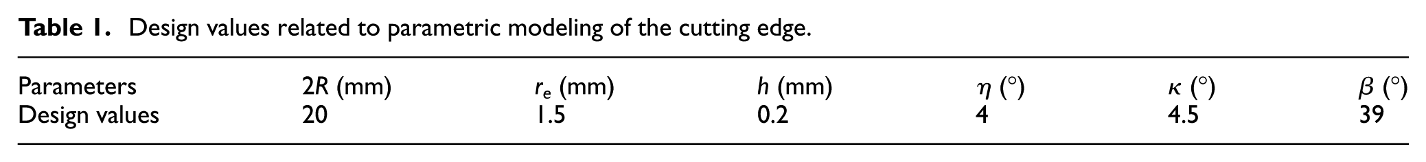
To verify the validity of the proposed parametric modeling method, modeling experiment was carried out in MATLAB. To validate the G1 continuity at the two joints of a circular arc edge with the connected straight edge and conical helix edge, one TEMC with multi-structure features of tooth offset center and introversion of its straight edge was taken for example. The design values related to parametric modeling of the cutting edge are shown in Table 1.
Design values related to parametric modeling of the cutting edge.
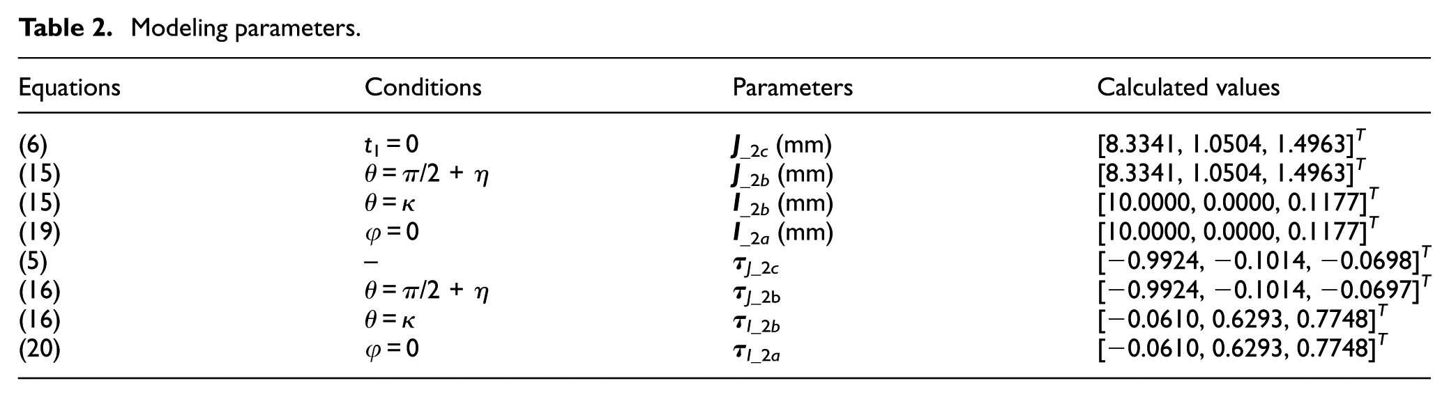
The calculated coordinates of J on c by substituting t1 = 0 into equation (6) is set as
Modeling parameters.
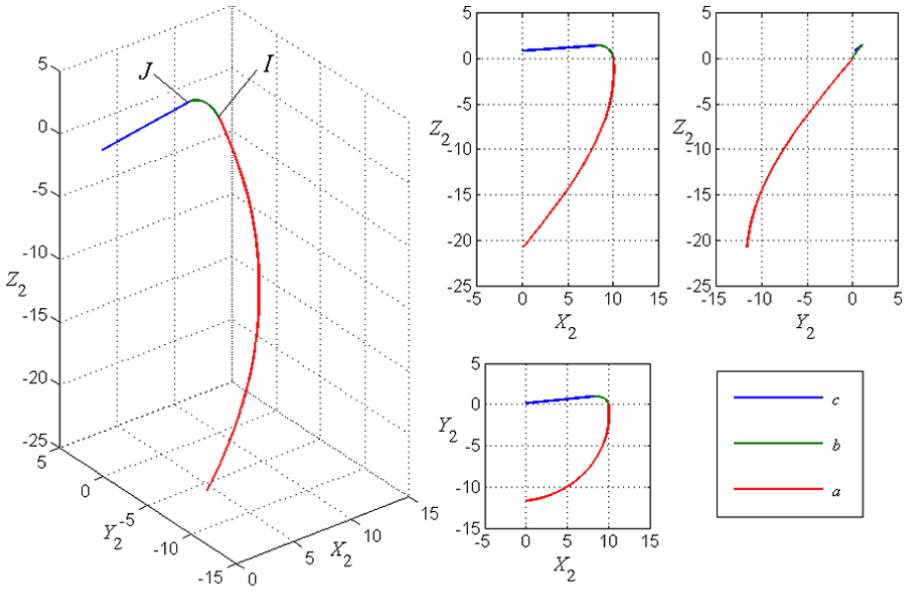
Modeling result of the bottom edge and the conical helix edge in MATLAB.
The calculated and modeling results validate the G1 continuity at the two joints and prove the accuracy of the parametric modeling method.
Grinding experiment
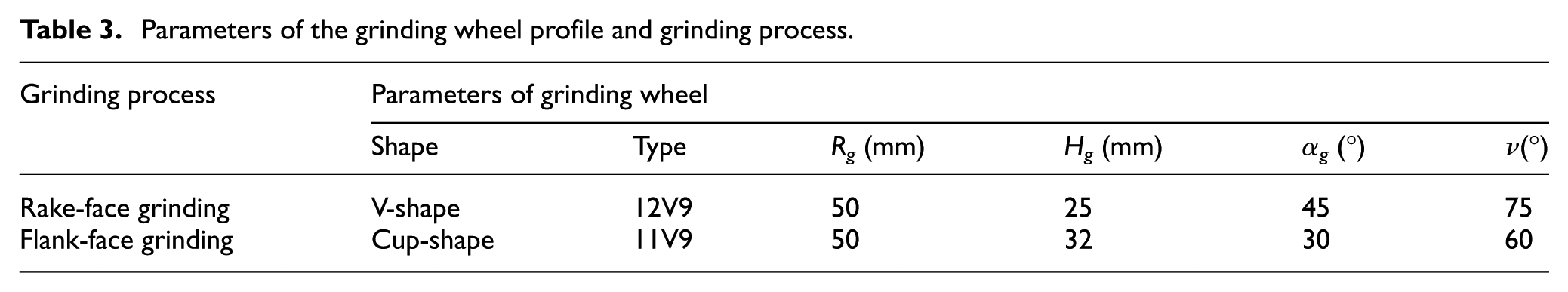
The machining accuracy of the grinding tool path was verified by the grinding experiment. The parameters of the grinding wheel profile and grinding process are shown in Table 3. The allowable absolute errors of machining are 0.1 mm/0.5°.
Parameters of the grinding wheel profile and grinding process.
Based on the mathematical models of TEMC, the grinding tool path in grinding of the tested TEMC was calculated by the grinding method put forward. Part of the grinding tool path file obtained by the grinding method put forward is shown as follows & GOTO/34.687784, −1.083085, −3.482481, −0.089849, 0.769583, −0.632194 GOTO/34.688929, −1.095449, −3.472860, −0.089220, 0.769622, −0.632236 GOTO/34.690062, −1.107808, −3.463239, −0.088592, 0.769661, −0.632276 GOTO/34.691183, −1.120164, −3.453619, −0.087964, 0.769700, −0.632316 GOTO/34.692292, −1.132515, −3.444000, −0.087335, 0.769740, −0.632355 GOTO/34.693389, −1.144862, −3.434381, −0.086707, 0.769780, −0.632393 GOTO/34.694474, −1.157205, −3.424763, −0.086079, 0.769820, −0.632430 GOTO/34.695548, −1.169544, −3.415145, −0.085450, 0.769860, −0.632466 GOTO/34.696610, −1.181879, −3.405528, −0.084822, 0.769901, −0.632502 GOTO/34.697659, −1.194210, −3.395911, −0.084194, 0.769941, −0.632536 GOTO/34.698697, −1.206536, −3.386296, −0.083566, 0.769982, −0.632570 &
The NC codes were generated by post-process from the grinding tool path and were verified in a grinding process. The material of TEMC was cemented carbide. The trial product grinded by ANCA FastGrind CNC cutter grinding machine tool is shown in Figure 10.
1. Measurement of the major parameters.
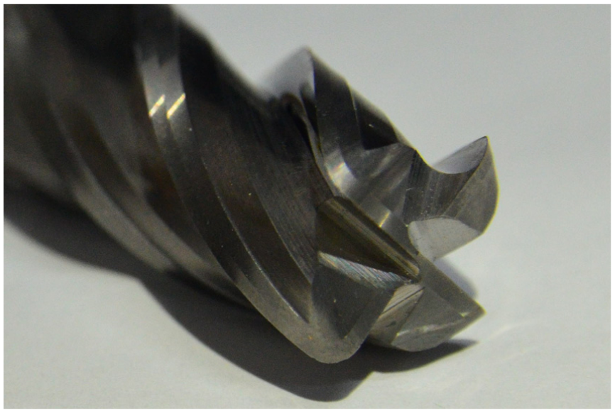
Trial product of TEMC.
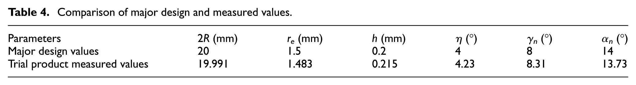
The major parameters of the trial product were measured by Zoller genius-3 tool measuring instrument using the principle of non-contact light perception scanning in no-vibration environment and at room temperature. In the “ELEPHANT” module of the instrument, choose the parameters which require measurement and then the instrument can automatically measure the parameters within the accuracy of 0.001 mm/0.01°. Measure the values three times over all different parameters and take the average as the final measured value to reduce measurement errors. The major design values and the corresponding trial product measured values are shown in Table 4.
Comparison of major design and measured values.
2. Measurement of the bottom edge.
The point cloud of the trial product was measured and obtained by Solutionix Rexcan III 3D optical scanner within the accuracy of 0.007 mm. The 3D optical scanning and the point cloud of the trial product are shown in Figure 11.
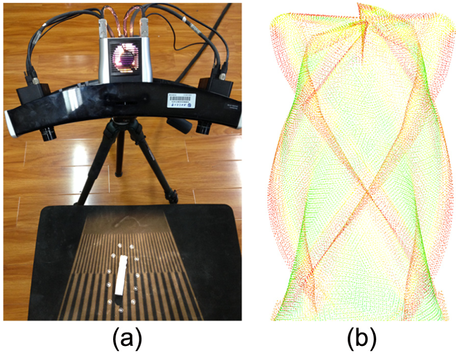
(a) 3D optical scanning and (b) point cloud of the trial product.
In total, 31 points on edge c and 12 points on edge b were extracted from the point cloud (see Figure 11). The extracted points and the theoretical bottom edge are built up in MATLAB as shown in Figure 12.
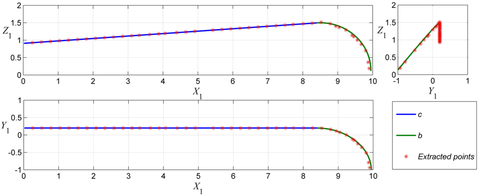
Theoretical bottom edge and the extracted points.
The coordinates of the extracted points were obtained, and the distances between the extracted points and the theoretical bottom edge were calculated. The maximum distances for edges c and b are 0.021 and 0.055 mm, respectively.
According to the measurement results of the major parameters on the bottom edge, the maximum absolute errors of the trial product grinded by the proposed grinding method are 0.055 mm/0.31°. And they are both within the allowable tolerance range. The precision of the major parameters and the edge position meets the requirement of machining, and the effectiveness of the tool path for grinding of the rake and flank faces of bottom edge is illustrated.
Conclusion
In this study, a generalized and accurate parametric modeling method and the corresponding grinding methods of a bottom edge of TEMC are presented. The bottom edge acquired based on this parametric modeling method can possess multi-structure features of tooth offset center or introversion. Furthermore, the parametric equations of the bottom edge are put forward, and the bottom edge can meet G1 continuity at the two joints of a circular arc edge with a straight edge and a conical helix edge, respectively. The grinding method is driven by the parametric model of the bottom edge and the design values of its rake and flank faces. And it can realize the accurate calculation of the tool path for grinding. Finally, the utility and accuracy of the parametric modeling and grinding methods are verified through a series of experiments.
It is believed that the proposed general and parametric modeling of the cutting edges of a TEMC with multi-features can be used to optimize cutter design for different application scenarios by setting up a proper set of parameters. Upon achieving the optimal cutter design, its corresponding grinding method is also ready to be applied effectively in the cutter (tool) manufacturing. Therefore, the integration, the cutter design modeling and the associated grinding method provide an integral solution for optimal cutter design and manufacturing.
Footnotes
Appendix 1
Declaration of conflicting interests
The author(s) declared no potential conflicts of interest with respect to the research, authorship and/or publication of this article.
Funding
The author(s) disclosed receipt of the following financial support for the research, authorship, and/or publication of this article: This work was supported by the Special Fund of High-end CNC Machine Tools and Basic Manufacturing Equipment (2015ZX04001002), China.