
Abstract
A double ball bar (DBB) is used extensively to evaluate the geometric and dynamic performance of three-axis machine tools by means of the XY, YZ and XZ planar circular tests. However, research using a DBB to test the rotary axes of five-axis machine tools simply, quickly and effectively is scarce. In this paper, a method having two steps to identify the imprecision of the rotary axes caused by the position-independent geometric errors (PIGEs) is presented for a tilting rotary type five-axis machine tool using a DBB. The first step is designed to evaluate two rotary axes with one setup. Its advantage of fast diagnosis effectively reduces the machine down time, and thus can be employed as a quick testing approach of the machine tool. However, if some of the diagnosed errors fall outside their tolerances, a more accurate but slower check needs to be carried out due to the limitation of the first step. The second step aims to test the two rotary axes separately, each in two sub-steps. By means of varying the position of the pivot, the A- and C-axes can be tested individually. Both steps are performed with only one axis moving, thus simplifying the error analysis. Implementation of the proposed methods was carried out on a Hermle C600U five-axis machine tool. To show the validity of the method, the identified PIGEs are compensated for in each step, which suggests that the first step can be used as a fast and preliminary indication of a five-axis machine tool’s performance, whilst the second can be carried out if a more thorough evaluation is needed.
Introduction
Background
Five-axis machine tools have been used extensively in modern manufacturing industry due to their advantages including improved surface finish, better material removal rate and minimal setups. 1 Most of the advantages are gained due to the two rotary axes in the five-axis machine tools, since they enable the orientation of workpiece with respect to the cutter, thus offering more flexibility when generating the cutter tool paths. 2 However, the two rotary axes introduce additional error sources to five-axis machine tools due to their geometric imperfections or faulty assembly. The total error budget of a five-axis machine tool (typical accuracy without numerical compensation) can be 100 µm or more. 2 Existing methods to measure linear axes in three-axis machine tools can no longer satisfy the demand of testing five-axis machine tools. Hence, measurement techniques for rotary axes are needed for maintaining the accuracy of five-axis machine tools.
Error categorization and measuring approaches
Flaws in machine tool components and joints downgrade the accuracy of five-axis machine tools. In order to identify the error sources, error categorization is carried out. Errors in five-axis machine tools are classified as geometric errors, thermally induced errors and dynamic errors. 1 Among these, geometric errors are the most significant factors influencing a machine tool’s performance. 3 They can be further classified as position-dependent geometric errors (PDGEs) and position-independent geometric errors (PIGEs).3–5 PDGEs result from defects in the machine components, thus are sometimes referred to as “component errors”. PIGEs are caused by the imperfections during the assembly process of the machine tool. They are often related to the location of each machine tool component and thus are known as “location errors”. 6 PDGEs are different from machine position to tool position, whilst PIGEs remain unchanged regardless of the positions of the axes. Due to the constant nature of PIGEs, it is easier to determine the values of PIGEs. Thus this paper examines the PIGEs of rotary axes, which are a major error source in five-axis machine tools. 3 The measuring approach is carried out on a tilting rotary table type five-axis machine tool. It is noted that the same method can readily be adapted to other types of five-axis machine tools.
Testing methods for rotary axes have been studied extensively in the recent past. They can be broadly classified as direct measurements and indirect measurements. Direct measurements refer to those dealing with single errors. Examples include using a dial gauge to indicate the run-out and concentricity of a rotary table. 7 A recent application using a laser beam as the testing reference gives a high accuracy evaluation (±1″) of rotary axes performance. 8 However, the direct measuring process may take several hours or even a day including a long setup time.
Indirect measurement methods work with motions involving the movement of multiple axes simultaneously to analyse machine tool accuracy. 2 Common indirect measurements include cutting tests and contour measurements. In the cutting tests, a specified test piece with particular geometries and shapes is machined on the CNC machine tool under test, followed by a detailed metrology investigation of the test piece. 9 The accuracy of this method is influenced by a number of factors including the machining condition, the accuracy of the metrological devices being used, tool wear etc., not just the geometric errors of the machine tool. Thus the uncertainty of the result may be greatly overestimated. Alternatively, to overcome the problems of actual machining, contour measurements with multiple axes moving simultaneously along a predefined path were developed. With the help of commercially available measuring equipment (R-test, 10 double ball bars (DBBs) 11 ), the error condition of the machine tool can be assessed.
The application of optical/laser techniques offer several measuring solutions for machine tools, however the measuring processes require a long setup time and the equipment requires a large initial investment. In order to shorten the machine down time and enhance measuring efficiency, simple, fast and cost effective methods are required for checking the rotary axes.
A DBB is able to measure one-dimensional length variation and is ideal for quick checking of three-axis machine tools by means of planar circular tests. 12 Due to the simplicity in structure and application, the equipment is employed in this study to investigate the PIGEs of rotary axes in a five-axis machine tool. Previous approaches to using a DBB to identify geometric errors include using simultaneous movements involving one rotary axes and two linear axes.13,14 Other methods include estimation of geometric errors for rotary axes by varying the DBB location and orientation.15,16 It has been suggested that a DBB is an ideal tool for fast machine diagnostic testing for linear axes. 17 However, there is a lack of simple and fast identification methods using a DBB to test the rotary axes. This paper evaluates the accuracy of a tilting rotary table of a five-axis machine in two steps using a DBB: the first step is preliminary but fast and the second is slower but detailed. New moving patterns for the DBB are proposed in the following sections. The rotary axes are measured with minimal setups and without additional fixtures, which is a major advantage over previously published methods.3,5,6 Approaches to minimize the setup errors in the spindle and the pivot tool cups are outlined. To deduce the PIGEs from the raw data, geometric models are developed. The contribution of the work is summarized in the final conclusion.
Machine structure and PIGEs of rotary axes
Five-axis machine tool
For most small and medium-sized five-axis machine tools, the two rotary axes are generally configured in one of three ways: a universal spindle head with two controlled axes, a swivel head with a controlled axis and a rotary table, and a tilting rotary table with two controlled axes.13,18Figure 1 illustrates the tilting rotary table type five-axis machine tools. Apart from the three Cartesian configured linear axes, X-, Y- and Z-axes, the combination table consists of two rotary axes, A- and C-axes, which rotate about the X- and Z-axes, respectively.
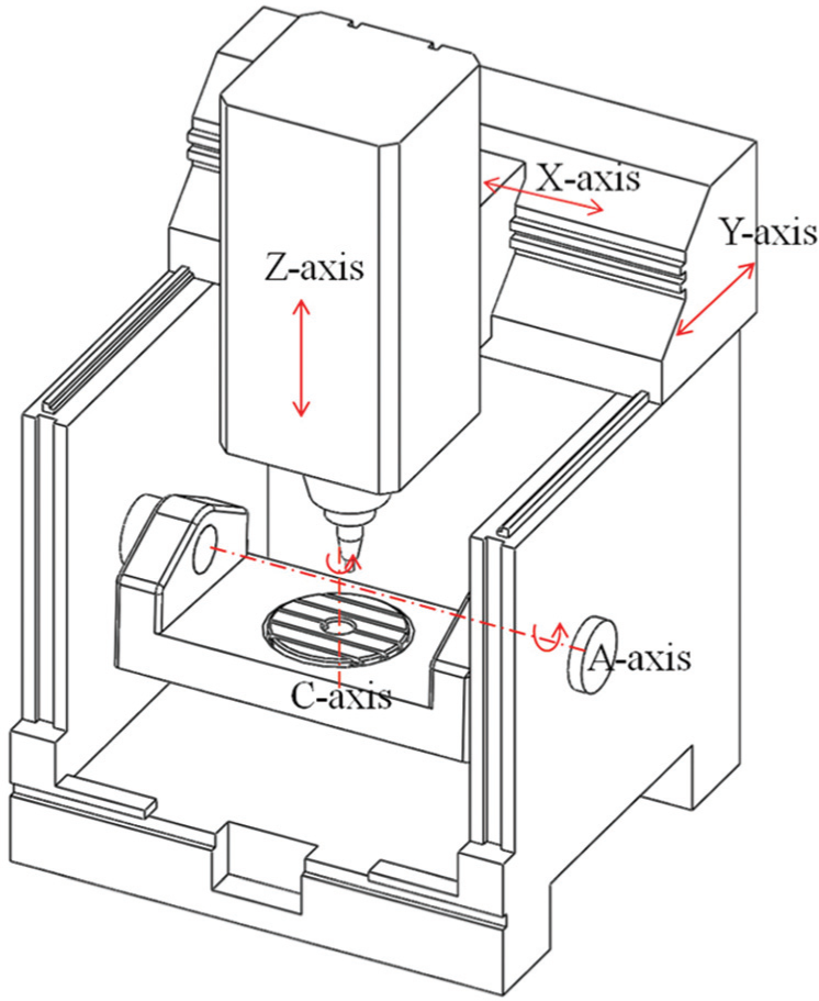
A schematic view of a tilting rotary table type five-axis machine tool.
DBB
Figure 2 shows a Renishaw QC20-W DBB. It comprises a linear displacement transducer with two magnetic balls at each end. During testing, one of the two balls is magnetized in the spindle tool cup in the spindle tool holder, whilst the other is attached to the pivot tool cup mounted on the table. The distance between the centres of the two balls is nominally 100 mm. The accuracy of the device is ±1µm and the resolution is 0.1µm when the ambient temperature is
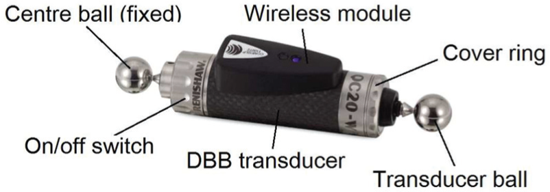
A Renishaw QC20-W double ball bar.
PIGEs of rotary axes
Each rotary axis has five PIGEs which are two position errors, two orientation errors and one zero position angular error
7
. Figure 3 illustrates the error composition of the C-axes. The position PIGEs are denoted as the letter “e” followed by a two character subscript, where the first character is a letter representing the direction of the error and the second is the axis of motion
5
. The orientation PIGEs are named with the same subscripts as the position PIGEs except that “e” is replaced by “
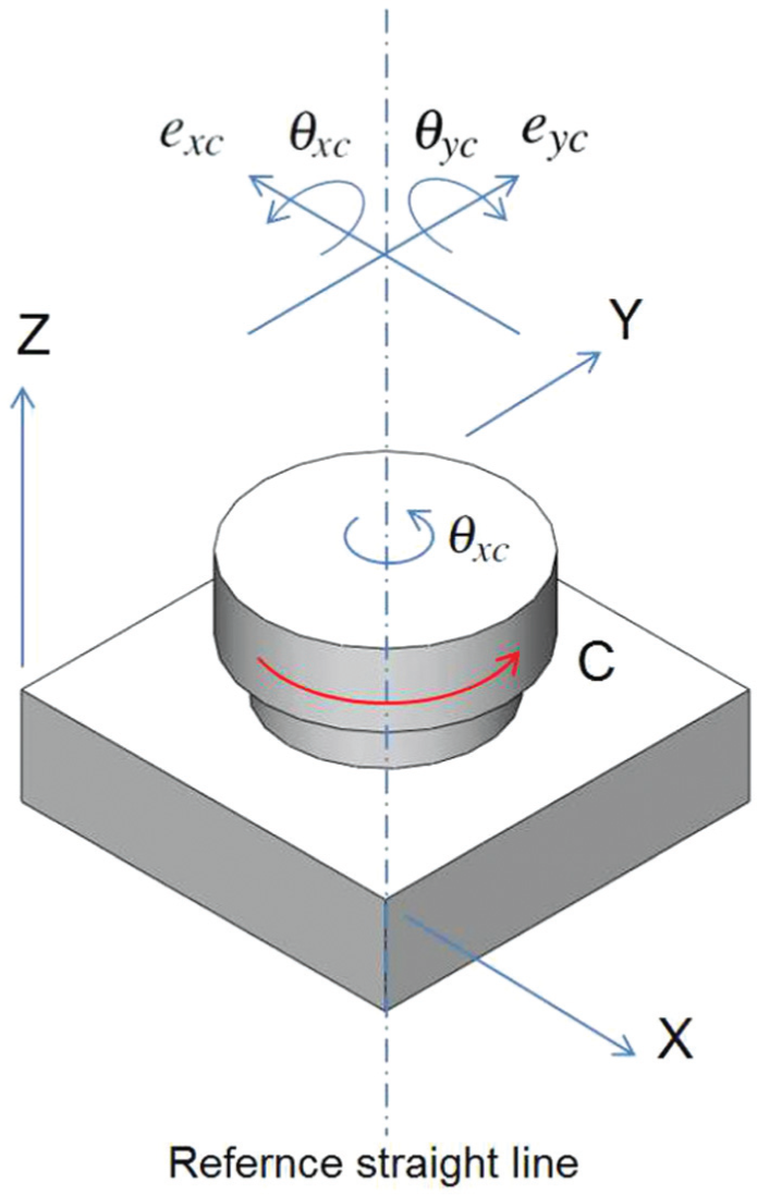
PIGEs of the C-axis.
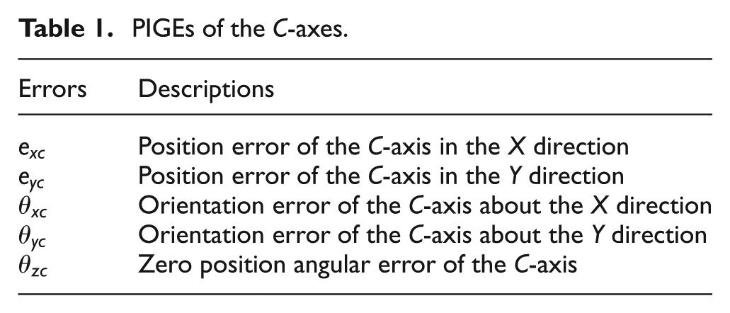
PIGEs of the C-axes.
When testing the geometric accuracy of a machine tool, the zero positions of linear axes can generally be set to zero. 7 Thus, four PIGEs for each rotary axis are considered. The reference straight line in Figure 3 is an associated straight line fitting the measured trajectory of points, and represents the actual condition of axes calculated using least squares.7,19
DBB measuring method
Two steps of the method are presented in this section, both formed of four sub-steps. In each step, only the rotary axis under test is driven, with the other four axes stationary. This will exclude errors of the stationary axes and simplifies the analysis process. All tests are carried out with the assumption that the linear axes are within tolerance and hence will not result in significant errors. This is based on the fact that current CNC controllers are good at compensating for the geometric errors of linear axes but not for those of rotary axes. 11
The reference coordinate system (RCS) needs to be defined first for explaining different positions in the tests. The origin of the RCS is located at the intersection of the nominal A- and C-axes. The directions of the three axes are parallel to the machine X-, Y- and Z-axes, respectively (Figure 1).
DBB installation and initial error elimination
Figure 4 depicts how the DBB and its accessories are placed on a five-axis machine tool. The spindle ball of the DBB is magnetized in the spindle tool cup and the table ball is attached to the pivot tool cup mounted on the tilting rotary table.
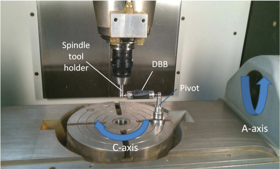
Installation of the DBB located on a five-axis machine tool.
The raw data collected from the DBB tests is the length deviation and needs to be converted into coordinate values in the corresponding local coordinate systems (LCSs) for later analysis. However, the DBB balls might deviate from their desired positions due to the setup errors induced by the fastening processes at the spindle and pivot. Therefore, after setting the pivot and the spindle tool cups, measurements and adjustments are carried out to minimize the errors in the placement of the tool cups. A dial indicator is used to adjust the spindle tool cup to ensure its centreline aligns with the main spindle axis. Since the runout in the horizontal directions directly affect the accuracy of test results, 3 it should be controlled within the machine tolerance (±1µm). The vertical position of the spindle tool cup does not require calibration since it is clamped in the spindle tool holder before setting the datum. To measure and adjust the pivot position, the conventional DBB tests in the XY and YZ planes around the pivot are conducted to obtain the deviations between the ideal and actual positions of the pivot. 17 The captured deviations are used for further position corrections. The XY planar test is taken as an example to show the process of eliminating the initial position error in the X and Y directions.
Let
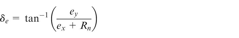
where
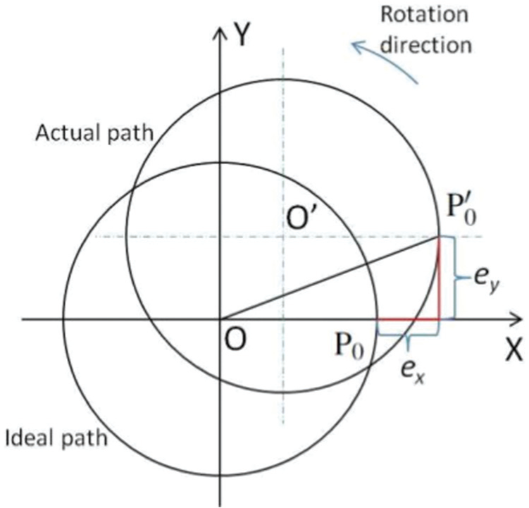
Elimination of errors caused by inaccurate pivot position.
Step 1
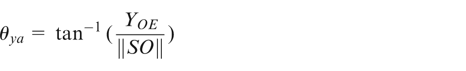
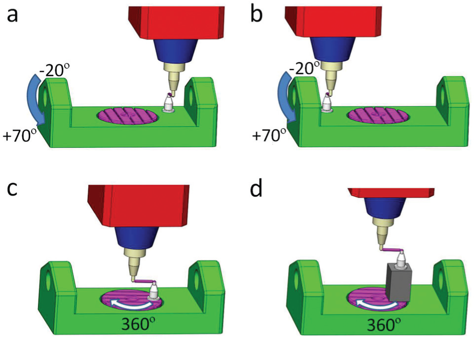
In this step, the A- and C-axes are both examined in two sub-steps (a) and (b), shown in Figure 6. For the A-axis: in sub-step (a), the DBB is placed with one ball in the spindle tool cup at the origin of the RCS and the other ball in the pivot tool cup away from the nominal C-axis by a distance of
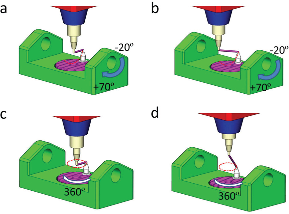
Four sub-steps of the first step. (a) A-axis test without an extension bar. (b) A-axis test with an extension bar. (c) C-axis test without an extension bar. (d) C-axis test with an extension bar.
In sub-step (b) in Figure 6, the DBB length is extended by 50 mm using an extension bar. To fit the 150 mm DBB, a displacement of the spindle tool cup in the negative X direction is applied (Figure 6(b)). The same tilting angle of the A-axis from
For the C-axis: in sub-step (c), the C-axis rotary table rotates through a
In sub-step (d), the C-axis table rotates through
Error analysis of step 1
Sub-steps (a) and (c) use the DBB to measure the centre offsets of the circular trajectory (red dotted arcs or circles in Figure 6(a) and (c)) from its nominal centre. Using the method given in Jiang and Cripps, 11 the position errors for both axes are determined using least squares.
Table 2 lists the errors included in each sub-step, where
Errors included in each sub-step of step 1.
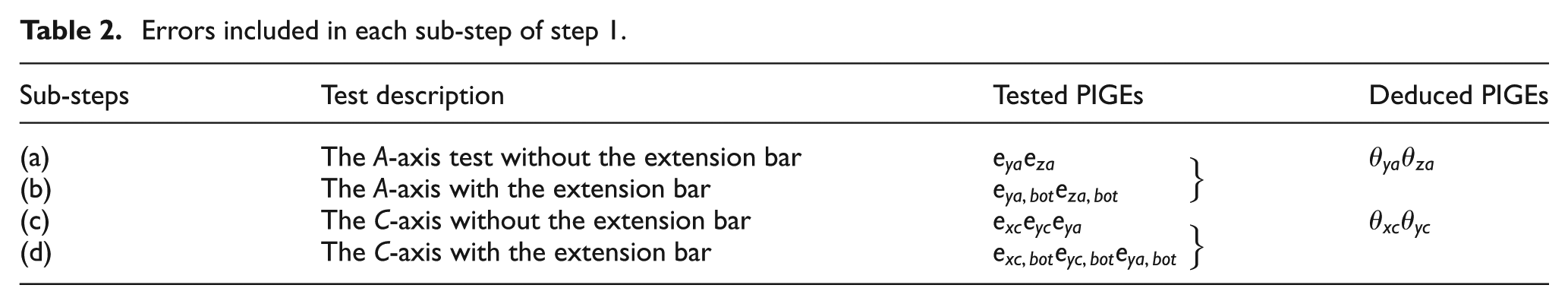
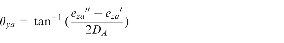
For sub-steps (b) and (d), the extension bar is applied to make the orientation PIGEs evident. Sub-step (b) which is the A-axis test with the extension bar is explained herein. The same model can be adopted in sub-step (d).
An exaggerated diagram to illustrate the errors of the A-axis is given in Figure 7. The centre offsets calculated in sub-step (a) is denoted as OP, where the point O is the ideal centre of rotation whilst the point P is the offset centre due to the position PIGEs. With the extension bar, the spindle ball is moved to point S, which is lying on the nominal A-axis. The length of SO can be determined from the length of the DBB and the distance from the pivot centre to the nominal A-axis using Pythagoras theorem. Figure 8 shows the setup with the extended DBB when the A-axis tilting table is set to zero. In order to transfer the captured lengths
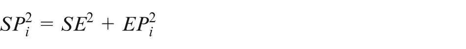
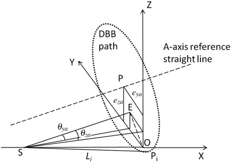
A geometric model for the orientation errors in the A-axis test with the extension bar.
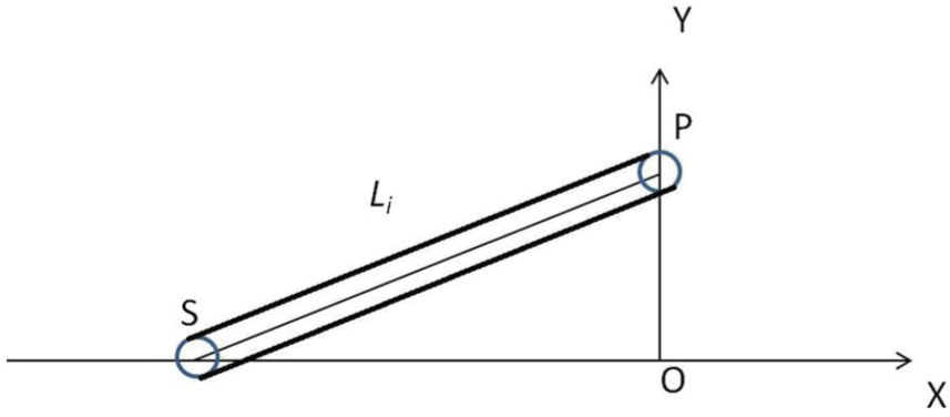
Calculation of the length of SO.
Expressing
Since SE is normal to the bottom plane hence parallel to the A-axis reference straight line, the orientation errors of SE are the same as those errors of the A-axis reference straight line. Therefore, the orientation errors
where
Measurements without the extension bar indicate that
As explained previously, the first step can help to identify the position and orientation PIGEs of the A- and C-axes. However, the vertical straightness errors and the positioning variability of linear axes may affect the accuracy of the results. Relevant research indicates that the above causes can result in loss of accuracy of the tests.3,5 This can be explained from the perspective of the linear guideways. For most of the five-axis machine tools, the central part of the sliding guideway is more likely to be used and the wear profile is modelled in the form of a normal distribution. 20 Using the central part of the linear guideway to place and measure the pivot may induce additional errors. In order to test the A-axis more accurately, the next step can be implemented as a supplement to check the rotary axes more accurately.
Step 2
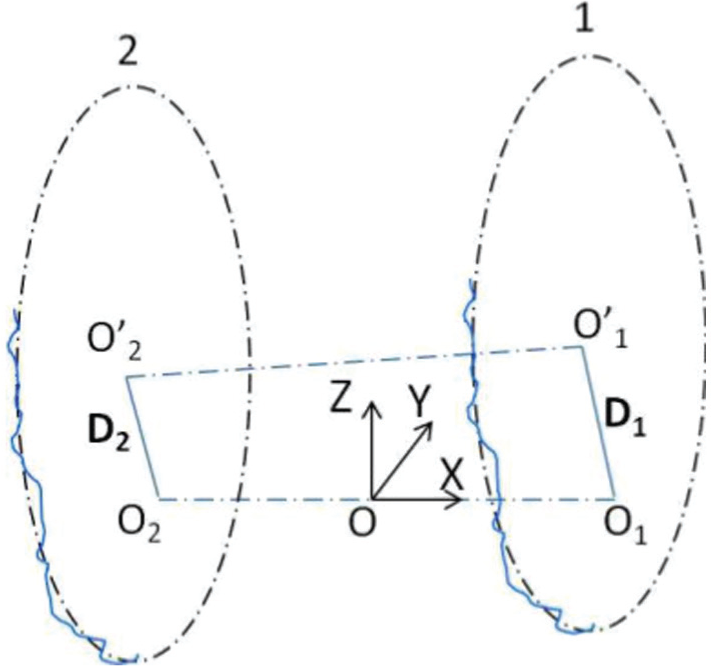
In this step, each rotary axis is tested individually with two different setups. Again this step is divided into four sub-steps, two for each axis, as depicted in Figure 9. In the A-axis tests, two positions 1 and 2 (Figure 9(a) and (b), respectively) which are symmetric with respect to the YZ plane of the RCS are chosen for the pivot. According to Lee and Yang, 3 larger distances between the two positions is recommended to improve the uncertainty of the measurement. Therefore, the positions 1 and 2 are chosen to be as close as possible to the two sides of the A-axis tilting table, with the consideration of collision avoidance between the spindle and the table. The pivot is attached to the A-axis tilting table away from the origin of the RCS. The centre of the spindle tool cup is aligned with the A-axis, having the same X coordinate as the pivot centre. During both measurements, the spindle ball is kept stationary and aligned with the nominal A-axis, whilst the table ball rotates with the A-axis table about the A-axis. Only the A-axis rotates during testing, which effectively excludes errors of stationary axes.
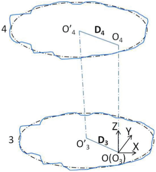
Four sub-steps of step 2. (a) Position 1 of the A-axis test. (b) Position 2 of the A-axis test. (c) Position 3 of the C-axis test. (d) Position 4 of the C-axis test.
Positions 3 and 4 (Figure 9(c) and (d), respectively) are the C-axis tests with different Z heights. The spindle ball and the table ball are positioned with the same height above the C-axis table in both sub-steps. The table ball rotates with the C-axis table and the centre of the spindle ball is kept stationary, aligned with the C-axis. For the position 4, when the height block is used, the spindle is close to its upper limit. A larger distance between positions 3 and 4 is not possible.
As the accuracy of both tool cups are error prone, calibration of the tool cups are conducted after setting the pivot positions. Since the tool cup fixed in the spindle tool holder remained unchanged, the distance from the tool cup centre to the Z-axis zero position was ensured accurate, as explained in Jiang and Cripps. 11 Also the axis of the tool cup centreline and the rotational axis of the spindle was measured and adjusted to be within tolerance. In terms of the centre pivot position, conventional DBB measurements are carried out to determine the deviations in the Y and Z directions of the A-axis tests and deviations in the X and Y directions of the C-axis tests, respectively.
Error analysis of step 2
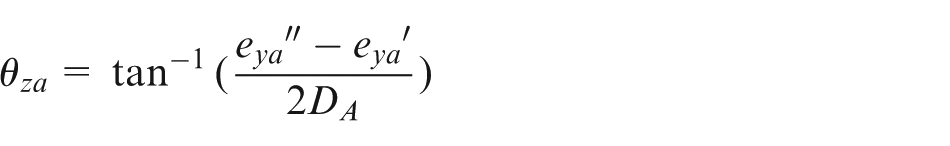
The planar circular tests are conducted to measure the centre offsets of the four circular trajectories at the four positions given in Figure 9. The centre offsets, namely the local position PIGEs, are not completely identical to those measured with respect to the RCS due to the influences of the orientation PIGEs. Since the reference straight lines of the rotary axes do not rely on the coordinate system chosen, the orientation PIGEs are the same regardless of the testing position. The relationships between the local position PIGEs and the ones measured in the RCS can be expressed as

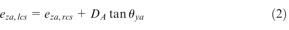
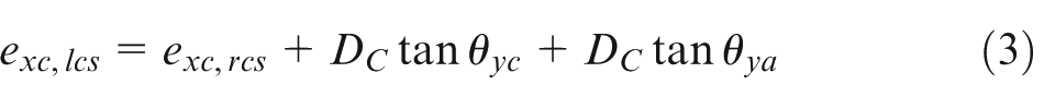
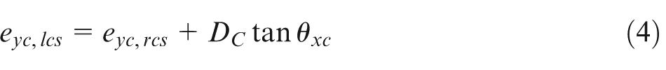
where the subscripts “lcs” and “rcs” indicate the position PIGEs are expressed with respect to the LCS and RCS, respectively. Here
where
The two trajectories of the A-axis tests at positions 1 and 2.
The two trajectories of the C-axis tests at positions 3 and 4.
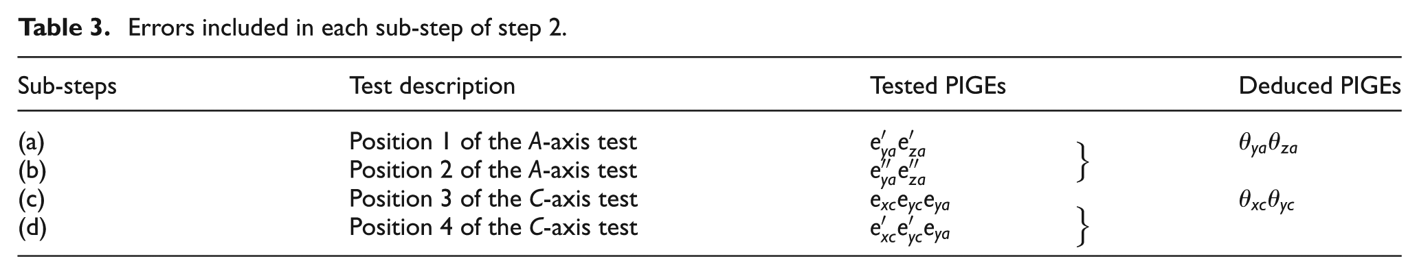
Errors included in each sub-step of step 2.
In Figure 11, the ideal C-axis passes through the origin of the RCS
where
Experiment results and discussion
Both steps of the method were carried out on a Hermle C600U five-axis machine tool for validation purposes. The testing specifications are listed in Table 4.
Specification of both steps.
A 20 min warm up of the machine tool is carried out before each test according to the Test code for machine tools. 7 Each test takes approximately 30 min (including the set-up process of 10–15 min).
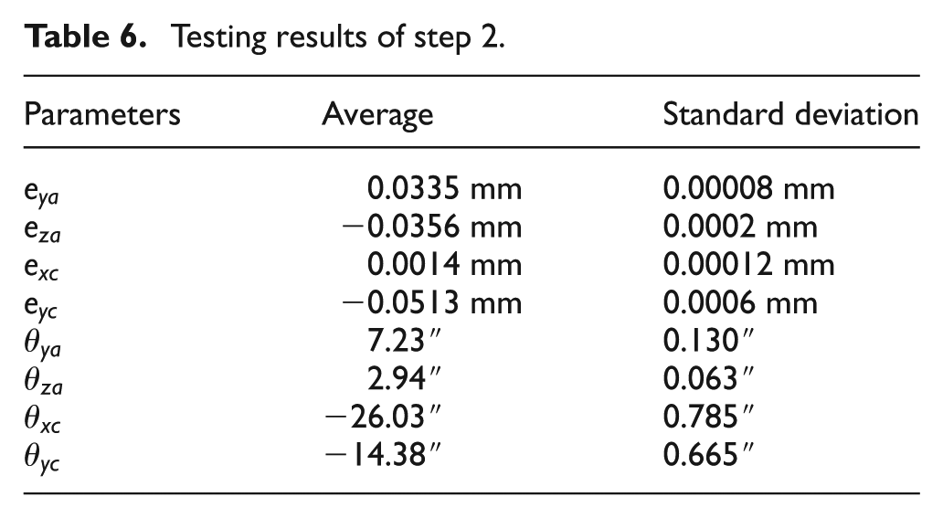
The two steps were repeated until the repeatability was within the tolerance (±1µm for position PIGEs and ±1″ for orientation PIGEs). 11 Averages and standard deviations of all results are calculated based on the repeatability tests, given in Tables 5 and 6. The position PIGEs identified by both testing methods are close and within tolerance whereas the results of orientation PIGEs differ from each other. The two tests both use the centre offsets captured in circular tests to calculate the orientation PIGEs. The difference between the local centre offsets of the same axis in different sub-steps is less than 2 µm. Considering the straightness errors and positioning variability of the linear axes as well as the DBB measuring uncertainty (±1µm), the two centre offsets may fluctuate within their tolerances thus resulting in the disagreement of the orientation errors obtained in the two steps. 3
Testing results of step 1.
Testing results of step 2.
Figures before and after compensation of the A- and C-axes are given in Figures 12 and 13 to show the effectiveness of the proposed method. After compensating the determined PIGEs for the corresponding axes, the accuracy of both rotary axes are improved and residual errors are controlled within tolerance (±1µm).
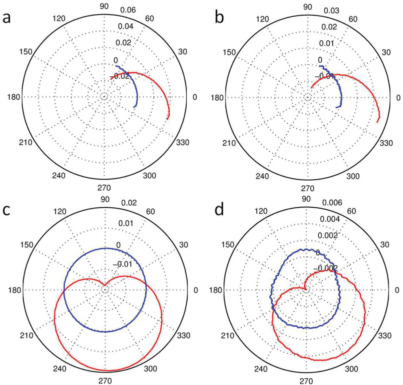
Step 1 results with (blue) and without compensation (red) (mm).
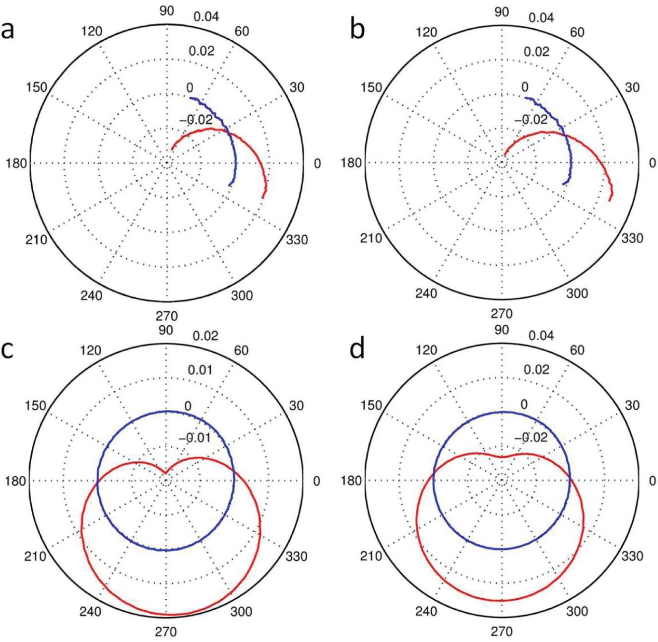
Step 2 results with (blue) and without compensation (red) (mm).
The first step is ideal for simple and fast measurements of rotary axes of five-axis machine tools. When using the first step to measure the rotary axes, only one setup is needed during testing, thus greatly improving the measurement efficiency. The measuring process does not include simultaneous motions of multiple axes, thus simplifies the error analysis.
The second step also uses the idea of only having the rotary axis move under testing, while keeping the other four axes stationary. Also, the second step avoids the most worn part of the linear guideways, thus offering a better accuracy 20 . Figures 12 and 13 both show similar improved error identification in corresponding axes: the machine tool is controlled within tolerance if the determined PIGEs are compensated. Step 1 is a fast solution of diagnosing the machine tool condition with only one setup. If the results of step 1 stay within predefined tolerances, no further testing is required. Step 2 can be carried out if one would like to gain more confidence about the test results of step 1.
Conclusions
A testing method using a DBB comprising two steps has been presented to determine the PIGEs of the rotary axes of a tilting rotary type five-axis machine tool with new testing paths. Both steps consist of four sub-steps: two for each rotary axis. For the first step, without changing the pivot position, the two rotary axes are examined. With a 50 mm long extension bar, measurements can be carried out simply and quickly. If the results of step 1 show that the errors are outside of the desirable tolerance, the second step can then be carried out. This is due to the fact that the second step can effectively avoid using the most worn part of the linear guideways, thus giving a better condition for testing the accuracy. Different positions of the pivot are chosen to obtain the position and orientation PIGEs.
One advantage of the method is the rotary axes are driven individually. Therefore, the analysis of PIGEs is simplified. Also, no additional fixturing is required, thus simplifying the setup process. The accuracy of the spindle tool cup is adjusted using a dial indicator, whilst the errors in the placement of the pivot tool cup are measured by the conventional planar circular tests using a DBB. Both steps were validated on a Hermle C600U five-axis machine tool. Before and after compensation of the method are given to indicate its effectiveness. The first step can be employed as a quick diagnosis since it indicates the machine condition within a few minutes. Whilst the second step can be carried out if a measurement with higher precision is required. The results of the second step may indicate the machine tool is out of tolerance, then a more detailed but time-consuming check has to be conducted. It is suggested that the method can be used as a form of regular test of machine accuracy of five-axis machine tools.
Footnotes
Declaration of Conflicting Interests
The author(s) declared no potential conflicts of interest with respect to the research, authorship, and/or publication of this article.
Funding
The author(s) disclosed receipt of the following financial support for the research, authorship, and/or publication of this article: This work is supported by the Chinese Scholarship Council (grant number 2011646018) and University of Birmingham (grant number 1107583/57-7716).