
Abstract
In five-axis machining, stability of the machining process is determined not only by the combination of depth of cut and spindle speed but also the cutter postures (orientations). In this article, we propose to construct posture stability graphs to guide the selection of cutter postures during tool-path generation. Posture stability graph provides a partitioning of the allowable range of cutter postures, dividing it into stable and chatter zones. Using postures only from the stable zone, we can achieve chatter avoidance without the trouble of tuning other process parameters like spindle speed. Posture stability graphs are constructed by identifying the cutter orientations that would render the machining system borderline stable under the given machining conditions. These postures would make the boundaries between stable and unstable zones on the posture stability graph. Such a process is achieved by modelling the machining system as a 2-degrees-of-freedom spring-mass-damper system and applying the full-discretization method for chatter identification. Many experiments have been carried out, based on which the effectiveness of the posture stability graph approach has been verified.
Keywords
Introduction
Possible existence of machining chatter is a key adverse factor that affects the surface finish quality for all machining processes. Chatter is a kind of self-excited and regenerative vibration, usually caused by lack of stiffness of the machining system, made of the cutter, holder, workpiece, and the machine tool itself.1–3 Much research4–11 has been done regarding the mechanism of chatter, which shows that a bad combination of spindle speed and depth of cut would trigger chatter in three-axis machining. Stability lobe diagram (SLD) has since been developed as a practical tool to guide machinists to select the proper machining condition for chatter avoidance.12–14
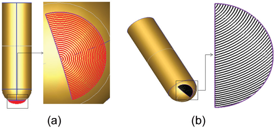
Meanwhile, for five-axis machining, cutter orientation or posture is probably the most important process parameter. 15 A cutter posture is usually described by its lead and tilt angles, defined against the cross-feed and feed directions during machining (see Figure 1(a)). Intuitively, the introduction of cutter posture as an extra variable would make chatter prediction more complicated. An example is provided in Figure 2, showing a ball-nose cuter machining, a straight ‘ditch’ on a flat surface with different cutter postures. The machining parameters are kept exactly the same in both cases (depth of cut: 0.5 mm, spindle speed: 4800 r/min, material: AL5075) except the cutter posture. As shown in Figure 2, completely different surface finish qualities can be observed from the microscopic images of the experiments, machined with two cutter postures that have only 20° difference in the lead angle. A clear distinction can be made between stable and chatter machining. To address the influence of cutter postures on machining stability, we propose the concept of posture stability graph (PSG), which will partition the allowable range of cutter postures into stable and unstable zones. The target is to use the knowledge of machining dynamics to guide the selection of cutter postures during process planning in an integrated manner.
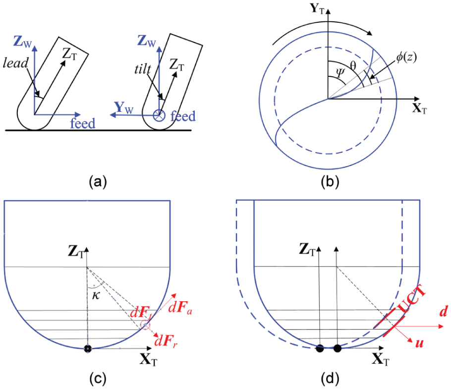
Cutting force prediction in five-axis machining: (a) CCS, (b) top view of CCS, (c) discretization of cutter geometry, and (d) calculation of UCT.
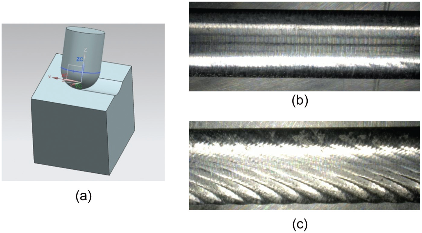
Influence of cutter posture on chatter stability and surface finish quality: (a) slotting with a ball-nose cutter, (b) lead angle: 60°; tilt angle: 0°, and (c) lead angle: 40°; tilt angle: 0°.
Construction of PSG starts with the prediction of machining chatter in five-axis machining. Over the years, much research5,10,16–19 has been done to predict chatter in three-axis machining, most of which focuses on determining maximum chatter-free depth of cut for a specified spindle speed by modelling the machining system dynamically. Sridhar et al. 10 modelled the milling operations using linear differential difference equations with periodic coefficients, the stability of which can be identified analytically. Later, Minis et al. 16 solved the stability problem for two-dimensional (2D) dynamic milling problems with an iterative method, using Nyquist stability criterion to identify the stability limits. Budak and Altintas 5 determined the chatter stability limit analytically by approximating the time-varying directional machining coefficients using their Fourier series components. Many other methods stem from this approach, aimed at better accuracy and lower computational cost. A more detailed discussion on them is provided in section ‘Stability analysis with FD method’ later in this article when we explain the reason behind our choice of method.
In the meantime, limited study is reported for chatter stability of five-axis milling. Generally speaking, the introduction of different cutter orientations other than the one normal to the machining surface affects chatter stability in two ways: (1) it changes the cutter–workpiece engagement condition, which effectively determines the dynamic machining force. (2) It affects the distribution of modal parameters regarding the feed direction, that is, the two orthogonal degrees-of-freedom (DOF) of the cutter will no longer be aligned with the feed and cross-feed directions as in three-axis machining. Some of the early works to identify these influences are those of Ozturk et al.,20,21 in which the cutter–workpiece engagement region is identified analytically under given lead and tilt angles and the modal parameters are transformed into the cutter frame. Both single-frequency and multi-frequency methods have been applied to determine the stability of the chatter equation. 22 Similar work includes that of Shamoto and Akazawa, 23 who used a variation of the zeroth order method (by predicting the mean of the cutting force) for chatter prediction. These works are significant in identifying the influence of cutter orientation on machining stability. Yet, such approaches can only deal with machining with a fixed posture, which has limited applications. Mousseigne et al. 24 addressed a special machining process when a torus cutter is used in climb milling. The experiment setting makes sure that the tool–workpiece engagement as well as the cutter’s orientation remains constant. This enables the traditional SLD to be built for the case. Ahmadi and Ismail established the stability maps relating cutter location (CL) and spindle speeds for five-axis peripheral milling of ruled surfaces. With this machining set-up, the cutter will be tangent to the machining surface. Thus, a change in CL is effectively a change in cutter orientation. 25 This piece of work is a great demonstration for the influence of cutter orientation on chatter stability. Yet, simplification by assuming the cutter–workpiece engagement condition remains constant makes it not directly applicable to five-axis end milling.
During five-axis machining of freeform surfaces, the cutter postures would be continuously adjusted. The depth of cut, as affected by residue material from previous pass, is also changing continuously between CLs. Following the approach of existing work, the only viable solution is to construct the SLD and adjust the spindle speed at each CL. However, there would be many adverse effects, such as cutter marks from the spindle speed adjustment, increased power consumption, and deviation from optimal cutter speed. A better option is to make sure that all the cutter postures are stable during process planning. This requires the partitioning of the posture solution space into chatter/stable zones, which is the idea behind PSG. An analogy can be made between the proposed method and the division of posture solution space into accessible/inaccessible regions based on interference avoidance requirements. 26
In the remaining of this article, the model of the five-axis machining system is to be presented and the method to solve for the stability of the system using the full-discretization (FD) method is to be introduced. Based on the result of the stability analysis, PSG can be constructed for any combination of depth of cut and spindle speed. Several experiments, including simultaneous five-axis machining, have been designed and conducted to validate the proposed method.
Chatter prediction for five-axis machining
Chatter is predicted based on the stability of the machining system under the excitation of cyclic machining forces. In this section, the dynamic model of the machining system is to be established, followed by the introduction of the proposed method to determine the stability conditions of any given cutter posture.
Cutting force model in five-axis machining
Chatter prediction starts with the prediction of cutting force, which acts as the excitation input for the machining system. Cutting force prediction is conducted under the assumption that only ball-part of the cutter is engaged with the workpiece, which is generally true for five-axis machining as it is mainly intended for finish machining purposes.
For five-axis machining, the cutter’s orientation is described with a pair of lead and tilt angles with respect to the feed direction of machining. For convenience, a workpiece coordinate system (WCS)
where c(tilt) is short for cos(tilt), and s(tilt) is short for sin(tilt), and this abbreviation will be used in the remaining of this article.
Cutting force prediction is conducted in CCS. As cutting edges are helical on ball-nose cutters, the cutter is discretized along the cutter axis into N layers.
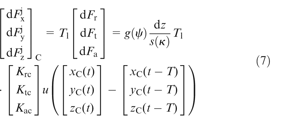
A cutting edge segment on a layer can be assumed straight and undergoing oblique cutting conditions. 27 The cutting force generated by a single elemental cutting edge is decomposed into tangential, radial, and axial cutting forces, denoted as dFt, dFr, and dFa, respectively, and given as 1

where Kte, Kre, and Kae are the edge force coefficients and Ktc, Krc, and Kac are the shear coefficients, which can be calibrated for any given combination of cutter and material. dS is the differential element length of the cutting edge, db is the uncut chip width, and t is the uncut chip thickness (UCT) at the elemental cutting edge. From a kinematic point of view, tuct can be calculated as the displacement of the cutter projected along the surface normal at location of the elemental cutting edge given as
where κ and ψ are the height and angular position angles of the cutter element, respectively, (see Figure 1(b) and (c)), [x(t) y(t) z(t)]T gives the location of the cutter centre at time t, and T is the tooth passing period of the cutter.
During machining, a cutting edge will enter and exit from the engagement region. When mapped onto each cutter disc, the engagement region is represented with one or several pairs of entry and exit angles (φst, φex). Cutting force will only be generated by certain cutting edge elements whose angular positional angle satisfies φst < ψ < φex. Hence, the following step function g(ψ) is proposed
Finally, the elemental cutting force can be transformed to the cutter frame as
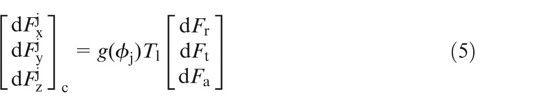
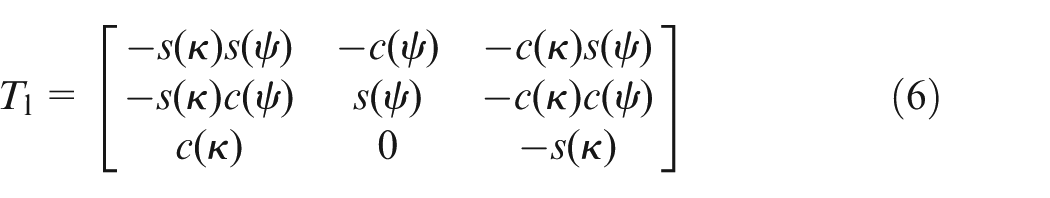
where Tl is the transformation matrix given as
A summation of the elemental cutting forces contributed by each cutter disc will give the total cutting force acting on the cutter. The engagement region can be obtained via geometric analysis. It is worth noting that when machining with a ball-nose cutter, the change in cutter postures will not affect the shape of the engagement region, but only the distribution of the region on the cutter surface. This means engagement information for any posture can be reconstructed from that of a single input posture with reduced computation load (see Figure 3). 28
Construction of engagement information for prediction of cutting force: (a) engagement information of three-axis posture and (b) engagement information of five-axis posture reconstructed from three-axis posture.
Dynamic model of machining system
In our model, the cutter is assumed to have two DOF in two orthogonal directions, both normal to the cutter axis. The modal parameters along these two directions can be obtained with two separate impact tests. A modal frame
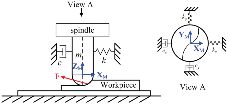
Illustration of dynamic machining system.
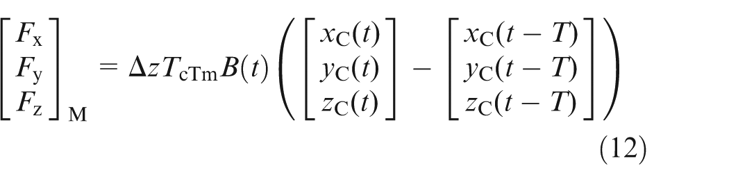
During machining, the static part of the machining force, that is, the part proportional to dS, which is not affected by the UCT, will not contribute to the regenerative mechanism (the cause behind chatter) and will thus be dropped. Substituting db = dz/s(κ), where dz is the thickness of one cutter disc, the following equation can be obtained
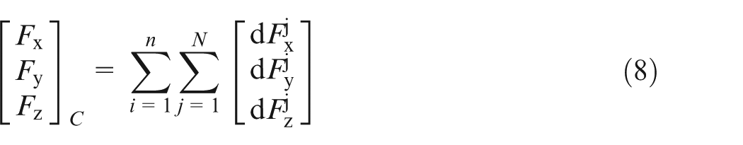
The additional subscript in xC(t) indicates that the calculation takes place in CCS. Summing up the elemental cutting force from all the involved edges, the total dynamic forces are calculated as
Defining
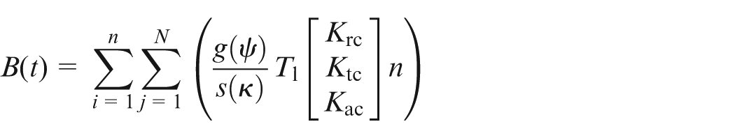
Equation (8) can be rewritten as
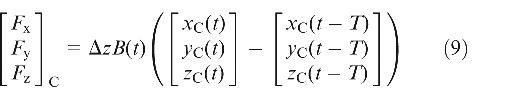
So far, the cutter displacements and corresponding cutting forces are all calculated in the CCS. However, it should be noted that it is impossible in practice to align the modal frame with every CCS corresponding to each cutter posture when impact test is done on the machine. For the sake of convenience, the impacting directions are selected to be along the machine’s X and Y directions when every rotary axis is at zero position on the machine (see Figure 5). The modal frame will also rotate with the cutter when a certain posture is taken by the cutter. The transformation matrix between CCS and the modal frame will therefore be determined by the machine’s structure.
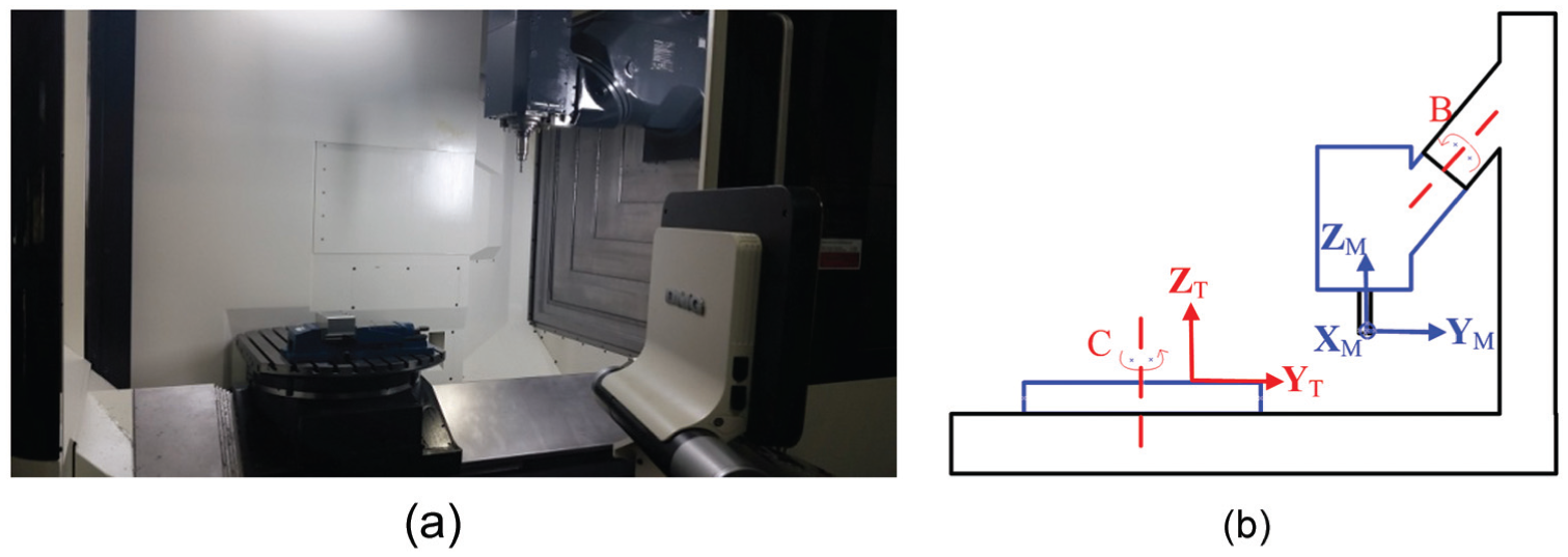
Determination of impact testing directions: (a) five-axis machining centre and (b) illustration of machine structure.
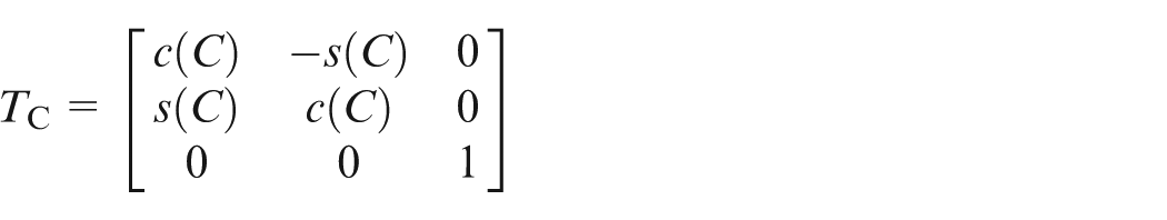
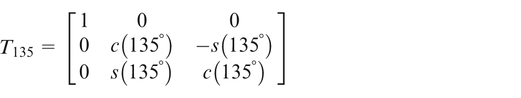
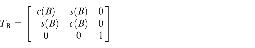
For instance, in our experiments, the used machine (model: DMG 80P duo Block) has a non-orthogonal swivel head configuration. The transformation between the modal frame and the workpiece frame is given as

where TtTw is the transformation matrix from the machine table to the workpiece, determined by the way the workpiece is set up on the table and the other matrices are given as
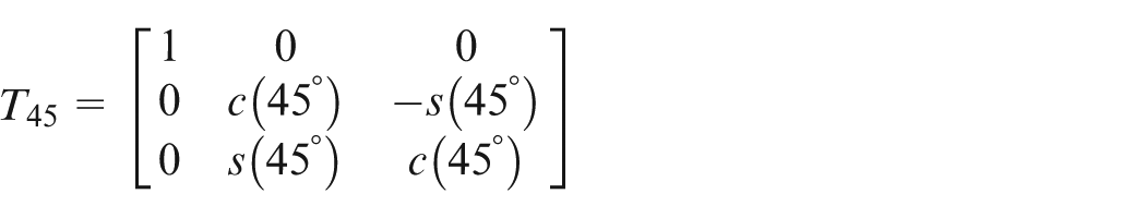
Following this, the transformation matrix between the cutter and modal coordinate systems can be obtained as

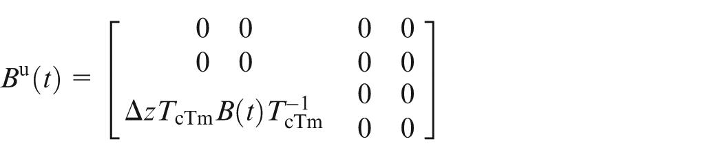
Multiplying TcTm on both sides of equation (9) gives us
The dynamic equation for our model of machining system can be written as
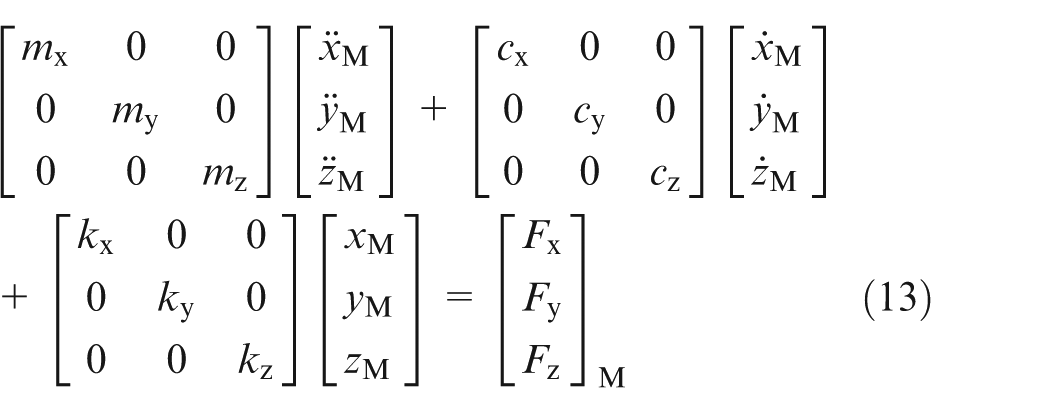
which can be rewritten as
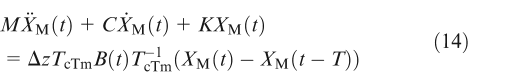
where M, C, and K represent inertial, damping ratio, and stiffness matrices of the system, respectively, obtained through impact testing. XM is a column vector representing the displacement of the cutter in the modal frame. Equation (14) is the general expression for five-axis machining. In reality, as the stiffness in the Z direction is very high, the terms in Z direction are usually dropped.
Stability analysis with FD method
It is obvious that equation (14) is a delay differential equation (DDE). At a specified spindle speed, which corresponds to a specific value of the tooth passing period T in equation (14), the stability of the equation determines whether chatter exists during machining. Over the years, many attempts have been made by researchers to solve for stability condition. The time domain simulation is proposed by Smith and Tlusty. 29 Although it is the most accurate method to calculate the critical value, it is highly time-consuming. Altintas and Budak 30 presented the zeroth order approximation (ZOA) method using the zeroth order Fourier term to approximate the time-varying cutting force coefficients in milling. However, this method cannot accurately predict the critical parameters at low radial immersion milling operations. 31 Subsequently, the multi-frequency method was proposed to deal with this problem by extending the ZOA method. 32 However, the order of the Fourier term is still difficult to choose. Semi-discretization (SD) method was proposed to convert the DDE into a series of autonomous ordinary differential equations (ODEs), and then the stability of the system is determined by calculating the eigenvalues of the transition matrix, constructed using the coefficients of the series ODEs.31,33 Temporal finite element analysis (TFEA) was proposed to deal with highly interrupted milling process. 34 However, this method is only suitable for very low radial immersion milling process. Ding et al. 35 presented a FD method which is similar to the SD method in the sense that both methods approximate the original DDE by a series of ODEs but produces better computational efficiency. In this article, the FD method is used to determine the stability in five-axis milling in our work.
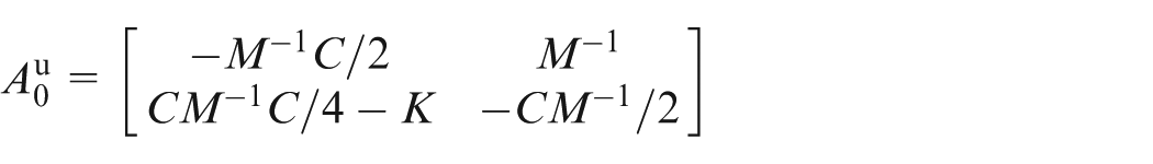
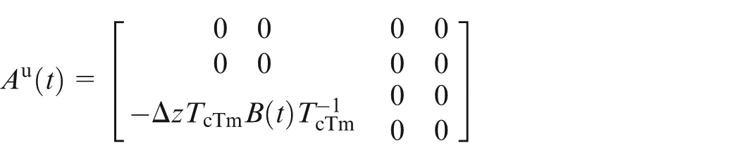
First, the state variable U is defined as
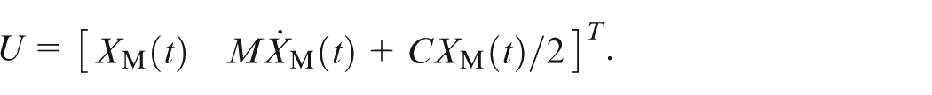
With the state variables U, equation (14) can be rewritten as

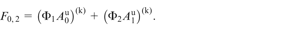
where
The main idea of FD method is to discrete the time period T into m small time interval such that T = µτ. Based on the direct integration scheme, on arbitrary time interval kτ ≤ t ≤ (k+1)τ, with the initial condition uk = u(kτ), the response of equation (15) can be obtained via the direct integration scheme as
Equivalently, it can be expressed as
where 0 ≤ t ≤ τ. Then, uk+1, then u(kτ+τ) can be obtained using
Equation (18) can be rewritten as
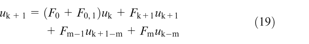
where
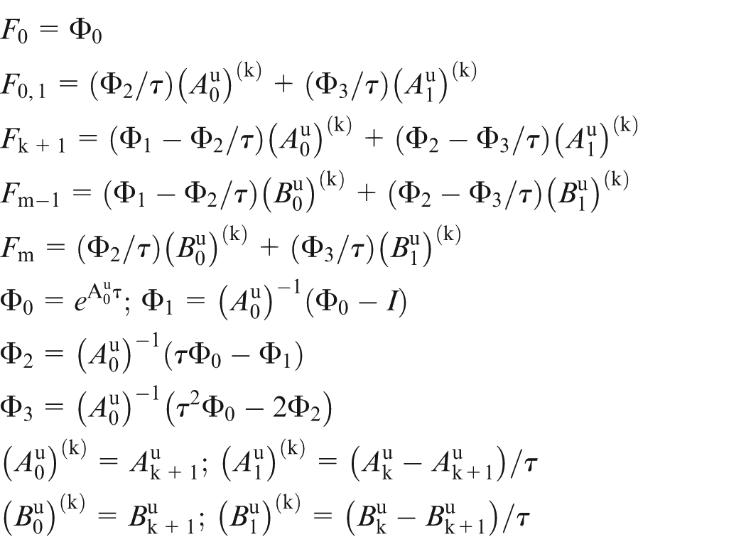
If the matrix [I−Fk+1] is non-singular, uk+1 can be expressed in the following explicit form
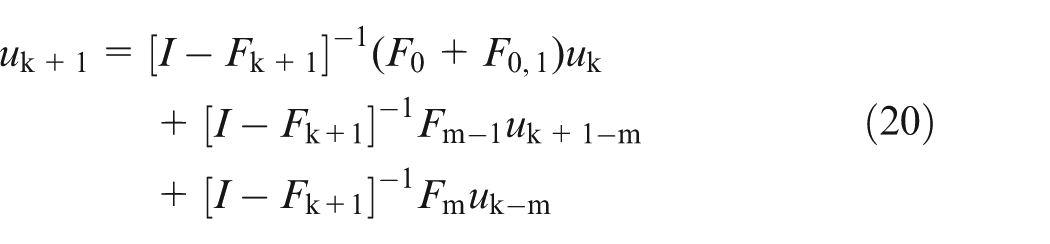
In the case [I−Fk+1] is singular, uk+1 can be obtained using

where
A discrete map can be defined as

where the vector yk denotes

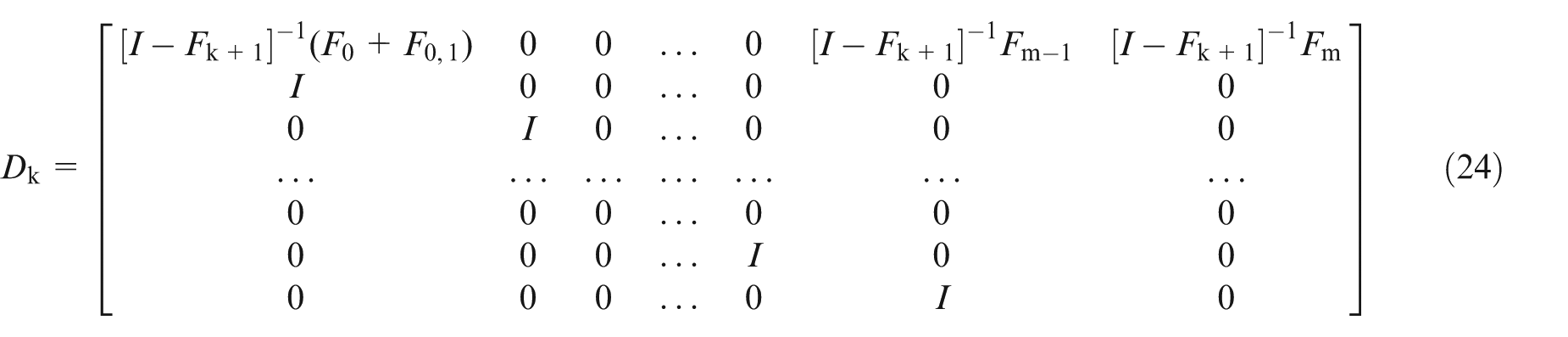
Dk is defined as
Now, the transition matrix Φ over one periodic time interval can be constructed using the sequence of discrete maps Dk, (k = 0, …, m−1), that is

where Φ is defined by

According to the Floquet theory, the stability of the system can be determined in the following way: if the modulus of all the eigenvalues λΦ of the transition matrix Φ is less than 1, the system is stable, otherwise, it is unstable.
Construction and application of PSGs
With the proposed methods, given a combination of spindle speed, depth of cut, and cutter posture, whether machining will be stable can be determined. Spindle speed will be fixed by recommended cutting speed, which leaves two important parameters during tool-path generation, that is, depth of cut and cutter orientation. For any depth of cut, the feasible range for cutter orientations can be divided into stable and unstable regions. Postures should only come from stable regions, which is the idea behind PSG.
Generation of PSG at a certain depth of cut relies on a sampling algorithm. The boundary between stable and unstable machining will be the set of cutter orientations for which the ∣λΦ∣ of the transition matrix Φ are equal to 1. For cutter postures with ∣λΦ∣ larger than 1, the postures will be unstable and for those with ∣λΦ∣ smaller than 1, the postures will be stable. 35
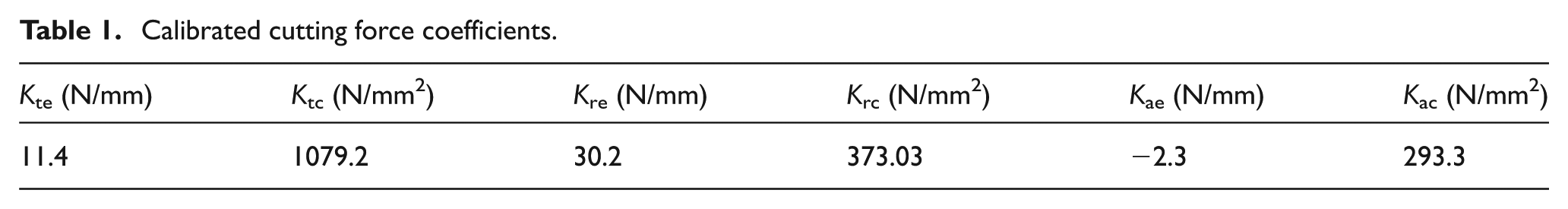
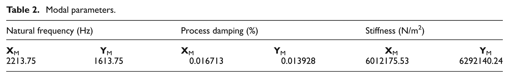
The chattering behaviour of a certain machining process is heavily affected by the engagement area between the cutter and the workpiece. In this article, experiments are carried out at the simple scenario of slotting on a plane (see Figure 2(a)). The engagement information for such a scenario is easy to obtain. The tool of PSG construction could be applied to freeform machining scenarios as well, as long as the cutter–workpiece engagement condition is provided. The machine tool used is a DMG 80P Duo Block five-axis machining centre (see Figure 6). The material to be machined is AL7075 and cutter is a Mitsubishi carbide cutter with 10 mm diameter. Spindle speed is set at 4800 r/min. The cutting force coefficients and modal parameters are provided in Tables 1 and 2, respectively.
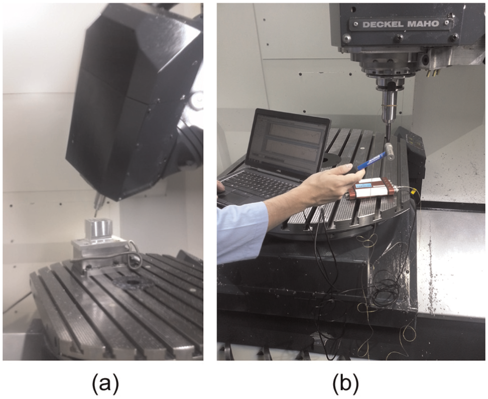
Setup of cutting experiments and impact test: (a) for cutting experiments and (b) for impact test.
Calibrated cutting force coefficients.
Modal parameters.
Following the sampling algorithm, PSG is first generated for a cutting depth of 0.5 mm as shown in Figure 7(a). The sampling is conducted at 1° for both lead and tilt angles. The range of sampling for both lead and tilt angles are set as 60°, large enough to cover the range of practical machining. The horizontal and vertical axes of in Figure 7 represent the tilt and lead angles, the combination of which determines a cutter posture. Thus, the rectangular area defined by these two axes gives the allowable range for cutter postures. The contours on the graph give the postures that share the same value of ∣λΦ∣. The contour with ∣λΦ∣ = 1, as explained before, is the boundary between stable and chatter machining, whereas contours with value of ∣λΦ∣ smaller or larger than 1 correspond to stable and chatter postures, respectively. The PSGs are also generated for the cutting depth of 0.6 and 1 mm as well, as shown in Figure 7(b) and (c). It can be seen clearly that the unstable region has enlarged in accordance with our expectations. In Figure 8, the PSGs at these three different depths of cut are summarized into a complete PSG. Each contour represents the stability boundary at the depth of cut indicated by the number on it, taken as the line with ∣λΦ∣ = 1 from the corresponding PSG. The benefit of such a summarized PSG is two-fold: first, it demonstrates clearly how the stable region enlarges with the reduction in depth of cut; second, for depth of cut other than the three indicated values, the stability region of the next larger depth of cut can be chosen as a conservative measure. The complete work flow for construction of PSGs is illustrated in Figure 9.
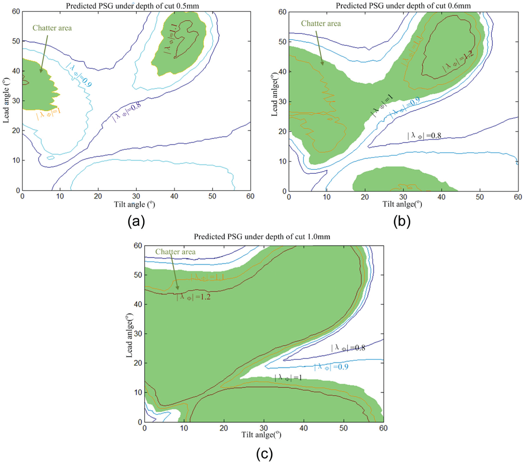
PSGs for slotting on a flat surface at spindle speed 4800 r/min: (a) depth of cut = 0.5 mm, (b) depth of cut = 0.6 mm, and (c) depth of cut = 1.0 mm.
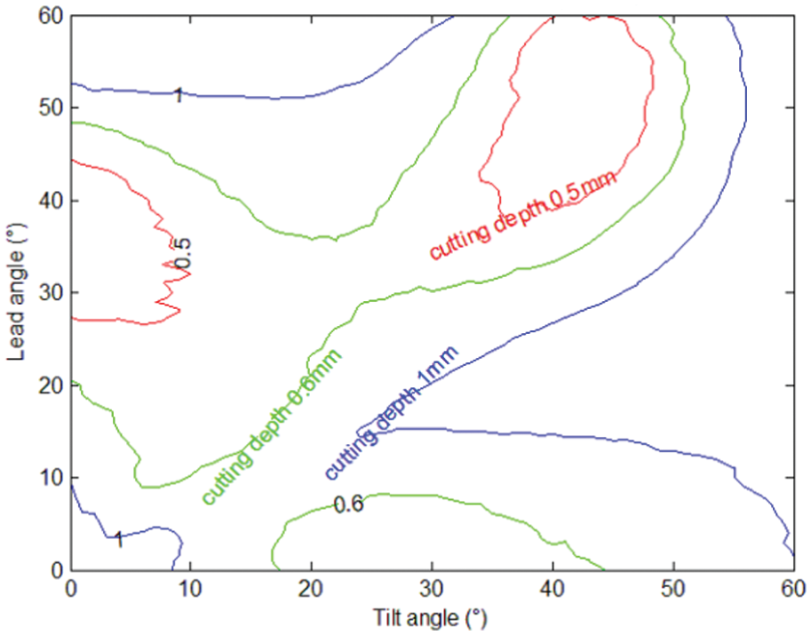
Summarized PSG corresponding to Figure 7(a)–(c).
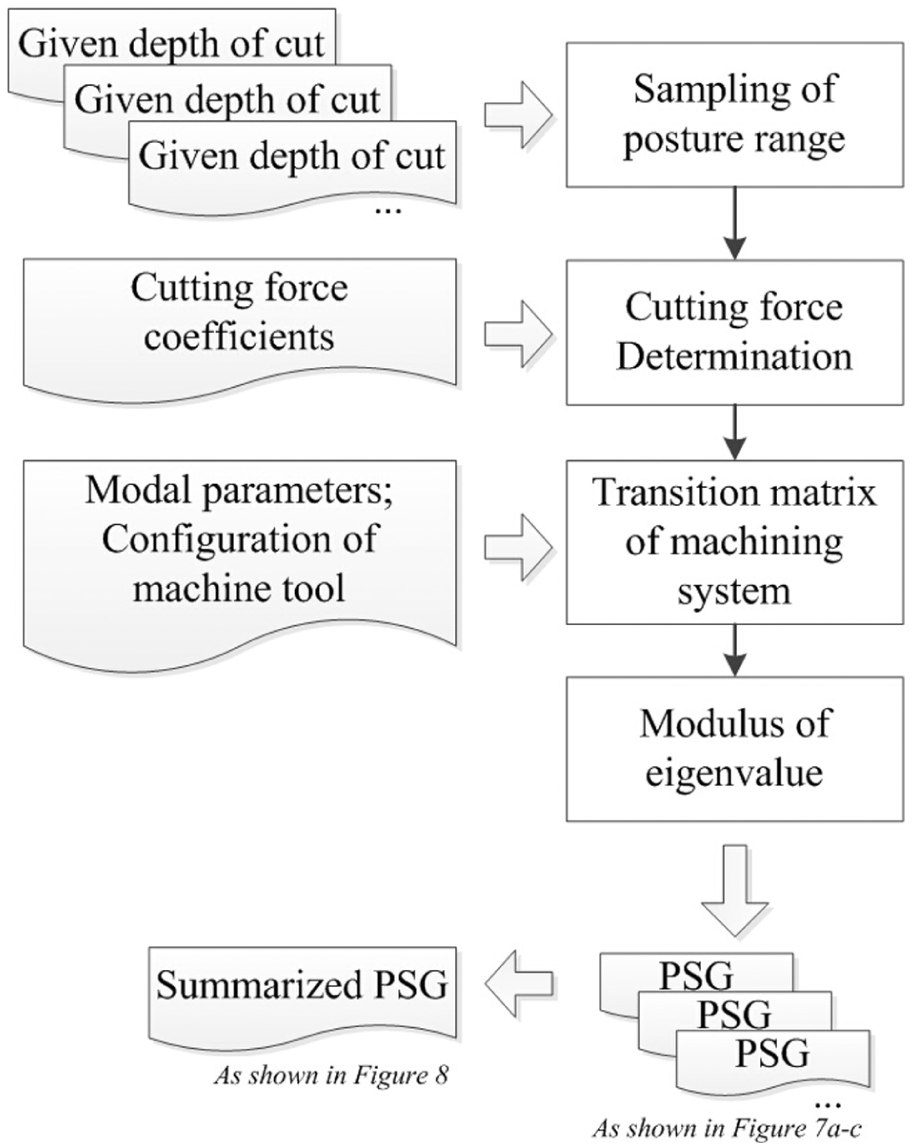
Flowchart for PSG generation.
To test the validity of generated PSGs, a series of machining experiments have been carried out under indexed machining mode, with which the cutter’s posture is pre-set and will remain the same during one pass of machining, leaving a consistent machined surface. The first set of the experiments was carried out with a depth of cut at 0.5 mm. The results are shown in Figure 10, where the cutter postures experimented with have been overlaid over the PSG. It is obvious that this is the same PSG as shown in Figure 7(a) but showing only the boundary of the chatter zone, that is, the contour with ∣λΦ∣ = 1. Microscopic images for some of the finished machining surfaces are also provided in Figure 10. It can be seen that a high level of conformity has been achieved between our prediction and the experimental results.
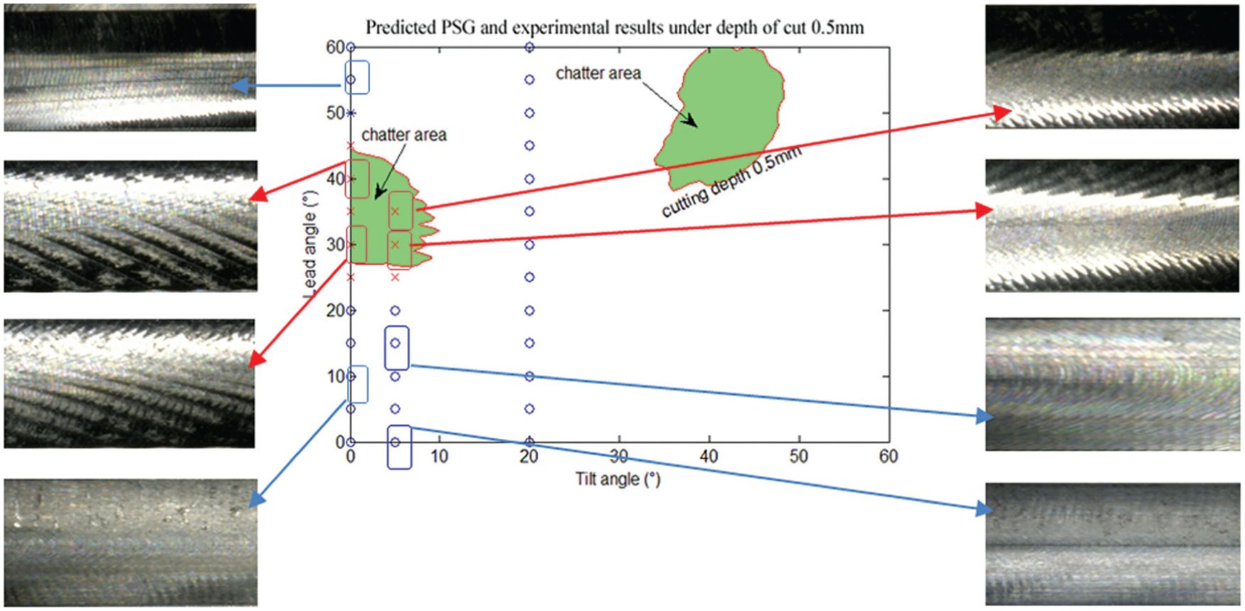
Stability comparisons between predicted and experimental measurements.
Another experiment is carried out under the simultaneous machining mode as shown in Figure 11 when the cutter posture is continuously adjusted from (L: 0°, T: 0°) to (L: 60°, T: 0°) smoothly with a depth of cut 0.5 mm over 21 CLs with an interval of 5 mm. The interpolation from the starting to the ending cutter posture is conducted by commercial CAM software (Unigraphics NX 8.5). At the intermediate CLs, the lead and tilt angles have been retrieved as given in Figure 11.
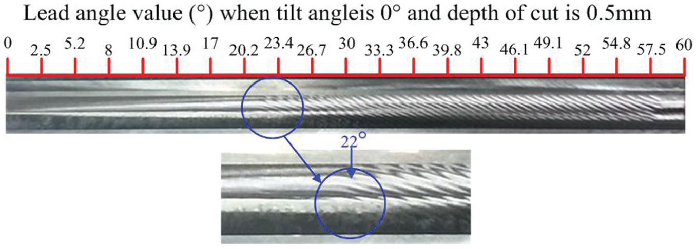
Machined surface under varying cutter posture with depth of cut 0.5 mm.
According to the PSG, the machining will enter chatter zone after the 10th CL (corresponding posture: L: 26.7°, T: 0°). This is generally in accordance with the microscopic image of the machined surface, in which chatter emerges at around 22° as shown in Figure 11, which demonstrates the effectiveness of our algorithm. In addition, according to the PSG, the machining will enter stable area after the 19th CL (corresponding posture: L: 54.8°, T: 0°). This is also in accordance with the microscopic image of the machined surface, in which chatter disappear at around 58° as shown in Figure 11. The minor difference between the predicted key posture and experimental key posture may be caused by the measurement deviation for modal parameters and ignored influence of cutting force along the cutter spindle.
Conclusion
In this article, PSG is proposed to guide the determination of chatter-free cutter postures during five-axis machining. A procedure to obtain the PSG has also been established. At first, a dynamic model of the machining system under cyclic cutting force is established, in which the influences of the cutter posture, depth of cut, and spindle speed have all been accounted for. The stability of the machining process is then derived from the transition matrix of the system. By identifying cutter postures that will lead to borderline stability under a certain machining condition, the feasible range of cutter orientations will be divided into stable and unstable zones, which makes the PSG. Machining experiments have been conducted and the results verified the validity of PSG under both indexed machining and the simultaneous machining. The development of PSG is meaningful for the integration of process planning and machining dynamics. Our future work will focus on applying our algorithm for freeform surface machining with varying cutter–workpiece engagement conditions.
Footnotes
Appendix 1
Declaration of conflicting interests
The author(s) declared no potential conflicts of interest with respect to the research, authorship, and/or publication of this article.
Funding
The author(s) received no financial support for the research, authorship, and/or publication of this article.