
Abstract
Because of notable distortion in high-speed milling of grid sheet, it is difficult to choose a feasible processing scheme for this kind of workpiece. This article attempts to present a method to analyze the stress and deformation of grid sheet under different processing schemes based on a coupled mechanical–thermal finite element model, which provides a convenient and flexible platform to evaluate the performance of processing scheme in high-speed milling and optimize the cutting conditions. After a thorough analysis of the whole milling process of grid sheet, the tool path was discretized to make it convenient for the modeling of material removal process. An analytical thermal load calculation method and an experimental mechanical load calculation method were adopted to determine the loads exerted on the grid sheet. The constraint of the fixture was also considered, and finally, an ANSYS Parametric Design Language–based finite element method model was established. Based on this model, stresses and deformations under a given processing scheme with or without considering heat effect were compared, and it shows that cutting heat has great effect on the magnitude and distribution of deformation and stress. In addition, effects of some parameters on machining quality were investigated, and it was found that radial depth of cut has more impact than other parameters.
Introduction
Grid sheet, a thin-wall, aluminum alloy workpiece used in rocket fuel storage tank, was previously processed by chemical milling which has the shortcomings of uneven thickness of wall, redundant weight and inefficiency. 1 Compared with chemical milling, high-speed milling has the advantages of high efficiency and machining quality. Due to variations of sheet’s dimension, materials, type of grid and so on, the processing scheme for each kind of grid sheet is unique, and no existing technology or cutting database could be taken for reference. Under the joint action of cutting force, clamp force and cutting heat, unreasonably selected high-speed machining parameters usually induce notable stress and deformation of grid sheet. Therefore, judging the validity of a given processing scheme is an essential prerequisite for grid sheet machining.
There were mainly two ways to investigate the performance of a processing scheme. The first one is experimental method. For example, through design of experiments (DOEs) on milling process, Alberti et al. 2 investigated the influence of feed rate, interpolation and type of holder on dimension error and cycle time. Similarly, Vivancos et al. 3 inspected the impact of high-speed cutting parameters, such as cutting speed, feed per tooth, axial depth of cut and so on, on the roughness of workpiece. Bissey-Breton et al., 4 Sun and White 5 and Coelho et al. 6 inspected the effect of tool geometrical parameters on machining quality by experiment. In the same way, there were also some researches on the effect of tool path7,8 and coolant on the cycle time and surface quality. 9
The second one is numerical method. For instance, Zaghbani and Songmene 10 calculated the cutting force and temperature of aluminum alloy under dry high-speed milling condition using analytical model and numerical simulation. Wang et al. 11 predicted cutting forces in three directions and chip morphologies in end milling of Ti-6Al-4V using ABAQUS/Explicit. Ulutan et al. 12 applied three-dimensional finite difference-based model to predict temperature in machining of AISI 1050. Huang et al. 13 also predicted the cutting force, temperature and residual stress of 40CrNiMoA based on ABAQUS. Despite these studies which mainly focused on the tool–workpiece cutting mechanism, that is, cutting force, tool stress and temperature rise due to the cutting heat, there were only a few researches investigating the influence of high-speed milling scheme on machining quality of thin-wall workpiece by numerical simulation, and the models developed did not take into account the effect of most of the factors, such as machining parameters, fixture layout, tool path strategy and so on.
Comparing with experimental method, which is incapable of investigating all factors’ effects on machining quality and is also difficult to obtain all the information such as stresses and deformations, numerical method, especially the finite element method (FEM), is not only able to simulate various structure and various load but also able to simulate different machining parameters, fixture layout and tool path plan during the milling process. In addition, finite element analysis (FEA) is powerful enough to provide nearly all the information about the process, such as cutting temperature, forces, stress, strain and so on. Therefore, increased attention has been paid to the development of a computationally efficient milling process model, which is well suitable for the simulation of low-rigidity structural workpiece machining and prediction of the machining quality under different processing schemes.
In this work, a thermal–mechanical coupled FEM model was developed to simulate the machining process of grid sheet in high-speed milling and evaluate the performance of processing schemes with different parameters such as spindle speed, feed per tooth and radial depth of cut.
Characteristics of grid sheet’s high-speed milling process and influential factors
Characteristics of grid sheet’s high-speed milling process
Several kinds of processed grid sheet with different shapes of grid are shown in Figure 1. It can be seen that a finished workpiece consists of massive ribs and grids that were carved out from a whole sheet. When the grid sheet is being machined with a high-speed and high-feed rate cutting tool, redundant material is gradually squeezed, sheared and removed from the thin-wall sheet. During this process, under joint action of cutting force, clamping force and cutting heat, grid sheet is liable to notable distortion and stress, so it is difficult to guarantee the machining quality. Because of the complex interaction between thermal field and mechanical field, high-speed milling is a highly nonlinear, thermal–mechanical coupled process, which makes it impossible to model it analytically or obtain all the information merely from the experiments.
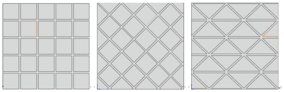
Several types of processed grid sheet.
Factors influencing machining quality of grid sheet in high-speed milling
There are numerous factors influencing grid sheet’s machining quality in high-speed milling, such as machining parameters, tool path strategy, materials of tool and workpiece, tool geometrical parameters, fixturing, initial residual stress, structure of workpiece and so on. Practically, material of workpiece and cutting tool are seldom replaced, tool path strategy, fixture layout and tool geometrical parameters such as rake angle are also fixed; therefore, the most important factor affecting the cutting process is machining parameter or processing scheme. Not only does processing scheme directly determine the cutting force and cutting heat and consequent machining quality but also determine machining efficiency. Therefore, it is necessary to evaluate a processing scheme before its going into manufacturing.
FEA procedure and system architecture
As discussed above, there are lots of factors influencing grid sheet’s machining quality, and the interaction mechanism between temperature and stress of grid sheet is so complex that it makes it impossible to utilize experimental method to obtain all the information from the milling process while taking all these influential factors into account.
Therefore, a thermal–mechanical coupled FEM method was developed to analyze the effect of processing scheme on the machining quality of grid sheet. The overall modular architecture of the developed model is shown in Figure 2. It mainly comprises four modules, that is, geometrical modeling, meshing, load applying and constraint applying module. Geometrical modeling module is used to model the process of material removal according to processing schemes and tool path plan, load applying module to simulate the thermal and mechanical load applied on the workpiece based on processing scheme and constraint applying module to model the action of fixturing. The analysis procedure could be summed up as follows (as shown in Figure 3):
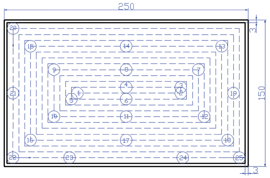
Step 1: According to the dimension of the sheet and grid, determine the positions of all grids and build the geometrical model of the whole sheet and all grids. To make it convenient for the geometrical modeling of grid sheet processing, as to a grid sheet shown in Figure 4(a), first determine the number and position of those n grids with center position
Step 2: Discretize tool path in grid i. As to a grid sheet with a given structure, the processing scheme for all grids is similar; therefore, an optional grid i was chosen to analyze the milling processing of grid sheet. The tool path for grid i is illustrated in Figure 4(b), in which the processing method is a climb cutting with a processing path of spiral inside-to-outside cutting. To reduce the computing time and workload, m key machining points with tool center positions
Step 3: Create the geometrical model of grid sheet when the tool is cutting at key machining point j. To analyze the milling process of an optional grid i on the sheet, it is unnecessary to compute the whole tool path but only these m key machining points. Assuming that the tool is currently machining at key machining point j, the removal of material from current grid and previous grids could be easily simulated by FEM geometrical modeling.
Step 4: Thermal–mechanical coupled FEA of grid sheet when the tool is cutting at key machining point j. A load transfer coupled physics analysis technique was adopted to acquire the stresses and deformations of the grid sheet when the tool is cutting at key machining point j.
Step 5: Thermal–mechanical coupled FEA of the grid i. As to the m key machining points in grid i, repeat step 4 and obtain results of milling process of a whole grid i.
Step 6: Thermal–mechanical coupled FEA of all the grids on the sheet. As to the n grids, repeat steps 4 and 5 and obtain the results of milling process of a whole grid sheet.
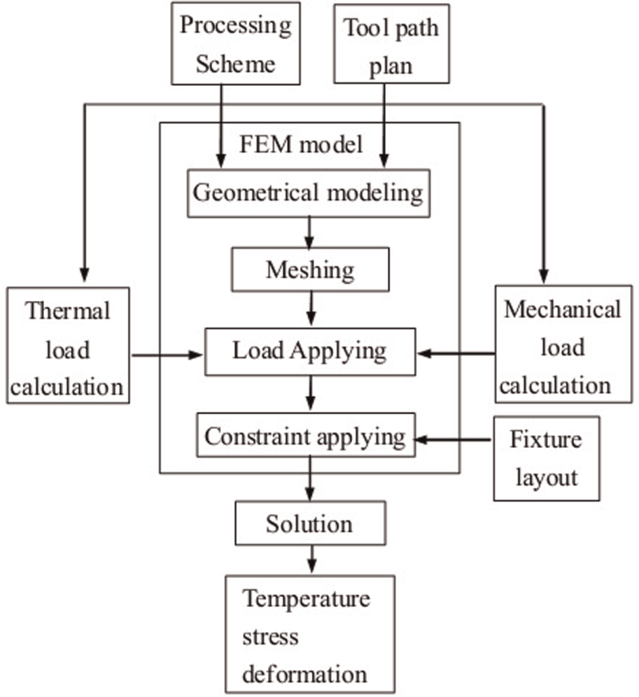
Architecture of FE model.
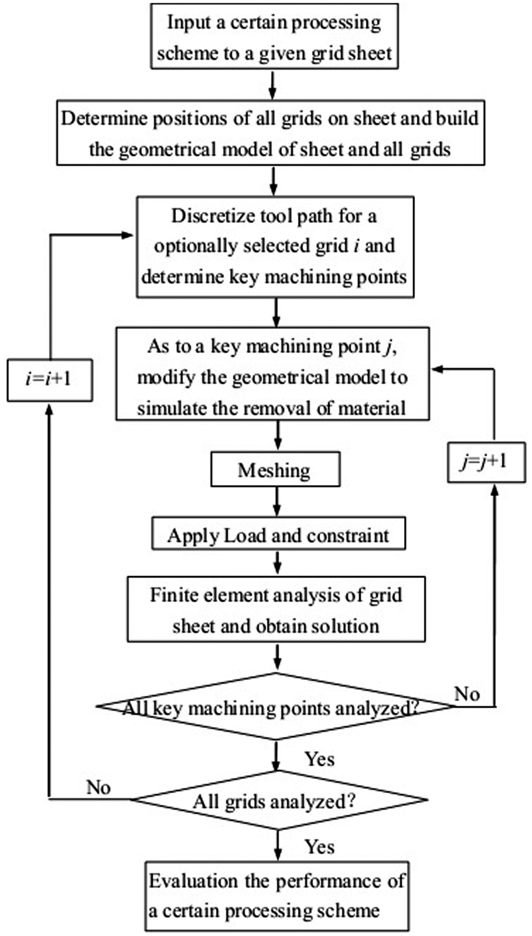
Analysis procedure of grid sheet’s behavior under each processing scheme.
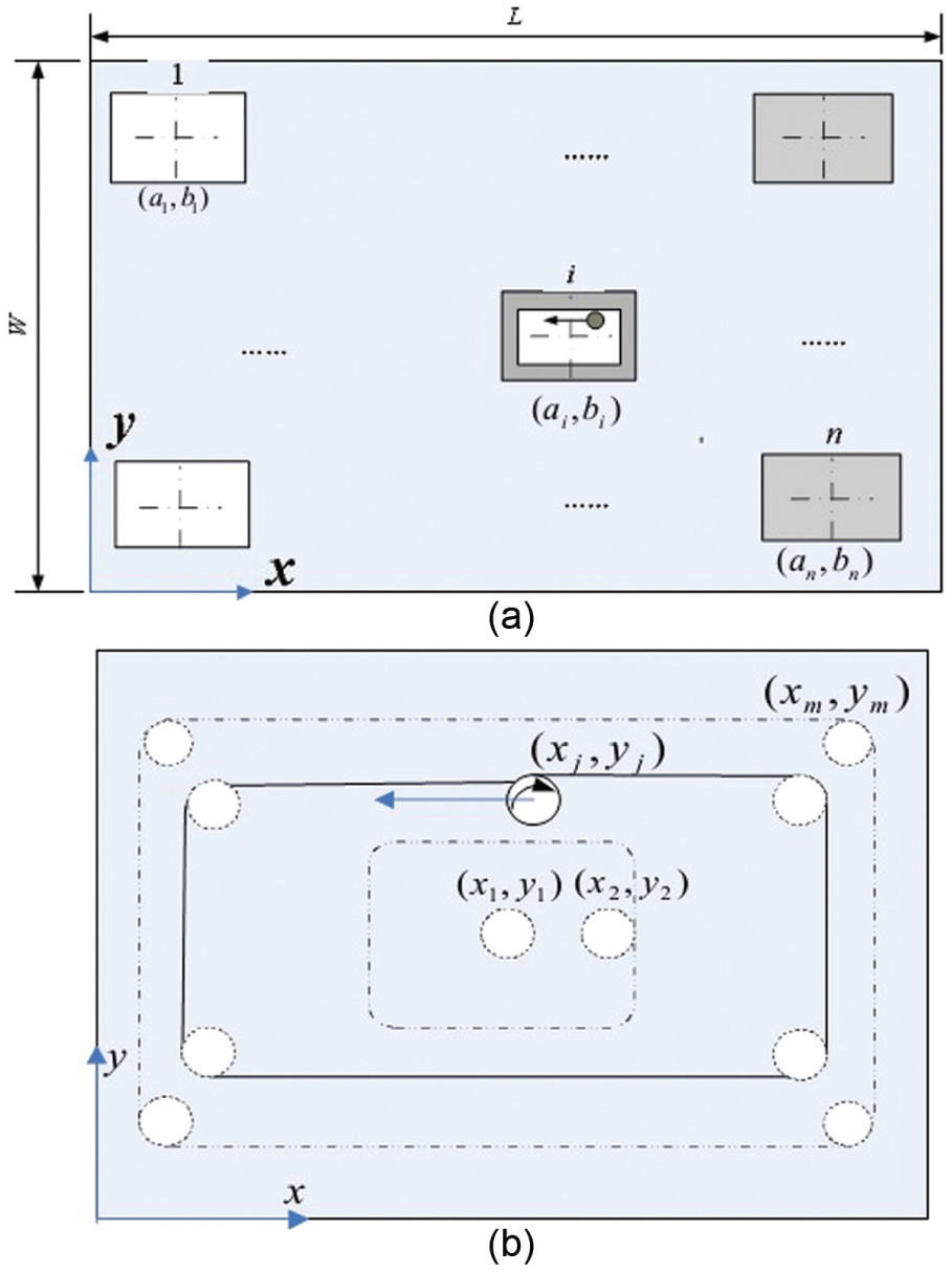
(a) Determining position of all grids on the sheet and (b) discretization of tool path in grid i.
With all the information collected from the above analysis procedure, performance of any processing scheme could be evaluated. In this procedure, finite element modeling and load applying are the two main steps, which would be detailed in the following.
Thermal–mechanical coupled finite element modeling of grid sheet
To enhance analysis efficiency and reduce repeated computing, ANSYS Parametric Design Language (APDL) tool of ANSYS was utilized to simulate material removal, load applying and solution extraction, and the FEM analysis flow is shown in Figure 5. As high-speed milling of grid sheet is a typical thermal–mechanical coupled problem discussed above, a load transfer coupled physics analysis technique was adopted to model the behavior of grid sheet. It mainly includes two successive steps, thermal analysis and structural analysis.
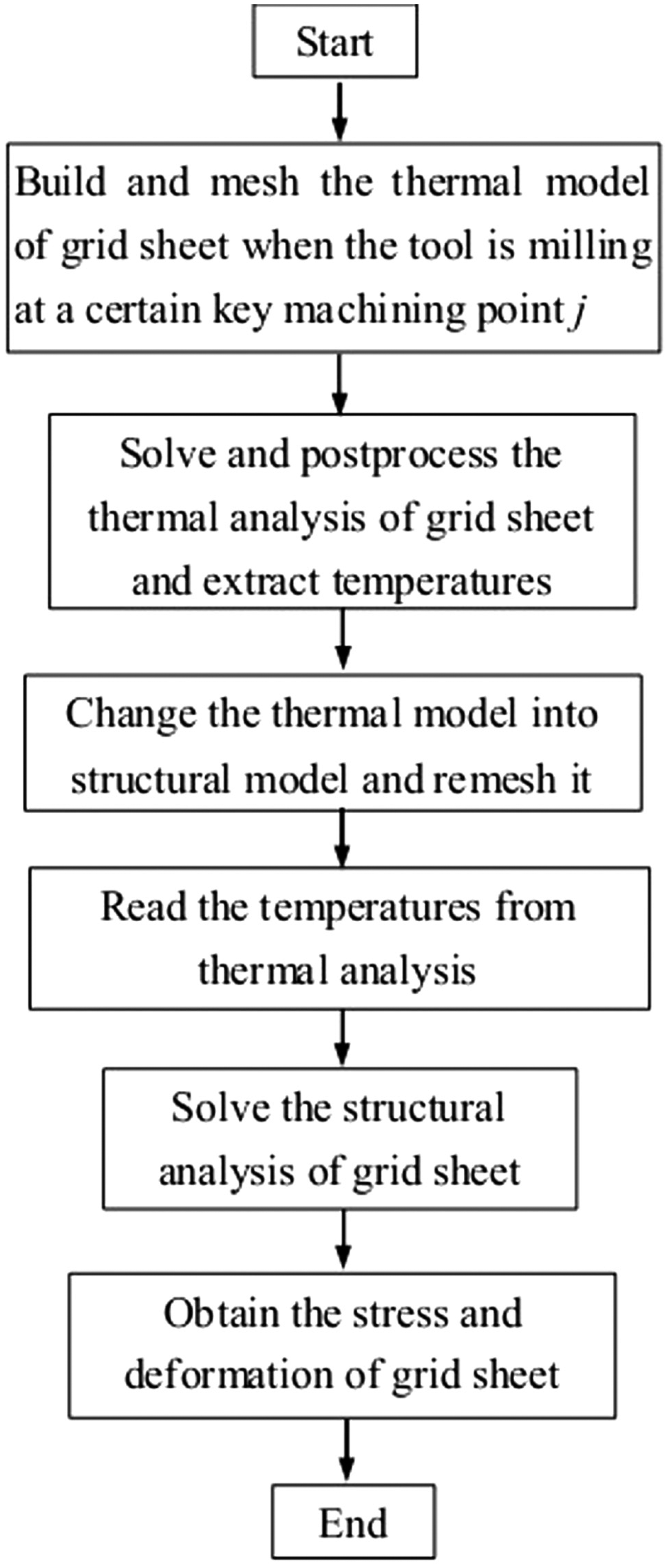
Flow of thermal–mechanical coupled finite analysis.
The following assumptions and considerations were made in the development of the FEM-based milling model:
Workpiece vibrations and cutting tool wear were excluded for simplicity.
A spiral inside-to-outside tool path strategy with dry cutting condition was considered.
The initial residual stress of grid sheet was not considered.
Temperature-independent workpiece thermal and mechanical properties were used.
Geometrical modeling and meshing
Geometrical modeling
A top-down geometrical modeling method is used to simulate the removal of material and the consequent structural change as the tool cuts through the workpiece. Other than using the death and birth feature of some selected FEM elements to simulate the effects of workpiece decreasing rigidity (due to material removal) on part elastic or plastic deformations, a direct modeling technique was utilized in this work to represent the process of material removal, that is, the entity was directly deleted by Boolean operation in ANSYS. Figure 6 shows the geometrical model of grid sheet when one grid is being machined. It could be seen that the redundant materials of processed grids and the material on the tool path before the current cutting point in the machining grid were all deleted.
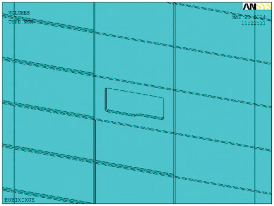
Geometrical model of grid sheet when one grid is being machined.
Meshing
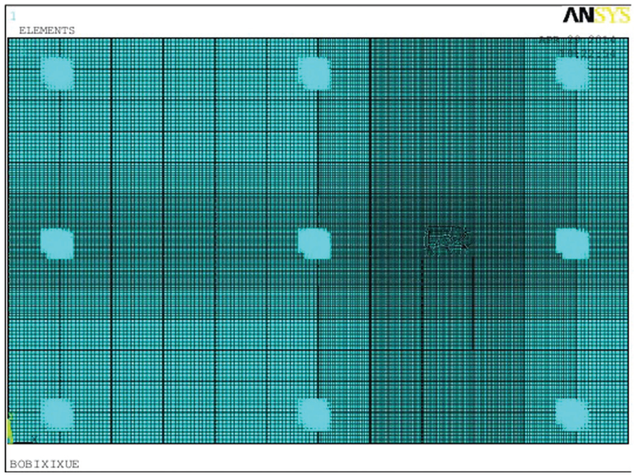
To ensure both accuracy and efficiency of analysis, a meshing method, with the following characteristic, the lesser the distance from the cutting center, the more the meshing, is put forward. To perform the sequential thermomechanical coupled field analysis, the FEM model of the workpiece was created sequentially with eight-node thermal SOLID-70 in thermal analysis and structural SOLID-185 brick elements in structural analysis. A global view and a local view of grid sheet after meshing are shown in Figure 7(a) and (b), respectively.
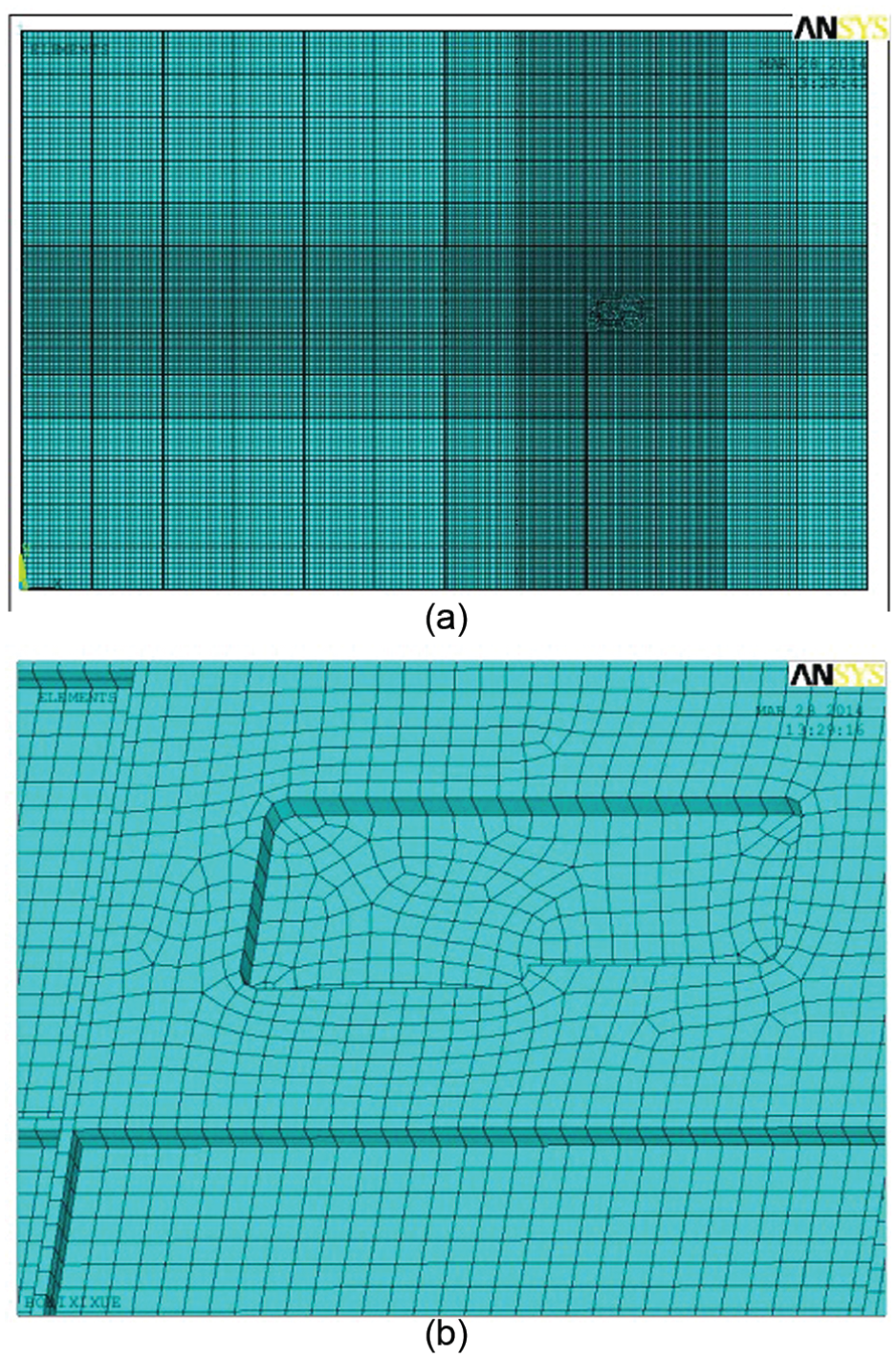
(a) A global view of grid sheet meshing and (b) a local view of grid sheet meshing.
Determination of load and boundary condition in the thermal analysis
Determination of thermal load
In high-speed milling condition, the tool moves so quick relative to workpiece that the time for the tool passing each key machining point is too short and the temperature could not change swiftly in that short time. Therefore, it could be assumed for simplicity that there is a steady heat source at the contact area between tool and workpiece, and steady-state thermal analysis is employed to analyze the temperature distribution and its impact on workpiece’s stress and deformation. In other words, end milling could be viewed as a quick moving heat source exerting on the contact surface between tool and workpiece.
During the process of high-speed milling, cutting heat is generated from three ways: 14 (1) plastic work done at the shear plane in the primary deformation zone; (2) friction at the tool–chip interface zone; (3) rubbing contact between the tool flank face and the newly machined surface of workpiece. Compared with the first two sources, the third one is very small and could be excluded. And the second one only contributes to the temperature rise of tool and chip, so it is also ignored. The only source of heat flux entering into workpiece comes from the shear deformation, and the plastic work done in the primary deformation zone could be computed as follows

where
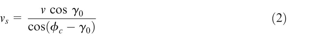
where v is the cutting speed,
And
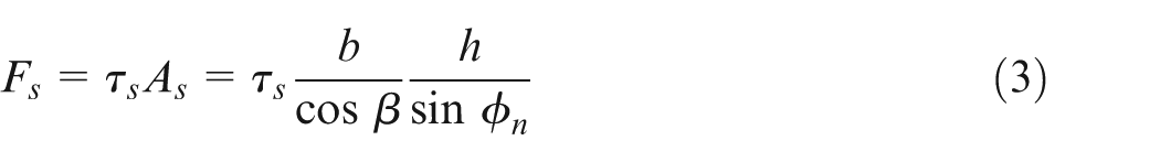
where b is the width of cut (which is axial depth of cut in end milling), h is the depth of cut (which is feed per tooth in end milling),
Provided that all works related to shear deformation changes into heat, the heat flux in the primary deformation zone is
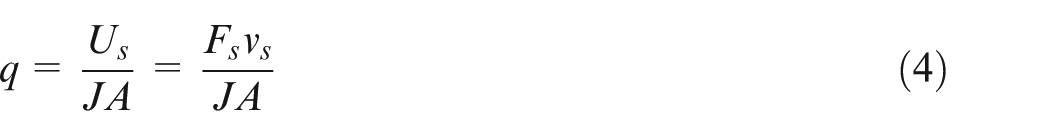
where J is the heat equivalent of work and A is the contact area between tool and workpiece. If the ratio of heat entering workpiece is
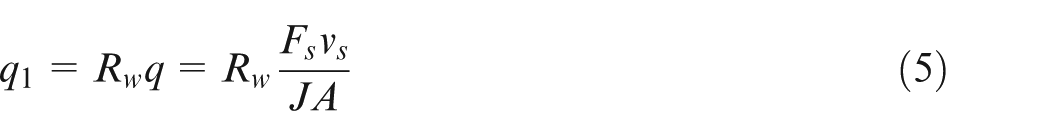
where
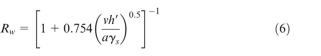
where

where
Boundary condition of thermal analysis
Since the cutting speed is relatively high, the cutting heat does not have enough time to dissipate. Therefore, the contact area between workpiece and air is assumed heat insulated as equation (9) and heat flux entering the workpiece is
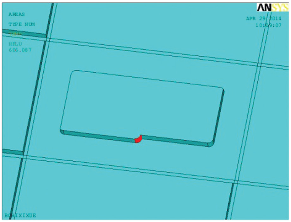
Thermal load applying on the grid sheet.
The initial temperature of workpiece is
Determination of mechanical load and boundary condition in structural analysis
Determination of mechanical load
The force applied on workpiece could be determined by the cutting force of tool, since these two forces are equal and opposite. There are two kind of cutting force models for end milling: one is analytical model 17 and the other is experimental one. 18 As to the analytical model, it is not easy to determine the cutting force because it is difficult to determine contact boundaries of the flute, and the effect of cutting parameters on cutting force is not obvious, whereas the experimental model has the advantages of fast computing, easy implementation and so on. Therefore, the experimental model 18 as equation (11) was used to predict the cutting force of tool

where
In fact, the cutting force of tool is the composition of reactions from the workpiece (as shown in Figure 9(a)), and magnitude and direction of these reactions are varied with feed direction and relative position between tool and workpiece. To apply these reactions on the workpiece, the nodes on the contact area were chosen, and cutting force in X, Y and Z directions was distributed on these nodes according to force analysis, and mechanical load applied in a given case is shown in Figure 9(b).
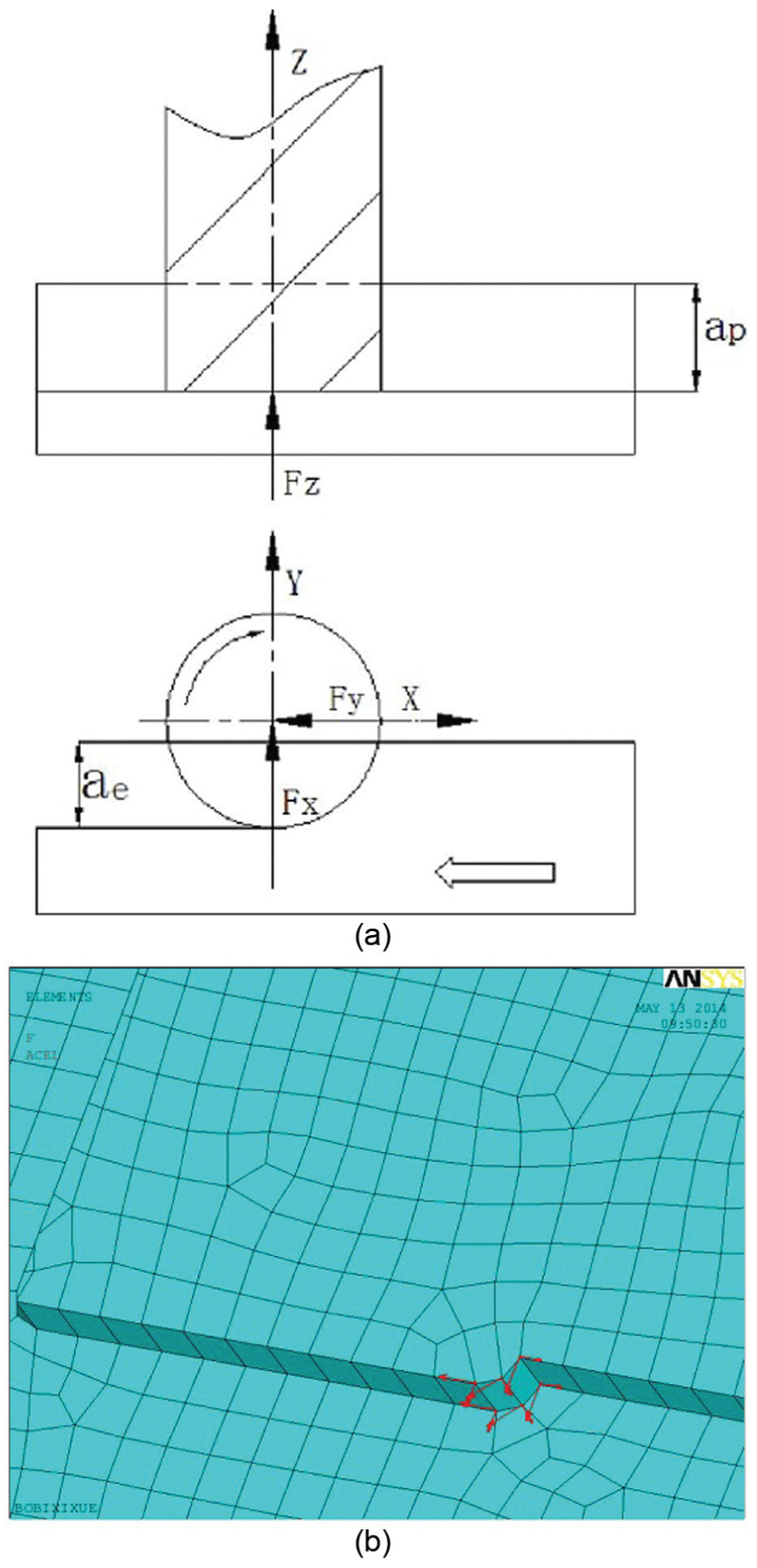
(a) Cutting force of tool and (b) cutting forces applying on the grid sheet.
Boundary condition in structural analysis
When the grid sheet is being processed, it is fixed by several vacsorb jigs, which are averagely distributed on the bottom of sheet. These jigs constrain the sheet’s displacements in X, Y and Z directions and rotation about X, Y and Z directions. Simplified constraints applying on grid sheet are shown in Figure 10.
Constraint applying on the grid sheet.
Case study
FEA of grid sheet under a same processing scheme with or without considering cutting heat
In this work, a grid sheet with an overall dimension of
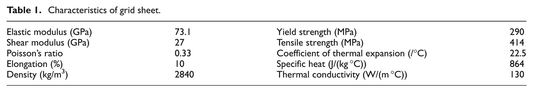
Characteristics of grid sheet.
Discretized key machining points in one grid.
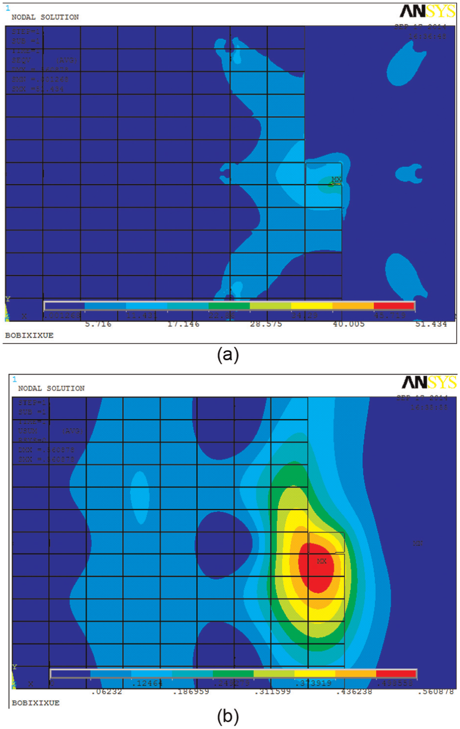
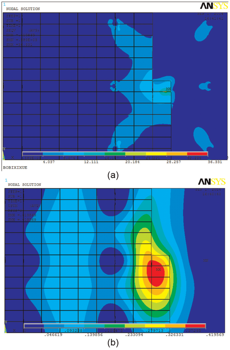
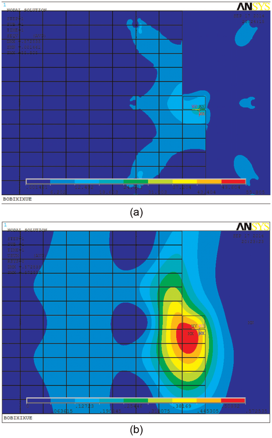
(a) Stress of sheet considering cutting heat and (b) deformation of sheet considering cutting heat.
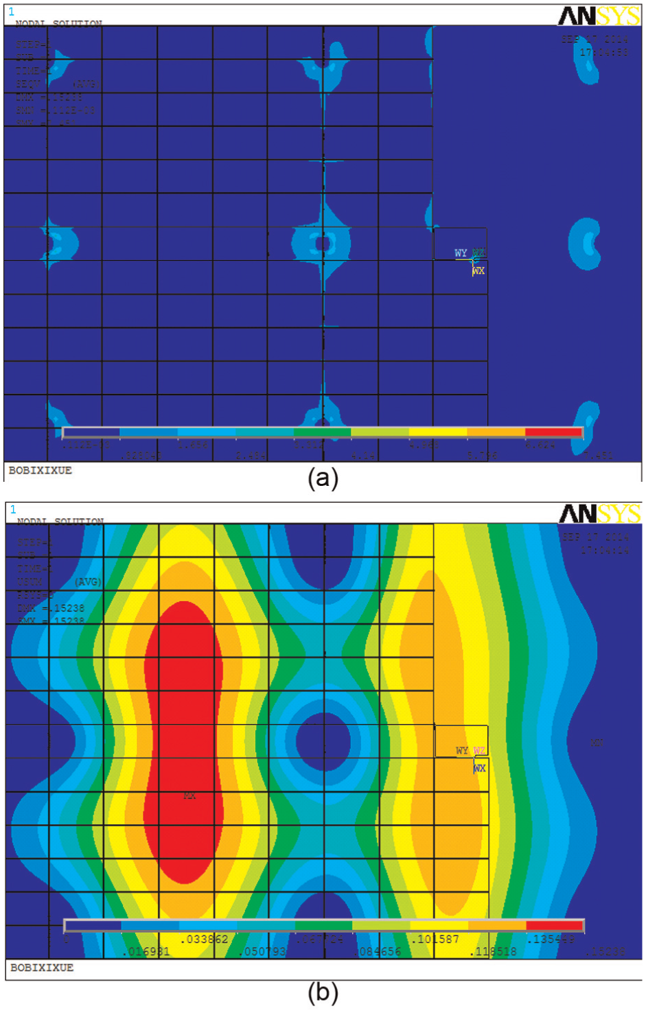
(a) Stress of sheet without considering cutting heat and (b) deformation of sheet without considering cutting heat.
From Figures 12 and 13, it is obvious that the cutting heat has great effect on maximal stress and deformation of grid sheet. In fact, maximum stress is 7.451 MPa in Figure 13(a) as against 36.331 MPa in Figure 12(a), and the maximum deformation in Figure 12(b) is 0.4196 mm as against 0.1524 mm in Figure 13(b). In addition, cutting heat greatly changed the distribution of deformation. Without considering cutting heat, the main deformation locates at the area with low rigidity. On the contrary, the main deformation locates around the cutting center with cutting heat considered.
FEA of grid sheet under different processing schemes
To investigate the effect of processing schemes with different cutting parameters on the behavior of grid sheet, stress and deformation of grid sheet under several cutting parameters are analyzed. Considering engineering practices,
(a) Stress of sheet with a cutting speed of 753 m/min and (b) deformation of sheet with a cutting speed of 753 m/min.
(a) Stress of sheet with a feed per tooth of 0.3 mm/z and (b) deformation of sheet with a feed per tooth of 0.3 mm/z.
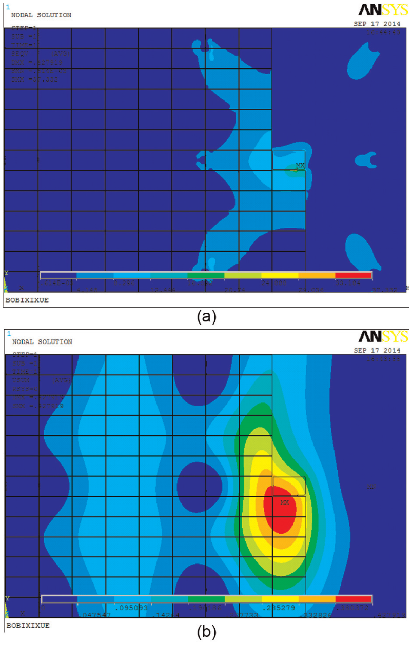
(a) Stress of grid sheet with a radial depth of cut of 8 mm and (b) deformation of grid sheet with a radial depth of cut of 8 mm.
Different cutting speeds
As shown in Figure 14, when cutting speeds of the processing scheme increases from 603 to 753 m/min (which is determined from engineering practice and equal to spindle rotation speed between 16,000 and 20,000 r/min) while other parameters are kept the same as Figure 12, maximal stress and deformation of grid sheet increased from 36.331 MPa and 0.4196 mm to 36.564 MPa and 0.4245 mm, respectively. Despite cutting force decreases with increasing cutting speed according to the cutting force model equation (11), cutting heat increases a little more with increasing cutting speed. Combination of these two effects leads to a small increase in stress and deformation.
Different feeds per tooth
As shown in Figure 15, when feed per tooth of the processing scheme increases from 0.1 to 0.3 mm/z (other parameters are kept the same as Figure 12), maximal stress and deformation of grid sheet increased from 36.331 MPa and 0.4196 mm to 37.332 MPa and 0.4279 mm, respectively. This is because both cutting force and cutting heat increase with increasing feed per tooth.
Different radial depths of cut
As shown in Figure 16, when radial depth of cut of the processing scheme increases from 6 to 8 mm (other parameters are kept the same as Figure 12), maximal stress and deformation of grid sheet increased obviously from 36.331 MPa and 0.4196 mm to 55.805 MPa and 0.5725 mm, respectively. This results from the increase in cutting force.
Conclusion
Unreasonably selected machining parameters in high-speed milling usually lead to notable stress and deformation of thin-wall structure grid sheet. Modeling the machining process of this kind of workpiece to predict its behavior is an essential development to evaluate processing scheme and optimize the cutting conditions. Therefore, a thermal–mechanical coupled FEM model which provides a convenient and flexible platform to set the size of grid sheet, type and size of grid and cutting parameters, to obtain the knowledge of milling process, was established.
Based on this FEM model, two analyses with and without considering cutting heat were compared. It was found that cutting heat causes great increase in magnitude of maximal deformation and stress that is undesirable, and it also changes the distribution of deformation and stress. Therefore, cutting heat could not be excluded from the analysis. With cutting heat considered, some analyses on processing schemes with different levels of machining parameters were done, and it shows that maximal stress and deformation of grid sheet increase little with the increase in cutting speed and feed per tooth, but far more with radial depth of cut. Therefore, to enhance machining quality of grid sheet, engineers should pay more attention to the selection of radial depth of cut.
Footnotes
Declaration of Conflicting Interests
The author(s) declared no potential conflicts of interest with respect to the research, authorship and/or publication of this article.
Funding
The author(s) disclosed receipt of the following financial support for the research, authorship, and/or publication of this article: This research is sponsored by the National Key Technology R&D Program of China (2012 BAF01B07).