
Abstract
This article presents a number of novel approaches for deriving intelligence from the parameterisation of computer-aided design models to assist the engineer in making manufacturing-related decisions. During the design process, a disjoint can occur between the nominally defined computer-aided design feature parameters and the dimensions which govern manufacture and influence ease of product assembly. In this work, a link between the two representations is established, which simplifies the process of using the parameters defining the features in the computer-aided design model to make manufacturing-related decisions such as the allocation of dimensional tolerances or dealing with fit issues. It also offers insights about how the model should be parameterised to provide the optimal model utility from the designer’s perspective with respect to the manufacturing domain.
Introduction
Historically, the Digital Mock-Up (DMU) has been a CAD based, virtual prototype which is central to the virtual aspects of the product development process. It typically represents the overall product as spatially positioned CAD geometry representing individual components and complete assemblies. Such models are powerful design tools 1 which can be used for verifying and validating product functionality, assembly and fit, maintainability, kinematic performance and data visualisation throughout the product life cycle.2–4
However, CAD models are usually little more than virtual, geometric representations of the nominally defined product parts. Assemblies are commonly only the parts in spatial position relative to each other, with their relationships captured only in the model hierarchical tree structure. Such CAD models do not capture the full impact of sources of assembly variation 5 based on ‘real part’ sizes or ‘physical build’ requirements. This means that the manufactured, assembled product will almost certainly deviate from that represented in the DMU assembly, thereby depleting its value in a manufacturing planning context. Therefore, the DMU, although an important design tool, does not play as full a role as it might in informing the design with regard to manufacturing or assembly variations, and a technical gap still exists between the virtual and actual domains during product design and realisation.
In this article, a novel method to link and derive new understanding between CAD model parameters and manufacturing attributes is established. The approach is first demonstrated for a simple problem to explain the mathematical principle. Having established the approach, further concepts are proposed to make evident how the choice or method of parameterisation of a CAD model can be used to derive knowledge useful for manufacturing decisions throughout a product life cycle.
Background
While CAD systems are central to the product design and manufacturing planning processes, it has been suggested they are not fit for purpose when it comes to representing design geometry in the advanced manufacturing era.5,6 Dimensional control is usually only considered when the design is complete, 7 at which stage 85% of the design’s life cycle costs have been committed as a result of decisions already made, and the cost of any further change increases exponentially. 8 With industry’s outlook of using DMUs earlier in design, giving it a new role for analysis, optimisation and simulation,9,10 it is important to address the challenges associated with capturing usable manufacturing data in a CAD system.
To address the inherent inconsistency between the very precise, nominally sized, CAD representation and the highly variable and dynamic manufacturing and assembly domains, a body of research has grown up around the representation of non-geometric information in CAD systems. Examples include the Lightweight Model with Multi-layer Annotation (LIMMA) 11 and approaches to transfer a richer set of information between different platforms and companies in the form of standards, for example, ISO 10303-239:2012. A body of research specifically related to assembly and manufacturing variability concentrates on more effective ways of representing tolerances within CAD models. Such research has produced methods to create ‘tolerance zones’12,13 as separate entities on the CAD model. Xu and Keyser 13 use model features and defined tolerances to optimise the model dimensions of a two-dimensional (2D) part. Geis et al. 12 directly represent tolerances on the three-dimensional (3D) model within the CAD system by transforming ISO standard tolerances defined on the model, to vectorial tolerances on feature surfaces. Chan et al. 14 represent realistic geometries directly in the CAD system using a combination of nominal CAD geometry, variational geometry and fractal geometry.
Current technological capability still requires relatively mature design definitions before manufacturability can be considered from a simulation point of view using statistical methods. Nigam and Turner 15 review the various approaches for statistical tolerance analysis. Chen et al. 16 present an up-to-date review of 3D tolerance analysis methods. Typically, tolerance analysis methods are applied after the CAD model has been completed when vector loop or matrix methods17,18 (e.g.) are applied. Algorithms have also been developed 19 for the creation of more realistic part forms for use in dimensional and geometric tolerancing, but again these are applied after the base geometry has been completed and the opportunity to make key component parameters inform the work of the designer may have been missed. By the time a mature design is ready for comprehensive analysis using commercial computer-aided tolerance analysis tools,20,21 the design will have already been constrained by the preceding design activities.
Thus, there are currently no self-contained or intrinsic methods within a CAD system which defines how a DMU will provide the designer with the information required to make manufacturing-related decisions. CAD functions cover the assignment of tolerances in notational form based on user knowledge and process capability documents, but there is no provision for the use of the 3D geometry itself to generate and update this knowledge as a design evolves, nor to make use of this knowledge in informing other decisions which are made. The principles defined and advocated by Price et al. 22 reinforce the view presented here that when real part geometries inevitably deviate from their CAD representation, the product assembly will perform differently when compared to any analysis completed using a DMU.
Hence, the research herein aims to exploit the geometric and parametric functionality of modern CAD and DMU systems. By focusing on the front end of the design process when the model geometry is created, the objective is to select appropriate CAD parameterisation strategies and have the CAD parameters effectively drive the consideration, development, and update of assembly tolerances as the design evolves, using functions which are intrinsic to the CAD modelling process. The approach does not aim to make statistical methods in tolerance design redundant, but it has the objective to open the opportunity for considering part variation earlier in the design process.
CAD feature selection and parameterisation
CAD platforms now offer such a rich set of feature types that there are usually many possible features, or combinations of features, which can be used to create the same resulting shape. Figure 1 shows a simple model of a block with multiple hole features created in the Siemens NX environment.
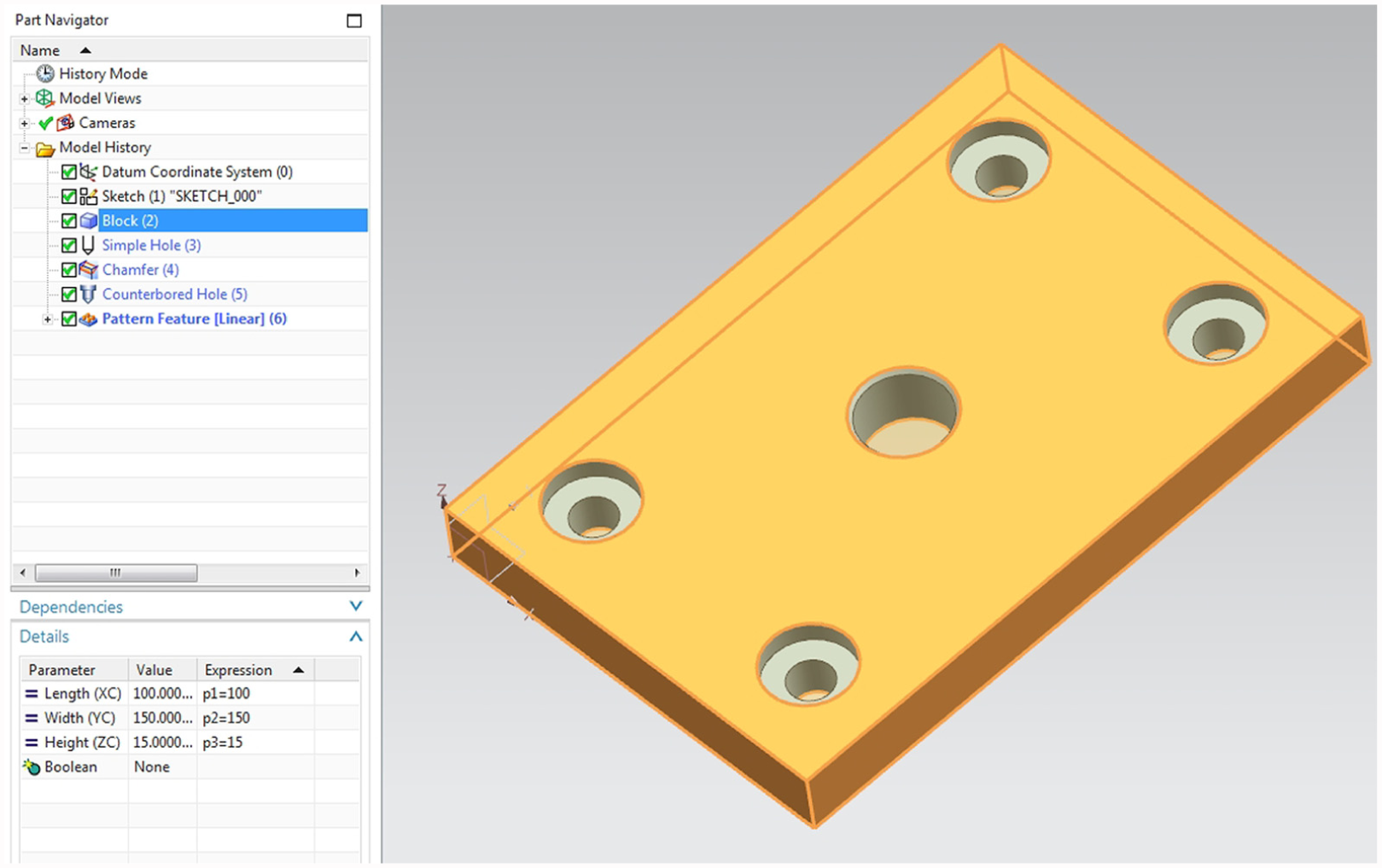
CAD model with multiple features and block parameters (NX environment).
The feature tree has been included showing the block, simple hole, chamfer, counter bored hole and pattern features which were used to create the model. The parameters associated with the block feature are also identified. It is evident that even a simple model will contain multiple features each with their own set of contributing parameters. Figure 2 shows how the block feature can be created using three different methods, (a) origin and edges as per Figure 1 (three parameters), (b) two points and height (single parameter feature), (c) two diagonal points (zero parameter feature). Each drives the creation of the same basic shape, but the subsequent shape variation, and the method of achieving it, will differ depending on the method selected.
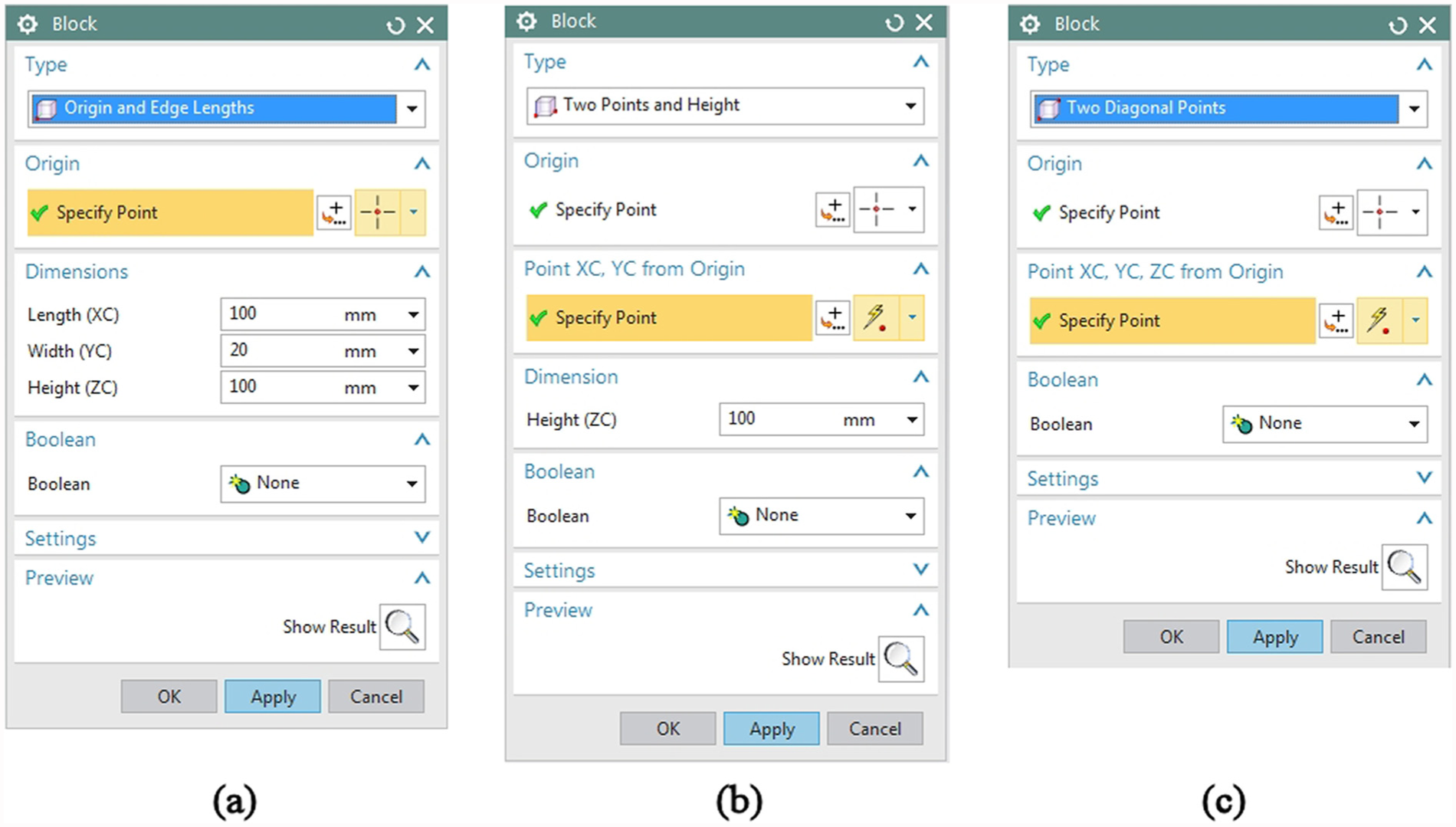
Creation of block feature with different creation methods: (a) origin and edge lengths, (b) two points and height and (c) two diagonal points.
For example, Figure 3(a) shows three different methods for how an initially cylindrical component can be defined in a CAD system. In the left hand model, a circle is extruded which constrains both its profile to be circular and profile along its length to be constant. In the centre model, a circle is modelled as a spline through control points which is extruded. This time the profile is not constrained to be circular, but the profile along its length is constant. In the right hand model, a sketch defining the axisymmetric cross section is revolved to define the component geometry. This method allows the model to evolve such that the profile will be circular at different points along its length, but the diameter can vary in this direction. Figure 3(b) shows the updated shapes when using the different parameters available.
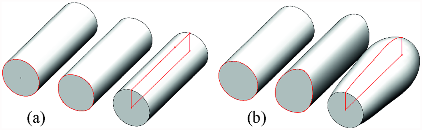
Different parameterisations of an initially cylindrical component: (a) the same initial models built using different parameterisations and (b) the updated models based on the different parameterisations.
These examples demonstrate the vast range of options available to create CAD geometry and how the parameters used to generate the geometry dictate how its shape can evolve. However, current CAD model parameterisation strategies are not systematically defined using the dimensions required to make the parts or critical features reflecting part geometry variability or those required to achieve an accurate assembly dimension. Even if a designer bears this in mind when modelling features and down selects the appropriate parameters, the CAD functions will not automatically update key dimensions to represent the key changes that are inevitably applied to the model over time.
Mapping parametric modelling and manufactured dimensions
Thus far, it has been argued the way current feature–based CAD systems construct shapes means that without careful consideration of what features to select and parameterisation strategy to employ, a disjoint can occur between the CAD parameters and the dimensions used for manufacture. For example, Figure 4(a) shows an exemplar component. This reasonably simple but representative component cross-section has been selected to enable a clear illustration of the proposed approach. Having illustrated the approach, subsequent work can present the challenges associated with more complex assemblies in which the number of model parameters and critical manufacturing features can introduce additional challenges. For such models, challenges associated with parameter interdependence become important and represent another body of research currently underway.
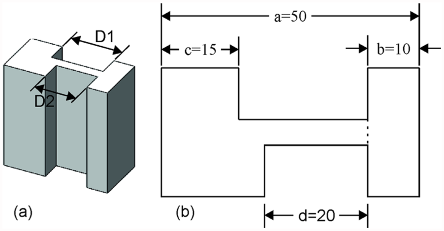
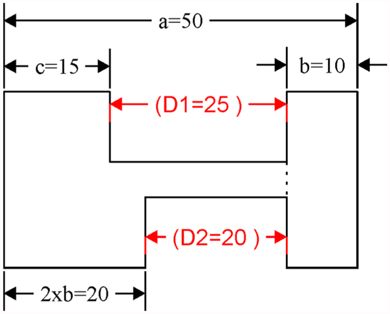
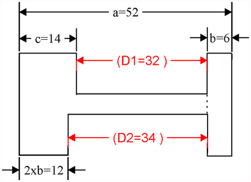
A CAD model constructed such that the parameters which define it do not match the dimensions used for manufacture: (a) isometric view and (b) section view.
Returning to the simple example, let us assume that the dimensions which are to be considered when assessing the performance of the component (including manufacture) are D1 and D2. For brevity, the other dimensions including the vertical parameters and dimensions are ignored. Figure 4(b) shows the sketch used to create the component in the CAD system, which is defined using a range of dimensional parameters, but those which impact D1 and D2 are a to d. At this stage, it is important to note that one of the critical dimensions for manufacture D1 is not represented directly by CAD parameters a to d.
The difficulty with this is that while the design intent 22 will be considered in terms of the functional dimensions which will be used to manufacture the part (D1 and D2), the designer must use the CAD parameters (a to d) to implement any design updates to these dimensions. This means the processes for updating the model are not straightforward.
For situations such as this, the designer needs access to information about how the parameters which define the features in the model relate to the manufacturing dimensions. For example in Figure 4, the information that the designer needs to modify one of, or a combination of a, b, c or d in order to modify D1, may not be obvious. This is especially true if the model is complex and there are potentially hundreds or thousands of features to choose from, each with their own underlying parameter set. Another reason for the difficulty is that the CAD model may have been originally created by another designer and the method of construction may not be easily interpreted. Even if the designer determines that a, b and c are the important parameters for modifying D1 (varying d does not impact D1), their impact on other manufacturing dimensions in the model is not immediately clear.
To address this, a solution is proposed here in which a mapping is generated between the manufacturing dimensions in the model and the feature parameters using a sensitivity approach. For each feature parameter in turn, its value is perturbed and the resulting change in each manufacturing dimension is measured. To normalise the effect, the change in the manufacturing dimension is divided by the perturbation size.
A sensitivity matrix, S, is generated containing each manufacturing dimension and feature parameter combination. Each row in the matrix represents the key manufacturing attributes, whereas each column represents the feature parameters. For the model in Figure 4, the sensitivity matrix, Equation (1), is where row 1 represents D1, row 2 represents D2, and the columns represent parameters a to d, respectively
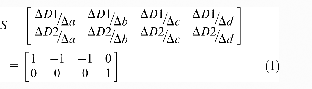
This sensitivity matrix alone provides a range of useful information about how to use the feature parameters to modify the manufactured dimensions in the model. For each row in the sensitivity matrix, where a parameter has a non-zero value, this indicates that the feature parameter (a, b, c, d) represented by the column can be used to control the key manufacturing attributes (D1, D2). It also allows the relative level of control imposed by the different parameters to be quantified.
Should the matrix have a zero row, it indicates that there are no feature parameters in the model that can be used to control the key manufacturing attribute, in which case the designer needs to rethink how the model is parameterised. Such a scenario is rare if a robust modelling strategy has been used and all of the features have been fully defined. Should the matrix have a zero column, it indicates that the parameter represented by the column does not have an effect on any of the manufactured dimensions in the model. This information can serve to identify parameters which can be modified by the designer without having an impact on the model’s manufactured dimensions, but can also be used to significantly reduce the size of the challenge faced by the designer. This also demonstrates the need for a measure of the parameterisation’s ability to influence the key manufacturing dimensions.
By specifying the mapping between the manufactured dimensions and the feature parameters in the form of a sensitivity matrix, it becomes clear how the parameters can be used to control the manufactured dimensions in the model.
With respect to Figure 4, the fact that the first to third columns of equation (1), representing parameters a to c, have a sensitivity value for D1 and zero for D2 means that these parameters can be used to control D1 without impacting D2. Likewise, the fact the fourth column of equation (1), representing parameter d, exhibits the same property for D2, means that it can be used to control it without impacting D1. From this, it should be clear to the designer how to proceed when modifying D1 and D2 in the CAD model.
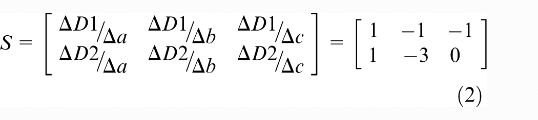
Figure 5 shows an alternative parameterisation for the model in Figure 4(a). For the model in Figure 5, the sensitivity matrix created using the same process as for the previous example is shown in equation (2)
A sketch defining a CAD model constructed such that manufacturing dimension D2 cannot be modified without affecting D1. Note that D1 and D2 are not part of the parameterisation.
From the sensitivity matrix, it is clear that for the parameterisation strategy used for the sketch in Figure 5 it is not possible to modify D2 without changing either parameters a or b, or both. However, changing parameters a or b without considering the effect on D1 may cause a potentially unwanted change to D1. Should it be unclear to the designer how to modify the feature parameters to achieve certain changes in the manufactured dimensions, then the mapping provided by the sensitivity matrix can be used to provide a solution.
As a simple demonstration, the product of the inverse of the sensitivity matrix, S −1, and the required change in each manufactured dimension, ΔMD (here assumed to be an increase in length of 7 mm in D1 and 14 mm in D2), returns the change in parameter values to achieve the required geometry, equation (3), where Δa, Δb and Δc are the parameter adjustments to cause the desired changes in the manufacturing dimensions
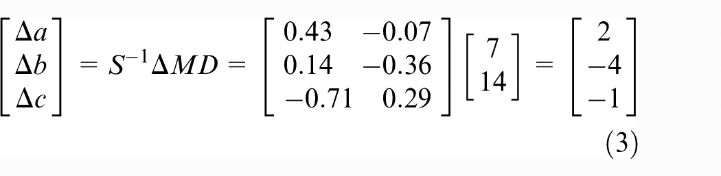
Note that for a non-square sensitivity matrix, the Pseudo Inverse 23 of the matrix can be used for the analysis. Applying these parameter changes to the model in Figure 5 gives the model in Figure 6. Clearly the ambition of changing both manufactured dimensions to specific values has been achieved. Where the desired changes are not achieved, it would be an indication that the parameters in the model do not have a sufficient level of control over the manufactured dimension values to be able to specify them each individually. In such a case, the choice of parameterisation would need to be reconsidered.
Parameter dimensions a, b and c updated to give desired change in manufacturing dimensions D1 and D2.
Figure 7 shows the section view of an assembly model comprising 33 parts, with the Key Product Characteristic (KPC) dimensions X1 to X4. In total, the assembly and its parts are defined by a total of 1875 parameters. Using the proposed sensitivity analysis approach, which took 40 min to run on a standard desktop machine, it was identified that the sensitivity matrix comprised zero columns for all but 34 parameters. This meant that when considering and modelling assembly variation, these 34 parameters were all that needed to be considered. In this particular example, it was identified that X1 and X4 could be controlled independently of the other KPCs (i.e. the rows representing these KPCs had the only non-zero value in the column representing a particular parameter). It was also identified that KPCs X2 and X3 were controlled by the same sets of parameters. Thus, in this case, multiple parameters would have to be changed to achieve specified dimensions for these two KPCs.
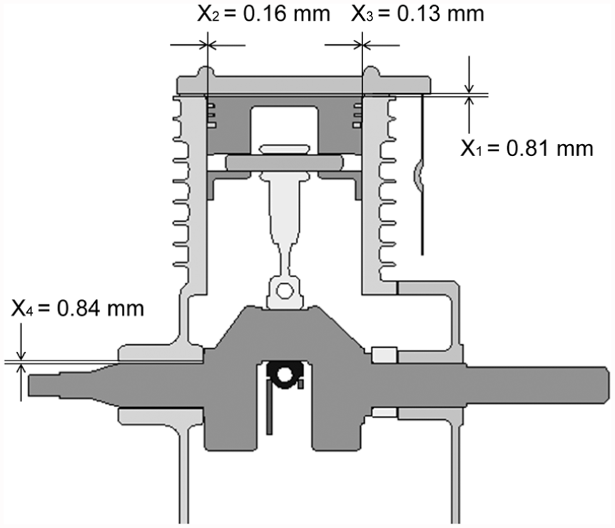
Assembly model with four KPC dimensions.
These examples emphasise the importance of model parameterisation and the way it is planned, executed and exploited. The process is robust because it uses the constraints modeller and measurement tools within the CAD package to determine the mapping between the measures of interest and the parameters in the model. By automatically deriving mapping information between the manufacturing features and the parameters which define the features in the CAD model, the relationship between design and manufacturing dimensions is clearer. As a consequence, there is more opportunity to use the CAD model to include manufacturing in design decisions.
Applications
Thus far, mapping the CAD feature parameters to the manufactured dimensions has been discussed. The approach described is applicable when considering a number of aspects of the design which are important for manufacturing.
Fit
As described by Zubairi et al., 10 one of the key verification roles of a DMU is to ensure the fit of the different components in the assembly. Most CAD platforms have interference detection capabilities which can identify when two or more components in the model are occupying the same point in space (Figure 8). If this interference is unintentional, then it highlights to the designer that design modifications (or corrections) are required which can mean a design update before the components are manufactured, or planning a subsequent manufacturing operation. Failure to account for this may result in either poor product performance or a requirement for rework before component assembly can take place.
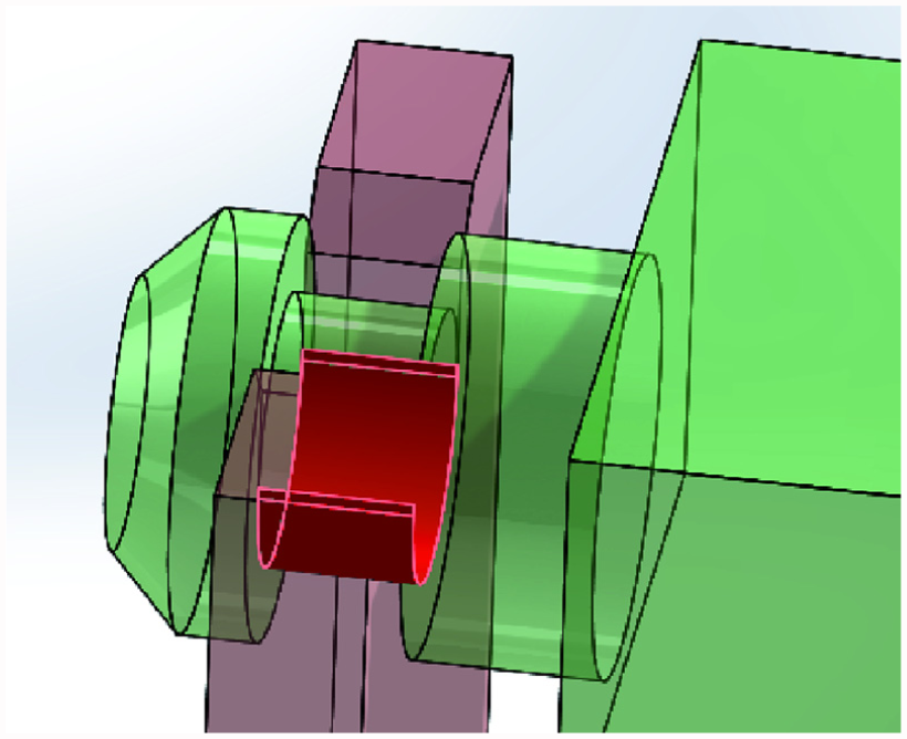
Interference between two components (in red).
When interference is identified, the designer can use an approach similar to that described previously, only the rows in the sensitivity matrix will represent the interference at specific locations, to first map the impact of the feature parameters to the interference volume and then to predict the change in feature parameters required to eliminate the clash from the model. To achieve this objective, which is the equivalent to ΔMD in equation (3), is to reduce the clash in the model by an amount equal to the initial interference volume. A range of other manufacturing associated values may be considered in the same manner, for example, mass of the assembly or second moments of area.
Tolerance allocation
As described in section ‘Background’, CAD systems are limited in their functionality to effectively assign tolerances, creating a superficial link between design and manufacturing. The work of Wan Din et al. 24 uses the parameters of the CAD model to allocate dimensional tolerances on feature dimensions. Equation (4) shows the link between KPC, for example, tolerance dimension, and Key Control Characteristics (KCC), for example, feature dimensions. Although not represented directly in the equation, the sensitivity of the parameters of the features to the key product dimensions is used in the creation of the pseudo sensitivity matrix ‘[ψ]+’, which may then be used to automatically assign dimensional tolerances to the features as

This method demonstrates the application of parameterisation in tolerance allocation; however, it only deals with the dimensional tolerances associated with the size control of features. A more pressing matter acknowledged in research is that of representing and analysing form deviations in parts, which can have a significant effect on the functionality of an assembly when their cumulative effect is considered. 14 The proposed mapping approach is not constrained to size-related model parameters but can consider parameters directly associated with form and shape.
Parameterisation effectiveness
In section ‘CAD feature selection and parameterization’, it was noted that in certain situations the parameters may not be able to achieve the desired changes in the model. Parametric effectiveness 25 is a measure which rates the quality of the parameters in a model for their ability to change the design in the optimum manner. It has been described in an optimisation context, but when considered in the context of manufactured dimensions a model with high ‘Parametric Effectiveness’ could be considered to be one with the ability to set each manufactured dimension in the model to its optimum value. This requires that a combination of parameters has the ability to control each manufactured dimension independently of the others. The inability to achieve this means that trade-offs will be required when specifying the values of the final parameters in the design. Where this is the case, it will indicate a parametric effectiveness <1.
Robinson et al. 25 suggest that when the model is parameterised so that it has a low parametric effectiveness, the designer should consider changing the parameterisation before attempting to optimise the model. A simple test to determine the ability of the parameters to control a key manufacturing attribute might be, for each parameter in turn, to attempt to change the value of the manufactured dimension by a set amount without changing the value of any other manufactured dimension. The approach described herein to compute the parameter change to achieve a desired change in manufactured dimension values illustrates how parametric effectiveness with respect to manufacturing assembly may be calculated and used in modelling decisions.
Furthermore, ‘Dimensional addition’ has been proposed as the optimum process for model creation when embedding design intent. 19 Dimensional addition is a process for geometry creation which allows flexible geometry models to be generated in such a way that they can be easily updated, minimising tedious and costly rework and updates. It is suggested herein that the principle of parametric mapping and the assessment of parametric effectiveness should be used as a rationale for selecting the parameterisation of a model during the dimensional addition process. As already stated, a parameterisation with a high parametric effectiveness is one that allows each manufactured dimension in the model to be set to a specified value without constraining the values of the others.
Discussion
This work has presented straightforward but powerful methods for extracting intelligence useful for manufacturing applications from the parameterisation of a CAD model. The methods add utility to the component data as smarter use of modelling parameters allows for improved consideration of manufacturing dimensions as a design evolves. In developing and exploiting these methods within individual CAD building blocks, the potential is improved for the creation of future models which take manufacturing-based parameters into account. The example applications, Figures 4–7, have derived a sensitivity map as a means of linking and understanding the relationships between the feature parameters in the CAD model and the values of interest for manufacturing the components and assembling the final product.
By building the design models in this way, the CAD modelling environment will become more useful than it is currently, providing greater control over different aspects of the product beyond design into manufacture. This in turn enables the use of conceptual models for the consideration of manufacturability early in the development cycle when large changes in configuration may occur. By basing the choice of parameters and the model building process on the manufacturing considerations, advantages include enabling the quick analyses of alternative manufacturing processes while maintaining structural/system design intent.
Also, the goal is to select the parameterisation of the model based on its design intent. This opens the avenue for the concept of parametric effectiveness to be used as a measure of how well design intent is embedded in the model. This should provide the building blocks for a smarter DMU, where unlike some of the existing tools manufacturing constraints can be enforced when editing the model. This therefore should make the process of linking the design intent to different attributes of the model construction easy and transparent.
Conclusion
From this work, the following conclusions are drawn:
The parameterisation of a CAD model has a vital role to play in allowing manufacturing to be properly considered during design.
The parameterisation of a CAD model can be used to derive intelligence useful for controlling manufacturing aspects of a design.
Parametric effectiveness has a role to play in determining the usefulness of the parameters in the model for controlling manufacturing aspects of a design.
Footnotes
Declaration of conflicting interests
The author(s) declared no potential conflicts of interest with respect to the research, authorship and/or publication of this article.
Funding
The author(s) disclosed receipt of the following financial support for the research, authorship, and/or publication of this article: The authors would like to thank the EPSRC and the Department for the Economy (DfE) for providing funding for the related PhD studentships.