
Abstract
Start-up energy consumption is a vital component of machine tool energy consumption. In some cases, such as forecasting and quota planning for energy consumption, the start-up energy consumption must be acquired before practical machining, so that the determination of start-up energy consumption before machining is indispensable. However, the start-up energy is usually neglected or regarded as a part of the no-load energy because its characteristics are complicated and unavailable by theoretical computing models. These treatments could result in significant errors under certain working conditions and could also undermine increasing the accuracy requirements for energy analysis. To close this gap, this article presents a method for determining start-up energy consumption based on specific databases consisting of data and functions. To use the database, the relative change in the rate of power is utilized to identify a start-up process, and a relation model between the start-up energy and the spindle speed is established. The energy consumed in the starting process is obtained by summing the energy consumption of each recording interval or by integrating the power function in its time domain. This experimental study proves that this approach has a relatively high accuracy. In addition, the analysis of its application shows that this method is practical for forecasting energy consumption of a start-up process, planning the energy quota for machining a piece of work in manufacturing and other purposes.
Introduction
Machine tools consume tremendous energy in large quantities and with poor energy efficiency, 1 which implies a great potential for saving energy. To date, research on the energy consumption of machine tools has become increasingly active and has already shown significant achievements.
Some researchers focus on the energy of the machining processes. For instance, Gutowski et al. 2 estimated energy requirements by an exergy framework and the material removal rate, ultimately providing two important strategies to minimize energy consumption by comparing specific electrical energy requirements of different machining processes. Li and colleagues3–5 developed an inverse model to characterize the relationship between the specific energy consumption and machining parameters for material removal processes through certain experimental methods and statistical modelling. Dietmair and Verl6,7 established a generic energy consumption model to forecast the energy consumption behaviour and analyse the energy efficiency of machines and plants after decomposing the whole energy consumption of a machine tool into its subcomponents. Liu et al. 8 established an energy transmission model and a power equation for the main transmission system of a conventional machine tool, which only provided a theoretical foundation for analysing the energy consumption of the main transmission system of machine tools. Wang and Liu 9 presented a systematic mathematical energy model of multi-source energy flows for computer numerical control (CNC) machine tools after analysing the power equation for each energy flow.
Generally, extensive work has been performed on the no-load power, the machining power and the overall power of machine tools, while start-up power always receives little attention because the regularity of the start-up power is complicated, its computing model parameters are difficult to acquire and its time duration is generally considered to be very short. Therefore, even the limited existing research about the start-up process treats the start-up process as a part of the no-load process 10 or even neglects the start-up process entirely. These treatments will lead to considerable errors with regard to machine tools that frequently activate their main spindle electromotors in a running state. For example, a turning machine tool without a clutch cuts a screw, which consumes considerable energy when the machine alternatively operates the main electromotor in positive and negative modes. In that situation, our test shows that the error is up to 78% when the start-up procedure is placed into the no-load mode. Moreover, Liu and Liu 11 proposed a method for the prediction of the whole energy consumption during the service process of a machine tool, which needs to have start-up energy consumption before the machining process.
Thus, this article presents a method for acquiring start-up energy consumption data based on specific databases consisting of data and functions. Once those databases and models have been constructed, energy consumption for any start-up process of any machine tool in a certain manufacturing system will be acquired without any measurement before machining when forecasting the energy consumption of machine tools or planning the energy quota of a work piece.
Definition of start-up energy
Definition of start-up process
According to Li et al., 12 the whole start-up process for a machine tool can be subdivided into the following phases:
Turn on the main power switch of the machine tool. In this phase, the machine turns into the idle mode with the electric control cabinet and fans activated.
The hydraulic system and the cooling and lubrication systems revive, preparing for starting up the spindle.
The spindle motor starts to accelerate the spindle to the target speed. This phase, when it comes into a steady state, is usually cited as the no-load mode.
Based on these phases, the start-up process defined in this article is the procedure where the spindle accelerates from zero to its target speed
Component-based description of start-up energy
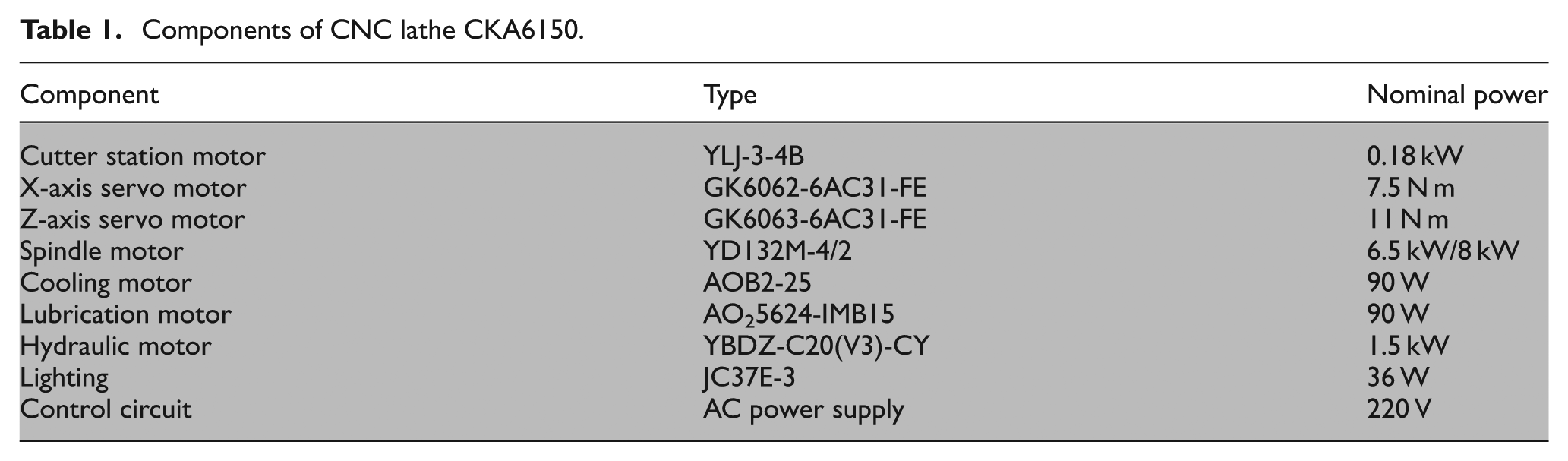
Energy is consumed to take the material to another state, 13 and the start-up energy is thus consumed to help move the spindle from the static condition to the rapid movement condition. Start-up energy in this condition consists mainly of fixed energy to ensure the readiness of the machine 12 and the spindle activating energy, which is consumed by auxiliary systems, servo systems, cooling and lubrication systems, hydraulic systems and the main transmission system of the machine tool. Those systems form a very large inertia system in machine tools, so the effects of the inertia of an attached tool or work piece are neglected. Undoubtedly, components participating in the start-up process vary with the type of machine, increasing mainly with the complexity of the machine tool. For example, dashed boxes in Table 1 briefly summarize the components of a CNC lathe CKA6150, which are tightly connected to ensure that the machine tool will start up.
Components of CNC lathe CKA6150.
Methods in the start-up process
Energy consumption of machine tools during the start-up process can be determined by the power demand and the time duration of this start-up process. In addition, the power profile of a machine process in Li et al. 12 indicates that the total power demand during the start-up process is the accumulation of individual power demands for each component. As for the investigation of the power demand, He et al., 14 Liu et al. 8 and Hu 15 have provided valuable information. Thus, this article will not investigate this information again. Instead, the time of the start-up process and the energy consumption during this process will be analysed in detail.
Background for the start-up process
According to the definition of the start-up process in this article, the start-up time can be defined as the duration where the spindle accelerates from zero to the target speed
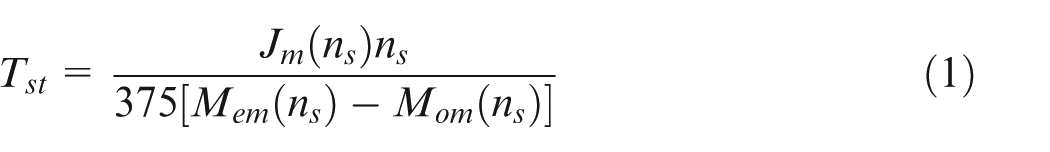
where
According to the model mentioned above, the relationship between the start-up time and the spindle speed is dominated mainly by the rotational inertia and the load of the motor. Meanwhile, those two factors are also able to be identified as a function of the spindle speed. As a result, the start-up time of machine tools can then be addressed as a function of the spindle speed included as equation (2), which lays a theoretical foundation for obtaining the start-up time for machine tools

The energy consumed by the main transmission system and auxiliary systems constitutes the energy consumption of the start-up process. Because the auxiliary systems are already in a steady state during the start-up process, their energy consumption can be considered constant. In this situation, investigation of the energy consumption of machine tools in this process naturally converges to the main transmission system.
Liu and Liu 1 have already established a dynamic power equation for the main transmission system, presented as equation (3)
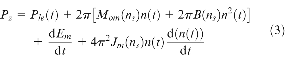
where
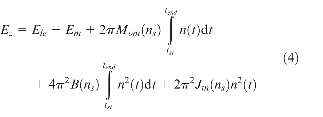
with
The models show that these parameters in equations (1) and (5) will be fixed after the machine tool and the target speed are settled. Thus, for a certain machine tool, the start-up time and its energy consumption are affected only by the spindle speed, which provides a beginning for analysing the start-up energy. Moreover, it is unrealistic to calculate energy consumption directly in those models because some parameters are unavailable. Thus, finding a practical and available method for determining start-up energy consumption for different machines will benefit the whole energy research area for machine tools.
Methods to determine the start-up time and energy
The method proposed in this article must first identify the start-up process. There are several definitions in this identification procedure. The recording interval of the acquisition device is set as
Two sets of boundaries in terms of the structure differences of machine tools are used to identify this start-up process. For the starting boundary, for conventional machine tools, when the machine connects to the grid, the spindle activates simultaneously. Therefore, before starting up the spindle, the whole power value
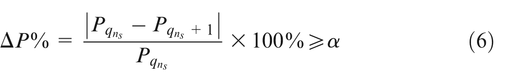
The parameter
Likewise, for the end boundary of a start-up process, when
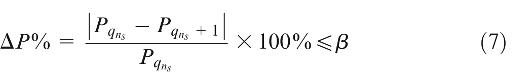
The parameter

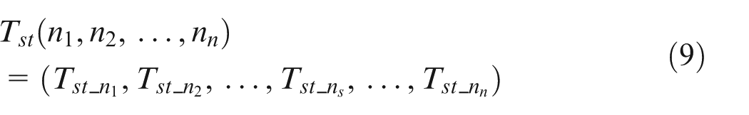
Generally, the whole start-up time of each spindle speed can be obtained by equations (6)–(8). For some step speed regulation (SSR) machine tools, the start-up time is summarized and stored in a database in a discrete way as in equation (9). Meanwhile, for those stepless speed regulation (SLSR) machine tools, the time duration for each start-up process is saved as a quadratic equation as in equation (10)

where
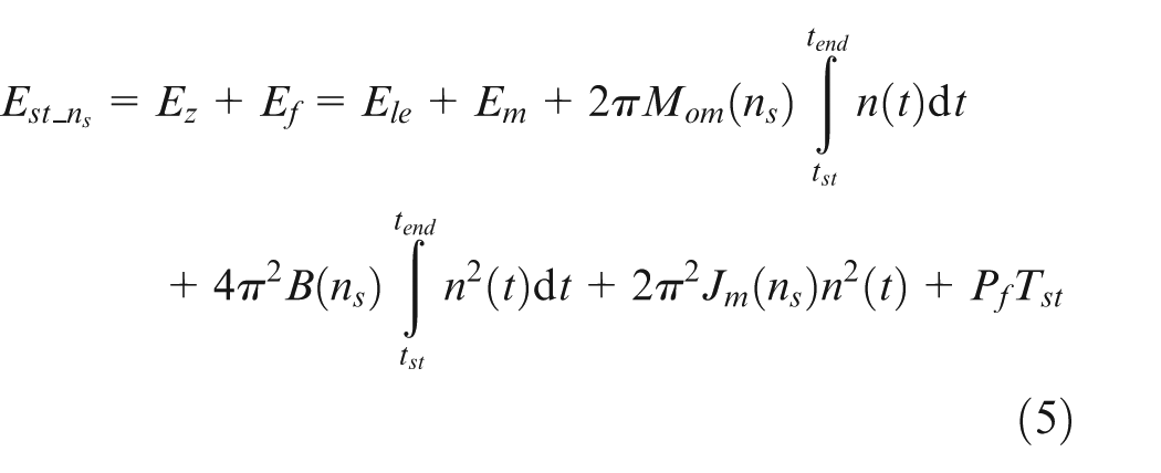
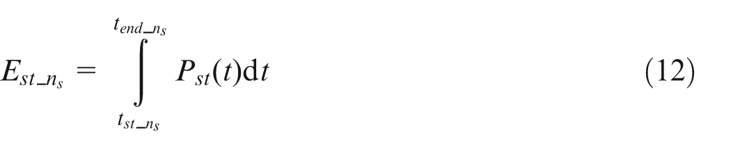
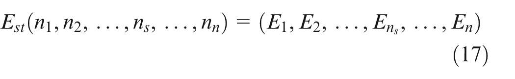
Progressively, the energy consumption within the region
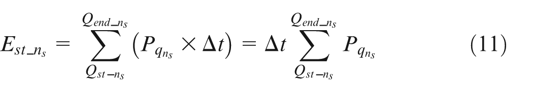
or
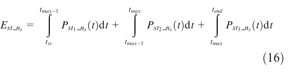
This power function is usually so complicated and lacking in regularity that a simple curve is not sufficient to fit it. In addition, considering that a peak power value exists for each speed, the fitting function is then ordinarily subdivided into three parts: a linear function, a Hermite interpolation function and a cubic function. Between the linear curve and the Hermite curve is the point
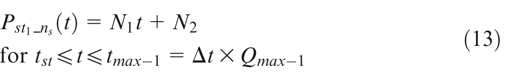
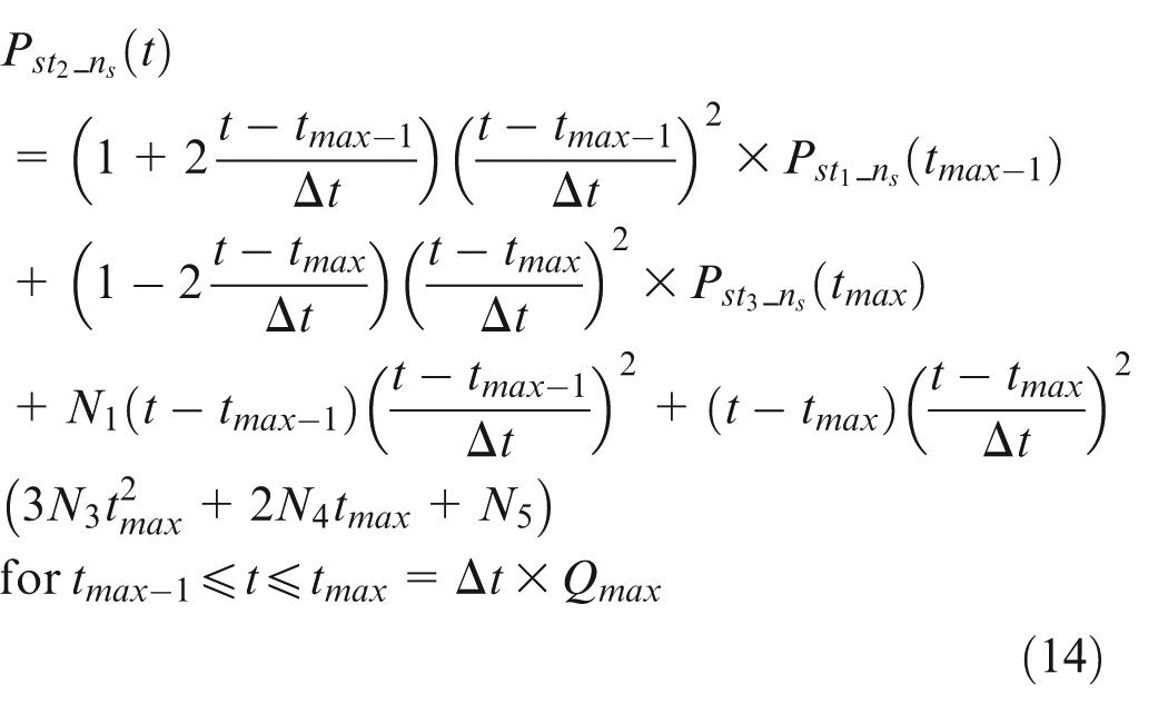
where
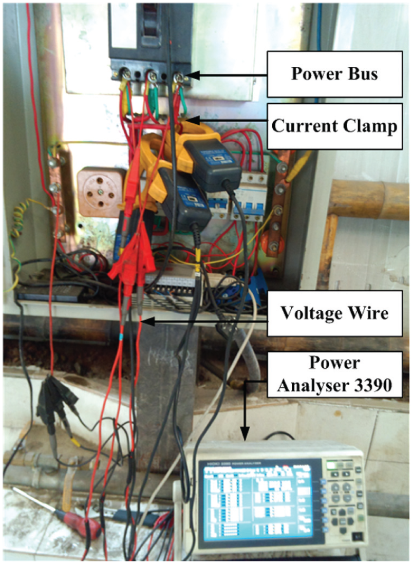
Like the time duration for the start-up process, energy consumption for each spindle speed of a machine tool can be determined either in a discrete way or as a quadratic function, namely, equations (17) and (18), respectively

where
The parameters acquired by equations (8)–(18) are easily stored in databases according to the type of machine tools and eventually retrieved to support the energy consumption prediction for machine tools and the energy quota planning of work pieces.
Experimental study
Design of experiments and measurements
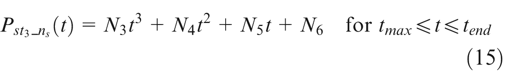
The method proposed in this article was initially derived from experiments. Hence, the precision of acquisition devices directly determines the accuracy of the final analysis. For this reason, a HIOKI power analyser 3390, produced by HIOKI E.E. CORPORATION (81 Koizumi, Ueda, Nagano, Japan), with 500 kHz sampling frequency and 50 ms data refresh rate was employed. To evaluate the total energy consumption of machine tools during the start-up process, a measuring point was situated at the power bus. Voltage signals, current signals and power factors were captured under the three-phase four-wire mode using three current clamps and voltage wires. Those signals were finally processed into power information by the HIOKI power analyser. Several software packages were utilized to process measured power data, namely, Microsoft Excel, Statistical Product and Service Solutions (SPSS) and MATLAB R2010a software. To ensure feasibility, this work analysed 12 machine tools covering 4 CNCs, 1 NC lathe, 1 NC milling machine, 2 conventional lathes, 2 conventional milling machines and 2 radial drilling machines. The experimental setup is illustrated in Figure 1.
Experimental setup profile.
The experiments were classified into two categories according to the speed regulation. First, in terms of SSR of machine tools, the target speeds
Results and analysis
Figure 2 illustrates the ability of the
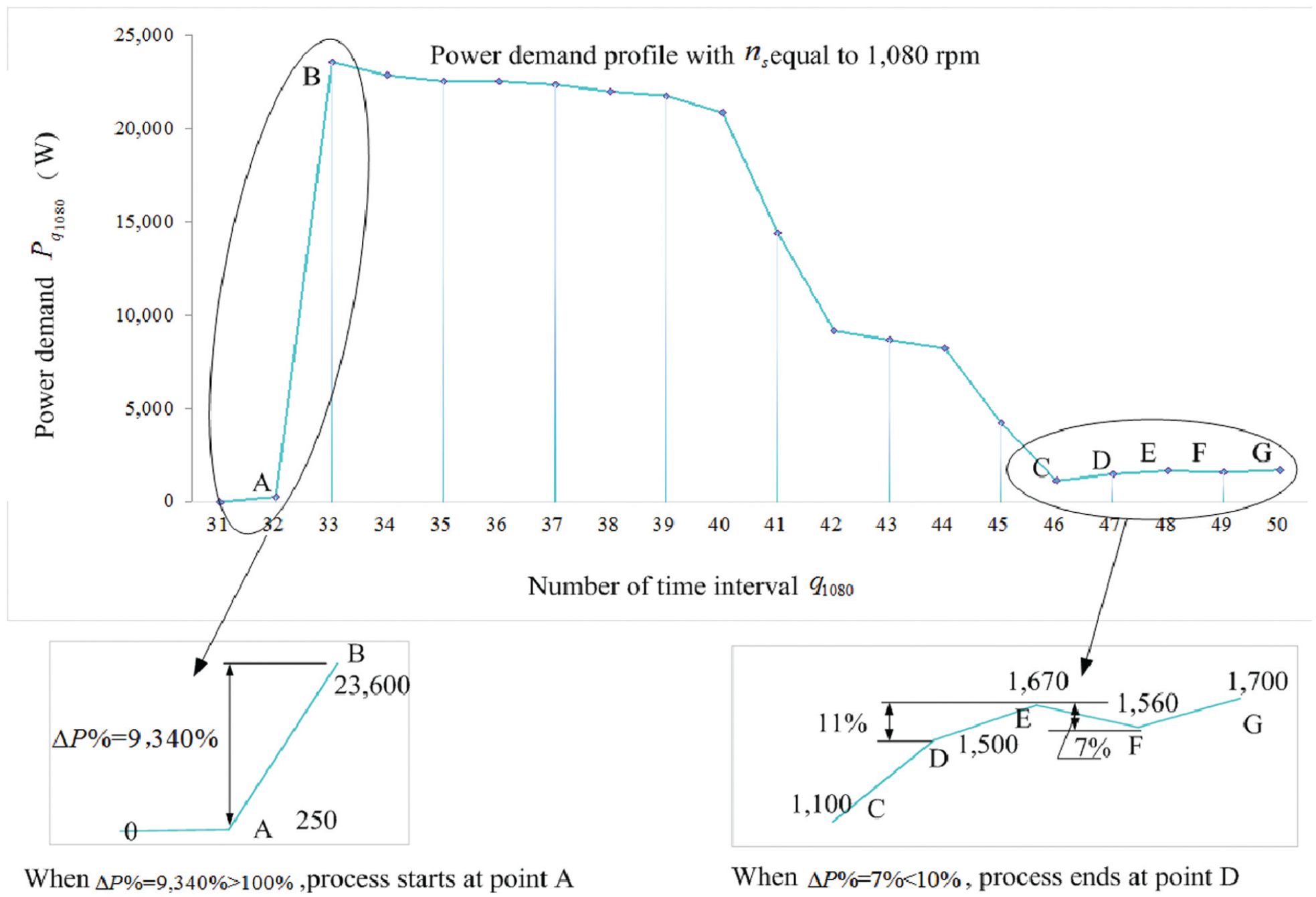
Procedure of identifying a start-up process for lathe C6132.
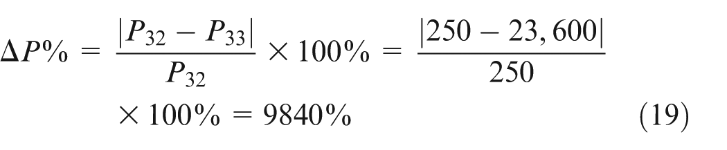
This percentage is somewhat larger than 100%, indicating that the spindle starts at point A, and the recording duration at this point is

After this point, the power changing rates fluctuate until the recording process reaches point E. From this point, rates remain lower than 10%, and according to the end boundary proposed in this article, the point exactly before E is the edge of this start-up process, which is the point D
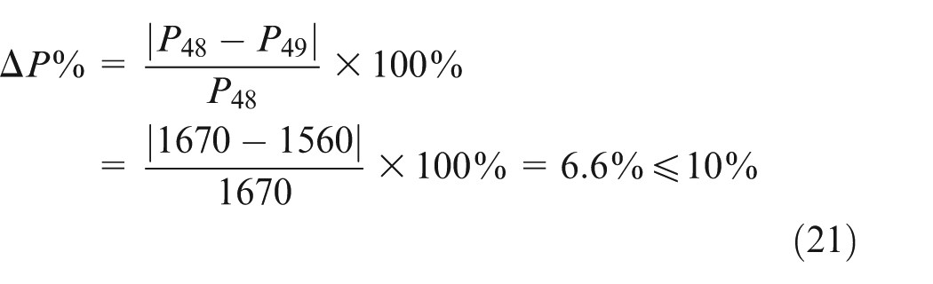
The recording duration to this point is

The time duration of the whole start-up process is clear with the value 750 ms according to the equation

Likewise, the start-up time for other spindle speeds of the lathe C6132 can be calculated. The results are summarized in Figure 3.
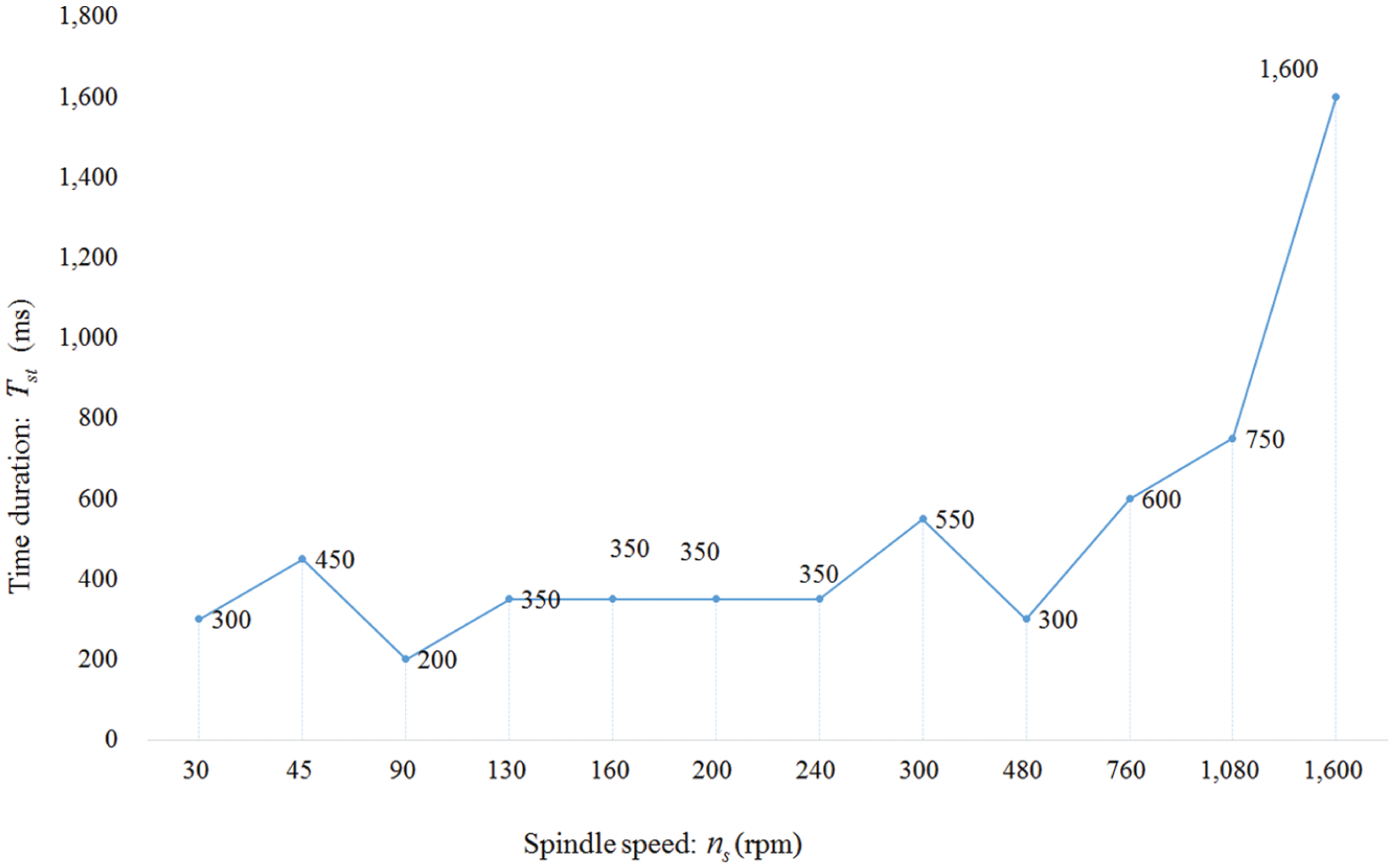
Start-up time for the C6132 lathe.
Energy within the start-up period of the C6132 lathe is calculated as equation (11) and summarized in Figure 4 in blue bars. Green bars describe the energy consumption calculated by an average no-load mode power instead of the transient start-up power. Clearly, using no-load power to replace the start-up power in calculating energy consumption will result in very large errors.
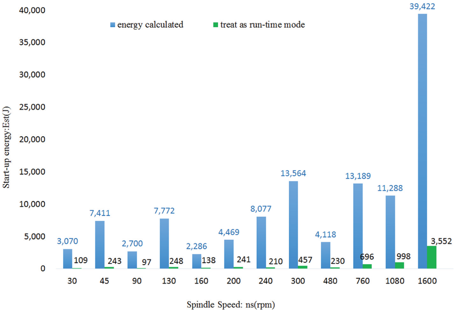
Energy consumption with different treatments.
To ensure the generality and the availability of this method, this method was applied on a highly automated machine centre BinShengMV-L900. The identification procedure for the start-up process of BinShengMV-L900 at 6000 r/min is quite similar to the procedure for C6132 at 1080 r/min, which is illustrated in Figure 5. According to Figure 5, the spindle activates at point D as the power changing rate at point D is larger than 100%
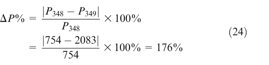
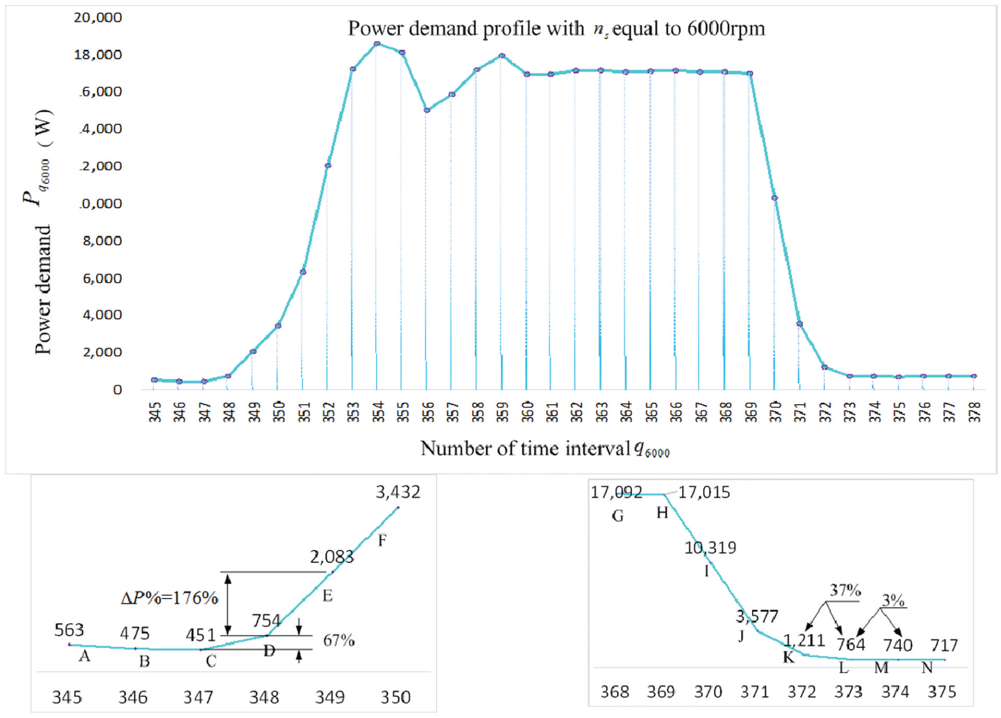
Procedure for identifying a start-up process for BinShengMV-L900.
Naturally, the recording duration is

To find the end point, the changing rate at point L is only 3%, which means that the whole start-up process ends at the point before L, exactly at point K
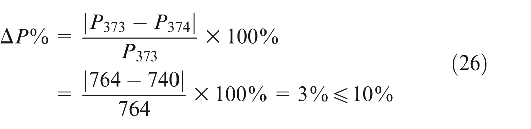
The recording duration until this point is

At this spindle speed, the time duration is

Differing from the conventional SSR machine tools, this centre can continuously shift its speed. As a consequence, the time duration of its start-up process is saved as a function of the corresponding speed. This relationship can be expressed using the SPSS statistical analysis package. The curve estimation function of SPSS provides 11 different types of models to determine the most authentic model, from linear to quadratic, from logarithmic to exponential. R2 and F values are used to evaluate the accuracy of each fit, as shown in Figure 6. The quadratic model shows an accuracy of over 97% and has a comprehensive advantage for fitting the time duration of the start-up process. Hence, the experimental results are concluded as equation (29) with an R2 of 0.974 and an F value of 722.266. The coefficient

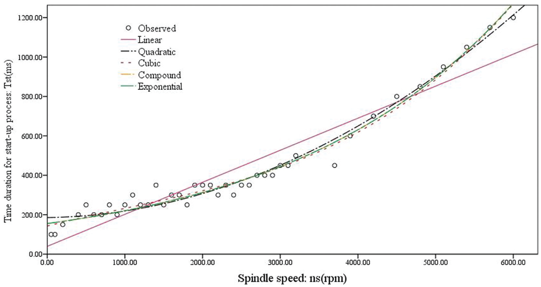
Fitted curves for duration versus spindle speed for BinShengMV-L900.
The energy of the start-up process for BinShengMV-L900 (Figure 7) illustrates a three-dimensional (3D) model of the start-up power information for this process. The blue portions in this figure represent the power in the steady state, the no-load power, when start-up processes are over. The power curve in Figure 7 does not peak at the beginning of the start-up process. Instead, a delay of 0.2 s after activating the spindle is observed. This phenomenon results mainly from the initial magnetization of the induction motor. 18
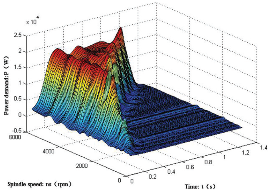
Power demand for the BinShengMV-L900 in the start-up period.
The achievement of its power function with the spindle accelerated to 6000 r/min exemplifies the applicability of equations (13)–(15), illustrated in equations (30)–(32) and Figure 8. The power demand in Figure 8 appears to show a slight slide near 0.3 s due mainly to the employment of an S-acceleration mode during the acceleration of the spindle, which agrees with the phenomenon presented in Figure 7
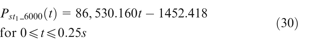
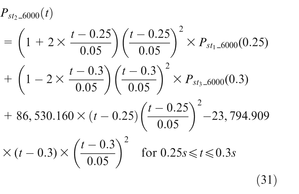
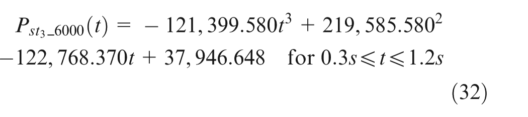
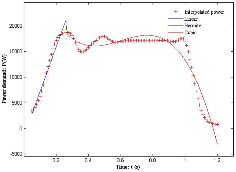
Power demand profile at 6000 r/min spindle speed.
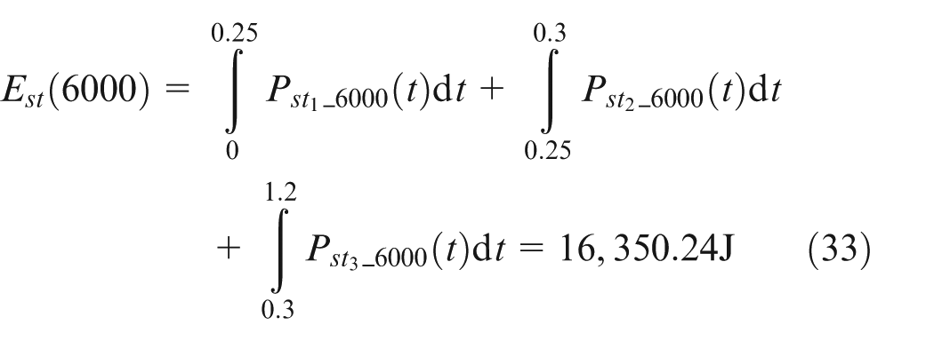
Therefore, energy consumption can be integrated in equation (33)
Start-up energy for the other spindle speeds is calculated in the same way, and the calculated energy consumption is summarized in a quadratic function as equation (34); its R2 and F values are 0.991 and 1934.281, respectively, far more accurate than the linear function with an R2 of 0.893 and an F value of 317.315

To validate the reliability of the two methods proposed in this article, an additional experiment was constructed to measure the real-time energy consumption. HIOKI power analyser 3390 has an accumulation module to accumulate the real-time energy consumption. Comparing this measured energy to analyser 3390, 16,836.65 J between energy obtained by Eq. (33) 16,350.24 J, the error is only 2.97%, the error obtained by equation (33), 16,350.24 J, is only 2.97%, which indicates that the methodology proposed in this article is practicable.
Application case study
The methodology proposed in this article can be used in forecasting the energy consumption of machining processes and helping to plan the energy quota for manufacturing systems.
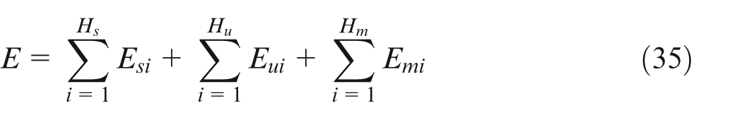
The author’s research group has already proposed a method for forecasting the energy consumption of machine tools during the service process, which needs to evaluate the start-up energy consumption as equation (35). 11 Therefore, the methods presented in this article are helpful for predicting the whole energy of the machine accurately. For example, start-up energy consumption calculated by equation (11) or (12) can be substituted directly into equation (35) to obtain the whole energy consumption E of the machine tools. H represents the number of the sub-process during the service process and i is the serial number. s, u and m are labelled as the start-up process, no-load process and machining process, respectively
This method was applied to forecast the energy consumption for vertical machining centre PL700 under the operation. The parameters of PL700 are shown in Table 2. The

Parameters for PL700 vertical machining centre, the cutter and the part.
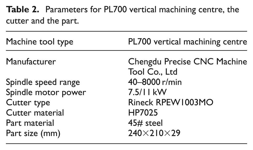
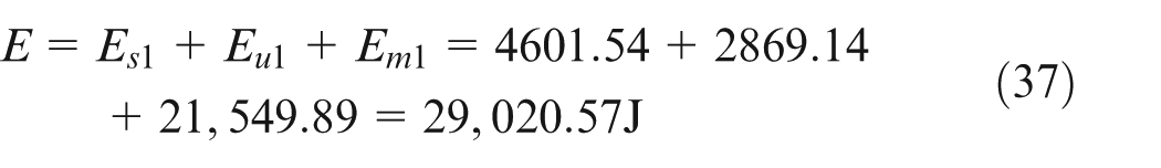
The parameters chosen were spindle speed 3600 r/min, depth of cut 0.15 mm, width of cut 5 mm and feed rate 576 mm/min to mill the steel plate along a straight line. The information about the cutter and the steel plate is shown in Table 2. This milling process has only one start-up process, one no-load process and one milling process. The time durations for those processes are 500, 4450 and 28,800 ms, respectively. Energy consumption for the start-up process according to equation (37) is 4601.54 J. The no-load power at this spindle speed in the energy database that has been established by the author’s research team is 644.75 W, which means that the energy consumption for this no-load process is 2869.14 J. Likewise, the milling power is 748.26 W obtained by cutting the force multiplying the cutting speed, and the energy consumption for this process is 21,549.89 J. Thus, the forecasting energy consumption is
In this forecasting procedure, the start-up energy consumption is calculated using a start-up energy database. At the same time, the no-load power and milling power are also retrieved from the existing energy database. After a simple mathematical calculation, the whole energy consumption of a piece of work becomes explicit. When using this procedure to forecast machining energy consumption for a batch of work pieces or a large number of pieces, the results will support the planning of the energy consumption quota in a manufacturing system.
Conclusion
This article proposes a method for acquiring start-up energy consumption before machining. For a certain machine tool, the start-up time and its energy consumption are affected only by its spindle speed. When the machine tool is in operation, the feature of the power curve for the start-up process is quite different from others. With this characteristic, the changing rate of the power value is used to identify the start-up process. When the changing rate overwhelmingly surpasses a selected starting boundary, the start-up process begins. Likewise, when the rate is constantly lower than the end boundary, the start-up process ends.
Among 12 tested machine tools, the use of two types of database is suggested to save information for SSR machines and SLSR machines. For SSR machine tools, the spindle speeds shift intermittently. For this reason, discrete data tables are adequate to save both the time duration and the energy consumption for the start-up process. Comparatively, the spindle speeds for SLSR machine tools can shift continuously from one speed to another. The time duration and energy consumption for those machines are then recommended to be saved by quadratic functions. Coefficients in those functions can easily be acquired by mathematical fitting methods on the power values. This article also provides a three-fragment function to fit the power curve at a certain spindle speed. Energy consumption from the beginning of the start-up process to any time within this process can easily be calculated by this function.
This method was experimentally validated and shown to be conveniently applied to experiments on two types of machine tools. In addition, the application case study shows that this method is practical to forecast energy consumption of the machining process and to help plan the energy quota for manufacturing systems.
Further work will be performed to apply this method to obtain the start-up energy consumption of different types of machine tools and eventually to establish a fundamental energy consumption database that is useful for the prediction, quota planning, management and saving of energy in machining processes.
Footnotes
Appendix 1
Declaration of conflicting interests
The author(s) declared no potential conflicts of interest with respect to the research, authorship and/or publication of this article.
Funding
This work is funded by the National Natural Science Foundation of China (Grant No. 51375513) and the National Hi-Tech R&D Program (863; Grant No. 2012AA041306).