
Abstract
Incremental forming is a method for rapid-prototyping and low-volume production. Incremental sheet metal hammering is relatively a new technique in which successive blows of punch on the clamped sheet are used to apply desired shape. In this article an incremental sheet metal hammering system has been designed and developed. The developed mechanism is equipped with a cam shaft including some hard metallic balls as dampers into the central driver core. It can reduce the system vibration to some degree. This research describes the theoretical, simulation and practical background of the designed system. In addition, experiments are accomplished to assess the tool performance. Also, by evaluation of experimental results, the effects of some parameters on the surface quality and maximum forming angle have been studied.
Introduction
By increasing demand of low-volume production, incremental sheet metal forming (ISMF) is considered due to the use of simple die for the forming process. This process is based on applying the rotational punch on the clamped sheet incrementally. Due to the flexibility of numerical control machines, use of this machine is very common for the process of incremental forming. For example, Ambrogio et al. 1 made a medical product using a computer numerical control (CNC) machine and achieved desired shape by incremental forming method. Hirt et al. 2 showed the feasibility of ISMF process for producing of complex shape by CNC machine and simple die. Henrard 3 used a three-axis CNC machine to form a part in the speed of 2000 mm/min by a horizontal spindle. Some researchers utilized specific systems of incremental forming which are as follows: Allwood et al. 4 designed and manufactured a novel incremental forming machine that is complemented with sensors to measure the force and the final shape. Jeswiet et al. 5 presented the ISMF state of the art for symmetric samples. In this review article, they tried to point out the forming parameters such as spindle speed, formability, surface roughness, forming forces and tool path generation. Xu et al. 6 studied the effect of tool rotation and laser surface texturing (LST) on formability in single-point incremental forming. They analyzed different roles of friction and heat during the forming process on sheet formability, forming forces and temperature. Lu et al. 7 pointed out the friction effect on single-point incremental forming using a roller-ball tool. Cui et al. 8 presented the electromagnetic incremental forming as a novel aluminum alloy sheet and tube forming technology. Yang et al. 9 presented the dieless incremental hole-flanging of thin-walled tube for producing branched tubing. They studied the force and deformation behavior along with the defects in the process using experiment and numerical simulations.
In recent years, the incremental sheet metal hammering (ISMH) as a development of ISMF process has been introduced. To achieve the ISMH process, the rotational movement of punch in ISMF should be changed to the sequence vertical motion. In fact, the ISMH process is based on movement of successive blows of punch (without any rotation) in the certain path on clamped sheet. The overall performance of the method is shown in Figure 1. As seen in this figure, the sequence movement of punch in the vertical direction on the movable clamped sheet leads to final shape without friction force between the punch and sheet. Mori et al. 10 presented an ISMH process based on hydraulic mechanism and used a genetic algorithm to determine sequence hammering. Also, Mori et al. 11 presented automation of incremental hammering based on charge-coupled device (CCD) camera. They have studied the surface roughness and quality of formed sheet too. Saotome and Okamoto 12 designed and manufactured an ISMH system using piezoelectric mechanism for micro-forming process. They have presented the performance of micro-forming system by forming 10-μm-thick aluminum foil and utilizing mico-die. Schafer and Schraft 13 presented several mechanism of hammering process and conducted experiments using an industrial robot. In their study, the advantages of this approach and geometric error caused during forming process are discussed. Tanaka et al. 14 have presented a method of error debugging by introducing an impact making tool with servo-motor along with its modeling. They presented an ISMH tool with an end speed of 5 m/s and maximum frequency of 16 Hz. Puzik 15 has designed and made several impacting devices according to associated difficulties. Luo et al. 16 presented a new system of impact incremental forming in which they present both modeling and simulation. Furthermore, Luo et al. 17 completed their studies by manufacturing of hammering machine based on hydraulic mechanism in which they ended up comparing results of theoretical with experimental studies. Bleicher et al. 18 introduced a new mechanism of hammering method based on magnetic tool. They have also studied residual stress and surface quality of the formed sample.
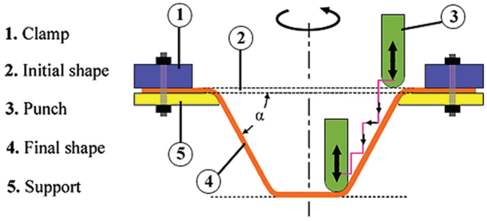
Schematic of incremental sheet metal hammering process.
In this article, an ISMH system based on mass damper has been designed and developed. The theoretical and simulation methods have been used for the prediction of damping. Then, to assess the tool performance, some experiments such as surface quality and maximum forming angle are accomplished.
Design and manufacturing of ISMH system
There are two different approaches to design any new ISMH process: energy approach and fixed displacement approach. But according to the literature review, only one approach is considered, while in this new research idea, both of them have been used. In this section, first the overall performance of the new system is presented. Then, the dynamics of the mechanism have been derived analytically and experimentally. Finally, the features and characteristics of the manufactured mechanism have been studied.
System performance
Figure 2 shows a schematic of designed tool and the layout of three moving balls at three stages: (a) before impact, (b) exactly after impact and (c) after impact. Due to the rotation of central square shaft with angular velocity ω, grooved cam also rotates by the same angular velocity and power transition from rotational state to the directional state is occurred. Since the centrifugal force is applied on the balls, metallic balls are located at the end of the slot due to the rotation of grooved cam. It is shown in Figure 2. At the moment of hammering process, the impact is transferred to the cam and then to the balls. Thus, balls are moved within the grooves by the assumptions of linear momentum. This issue leads to decrease in the system vibration. Finally, balls tend to return to their initial position due to centrifugal force by the rotation of cam.
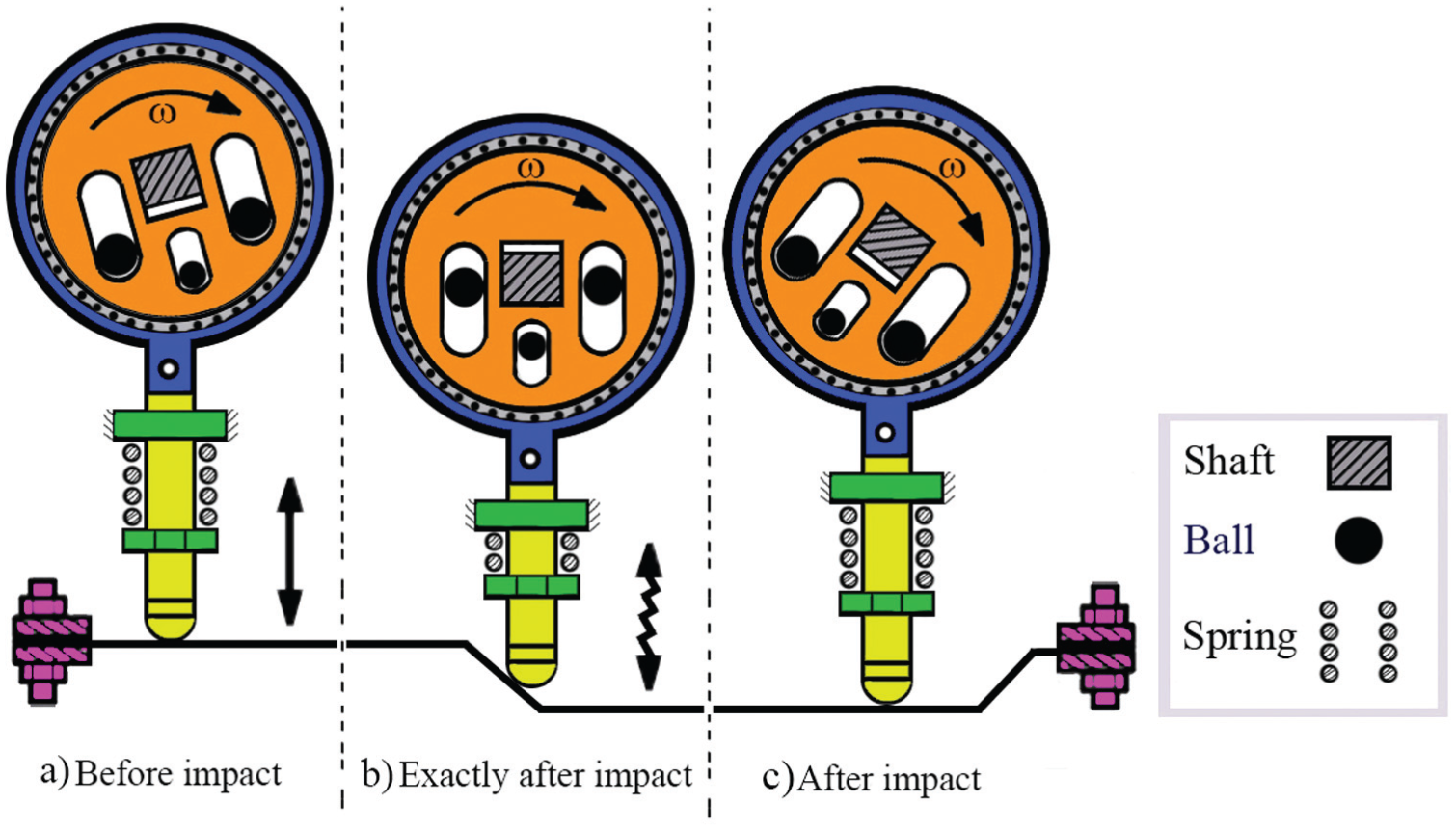
Schematic of new mechanism of ISMH process in three steps.
Dynamic governing equations
To investigate the dynamical equations, development of initial simple model of mechanism is needed. This model illustrates the grooves and the moving balls (Figure 3). The ultimate position of the balls and upward displacement of gap have been shown by dashed lines.
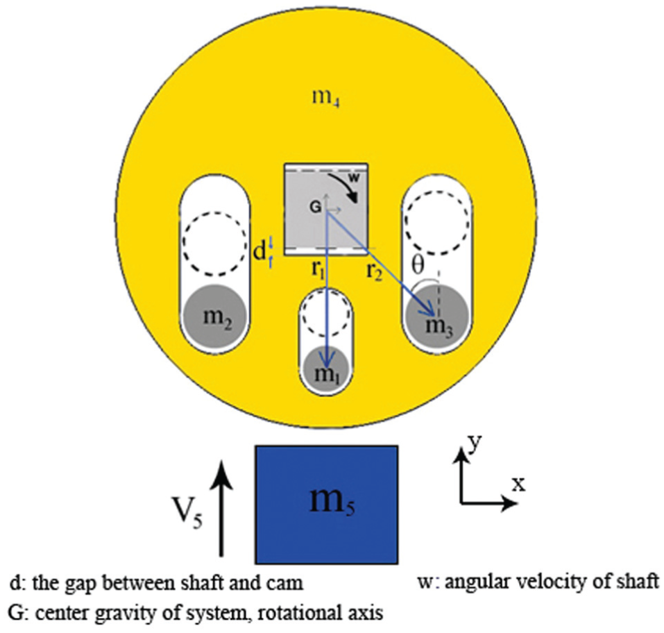
Simple dynamical model of mechanism.
Assumptions which are used to simulate the mechanism are as follows:
Friction force in all parts of system is negligible.
Conservation of energy at time interval between applied impact and bopping cam to shaft is valid.
According to these steps, dynamical analysis of suggested mechanism can be categorized in two stages:
First stage: all parts of system were evaluated at a moment just before the applied impact.
Second stage: the system was investigated at a moment exactly after the applied impact.
According to conservation of linear momentum, these equations can be derived
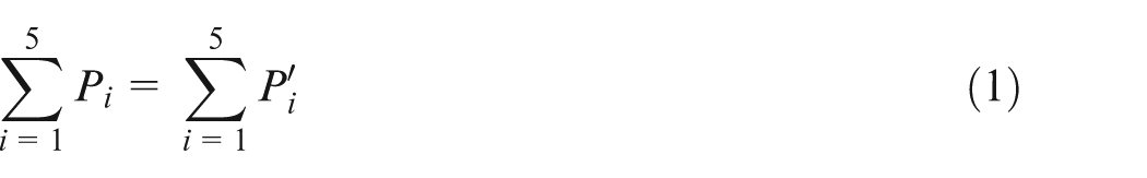
In this equation,
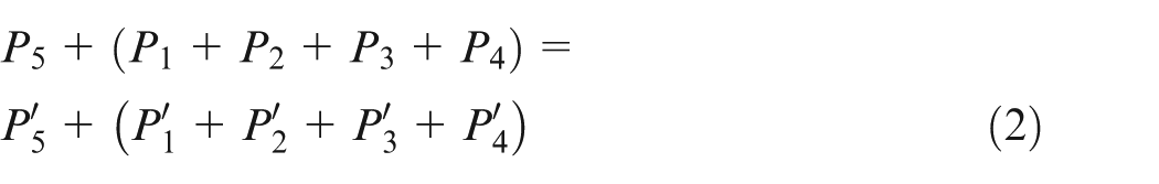
where P1 to P3 are metallic balls’ momentums, P4 is cam momentum and P5 is sheet momentum.
And for initial velocity of parts
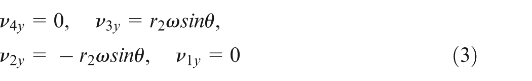
where ν4y, ν3y,ν2y and ν1y are the velocity parts with masses of m4, m3, m2 and m1, respectively.
Since at initial point of process, momentum has two components with opposite orientation, ν3y and ν2y, their effect on each other is neutralized, and momentum value of cam and its components becomes zero. By assuming that at a moment just after impact the velocity of cam and its components is equal, equation (4) can be presented

Since the velocity is constant and m2 = m3, equation (5) can be developed as follows

where ν5 is the punch velocity. The velocity ν′5 is unknown. So, using the restitution coefficient (CR) is necessary
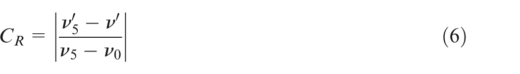
where ν0 is the total velocity of cam and balls, which is equal to zero at initial time. As a result
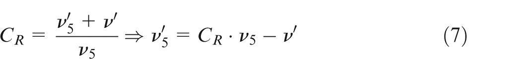
By substituting equation (7) into equation (5), initial velocity of cam just after applied impact, ν′, can be computed
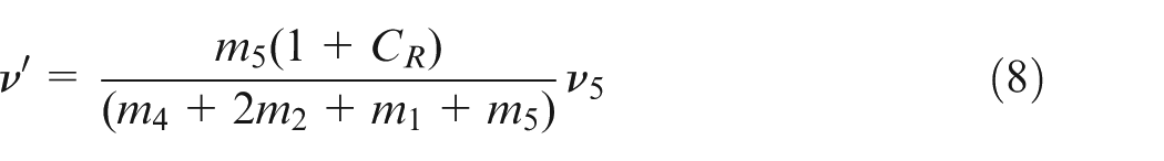
Finally, to calculate the amount of transferred momentum to the shaft, mass of the cam is multiplied by its velocity at a moment of hitting the shaft.
Dynamical simulation of the process
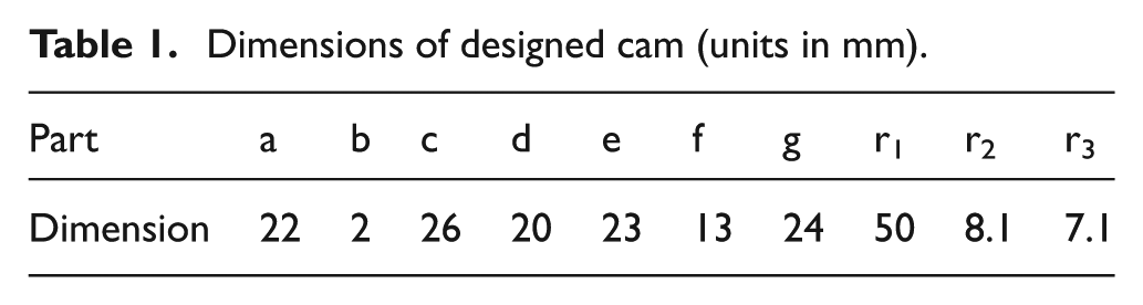
To simulate the mechanism of the system, the Working-Model four-dimensional (4D) dynamical simulation software has been used. The designed assembly and its dimensions have been shown in Figure 4 and Table 1.
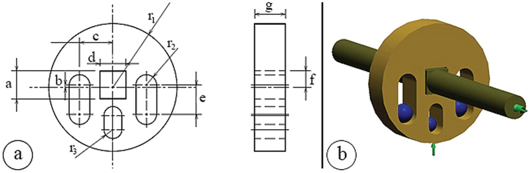
The views of designed system: (a) dimensions and geometrical parameter and (b) 3D image and boundary conditions.
Dimensions of designed cam (units in mm).
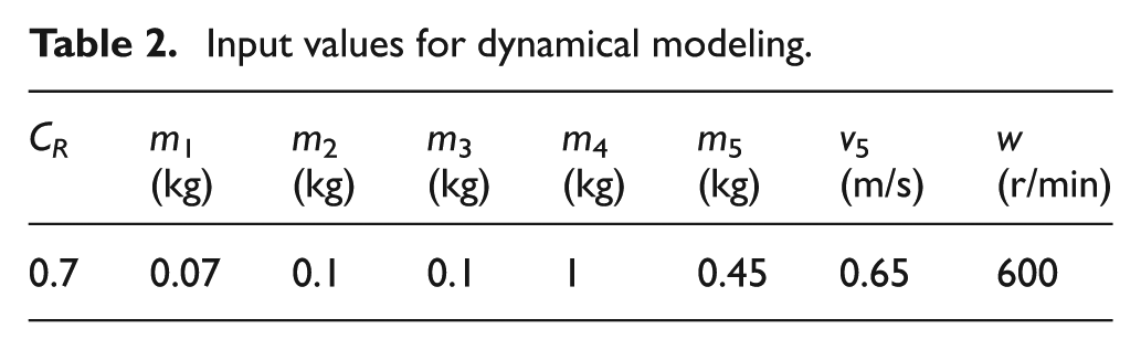
The mechanism is based on changing rotational motion to linear motion. As the punch is so rigid, total impact will be transferred to the central core. According to the input values (Table 2), dynamical modeling is done and the results are evaluated.
Input values for dynamical modeling.
Features and characteristic of manufactured tool
The assembled ISMH tool is fixed on a milling machine main head and machine table applies the feed rate. The frequency required for the forming process can be selected by adjusting the angular velocity of the machine spindle. The punch head with several diameters can be considered by using the screw mechanism. Different views of manufactured hammering system have been shown in Figure 5. This mechanism has several features which are as follows:
Total mass: 8.9 kg
Frequency amplitude: 4 mm
Punch radius: adjustable
Maximum frequency of impact: 25 Hz
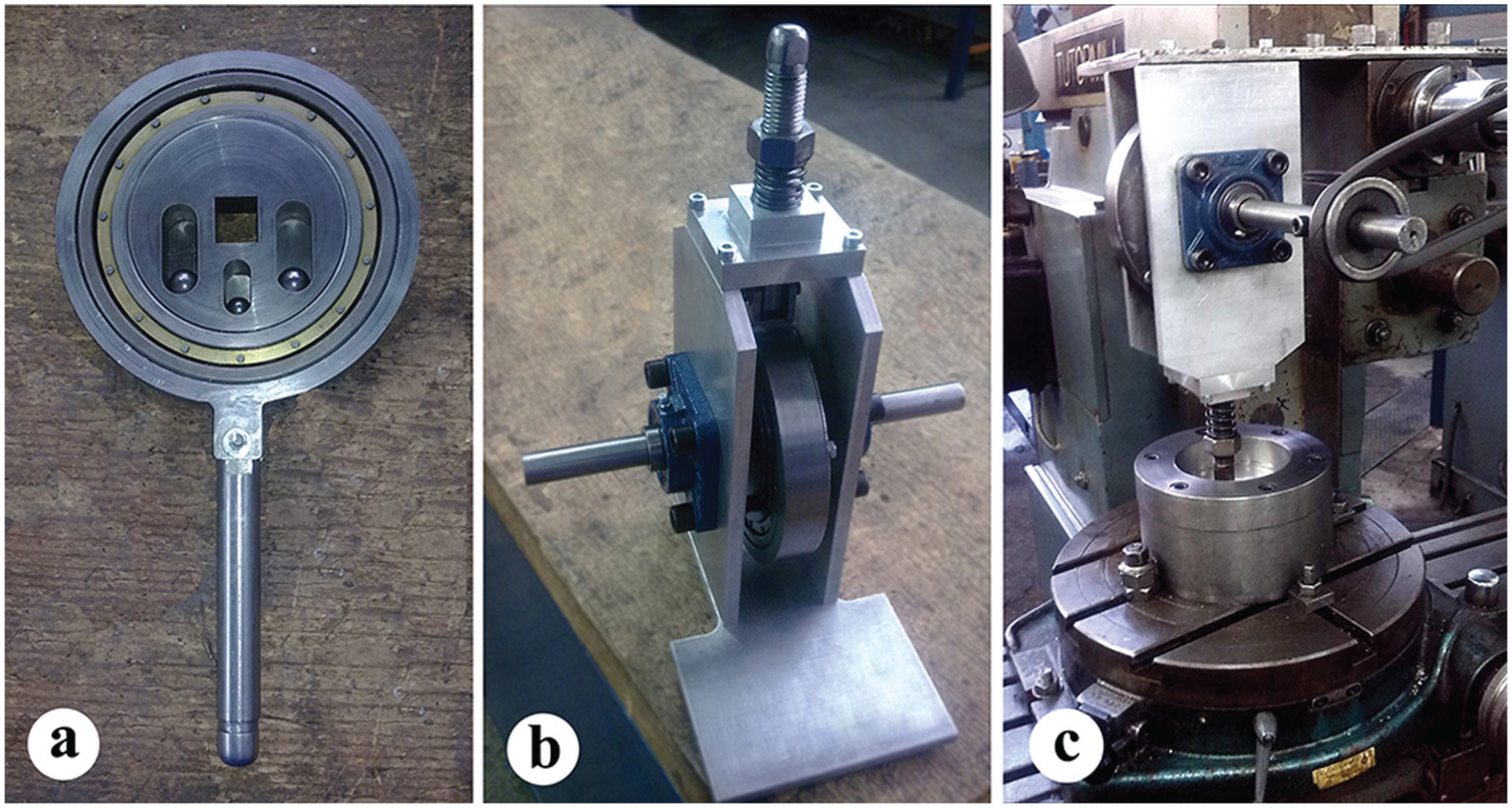
New incremental hammering tool: (a) central mechanism, (b) hammering tool in upside-down position, and (c) overall view of connecting to the milling and die.
Experimental study
In this section, the effects of two manufacturing parameters have been investigated experimentally. The first one is evaluation of surface quality versus tool diameter. The second study is related to the effect of punch diameter and frequency on the maximum obtainable cone angle before failure. In order to assess these issues, circular blank made from AA 1100-O sheet was fully clamped and then was formed incrementally by hammering tool. Finally, the experimental results were analyzed.
Assessment of surface quality
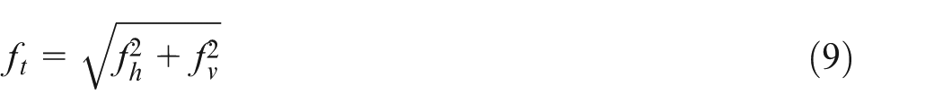
Surface roughness after forming is correlated to several parameters such as the punch diameter and its feed rate. After forming process, the specimens were cut in radial direction and then roughness test was carried out. For geometrical study of hitting condition in this process, a simple model is shown in Figure 6. According to relation (9), the total feed on the sheet surface is related to the feed in the vertical and horizontal directions. By studying the geometrical shape, the roughness caused by successive blows of punch with radius of
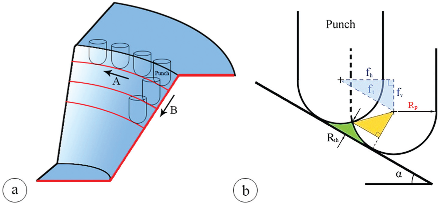
Schematic of the surface roughness: (a) forming strategy and (b) geometrical study.
According to Figure 6, forming strategy is divided into two general steps A and B. In the conventional ISMF, the punch was moved in path A continuously and in path B discretely. But in the ISMH process, discretization movement was observed for both A and B paths. Due to the high frequency of punch in ISMH process, the discretization effects can be neglected for path A and we will have
Also
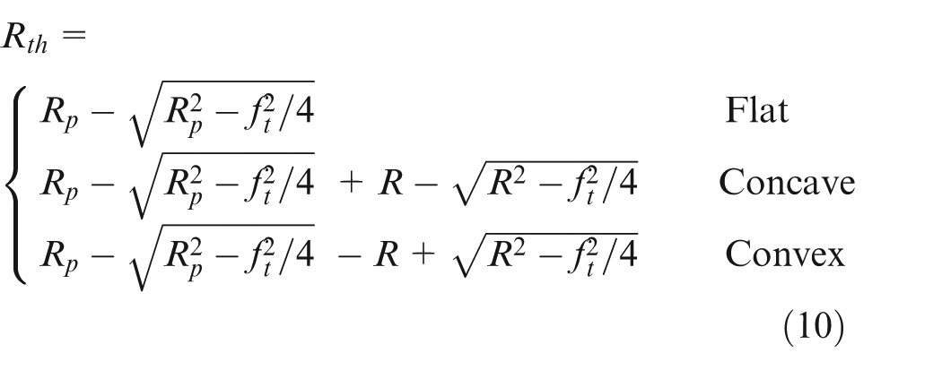
By assuming a constant feed, when the diameter of punch increases the roughness value will be decreased due to lower overlap.
Results and discussion
In this section, first, the results of analytical and dynamical modeling are presented and compared. Then, the result of experiments such as surface quality and maximum obtainable cone angle is discussed.
Results of analytical solution and dynamical modeling
In order to assess the effect of mass dampers on the reduction of vibration, variation of velocity in the central core (cam) with the presence of mass damper is required. Dynamical simulations for evaluation of mass damper effect are shown in Figure 7.
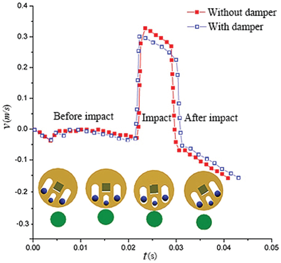
Change in the velocity using mass damper.
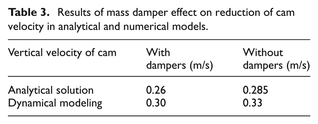
According to Figure 7, at first, the rotational central core has a velocity approximately equal to zero in the vertical direction. After punch impact on the sheet, the velocity of the cam changed suddenly and then returned to its initial state after a full period. As shown in Figure 7, the velocity of the cam is increased in without damper case. The validation is presented in Table 3 showing a difference of about 15% between dynamical modeling and analytical solution results. As given in Table 3, comparison of the vertical velocity of the cam in cases of with and without damper shows that some vibration of mechanism was removed (about 9%) by using mass dampers.
Results of mass damper effect on reduction of cam velocity in analytical and numerical models.
Surface quality
The value of roughness for the initial shape is 1.04 μm. The surface roughness variation was obtained by using punches with different diameters. The results are demonstrated in Figure 8. These values include surface roughness of the inside and outside of formed sheet.
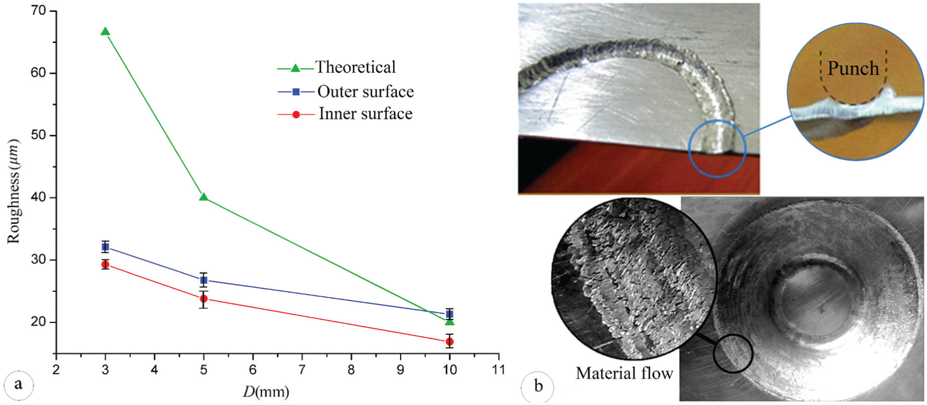
The results of surface roughness for frequency of 25 Hz: (a) measured by roughness tester and (b) material flow in the vicinity of punched areas (small punch diameter).
According to this figure, by increasing the punch diameter, roughness value decreases and leads to improvement in the finish surface. In fact, the surface quality was increased about 43% by increasing punch diameter from 3 to 10 mm. By increasing punch diameter, theoretical values have a better validation with experimental results. In the small punch diameter, higher material flow in the vicinity of punched areas was observed due to the penetration of punch into the sheet (for high-frequency impact). It is shown in Figure 8(b). Existence of these material flow is the reason for higher roughness on the surface and creation of the problem in control of roughness for small punch diameter.
Assessment of maximum cone angle
According to the ISMH process, successive blows of punch were applied to the aluminum clamped sheet and forming process of the cone was started with constant angle. The forming process will be stopped by observation of first crack or local tearing in the sample. The cone height was recorded in certain punch diameter and cone angle. In this experiment, AA 1100-O sheet with initial thickness t equal to 0.5 mm was used. Failures are shown in Figure 9 for some of the samples at different punch diameter and different cone angles.
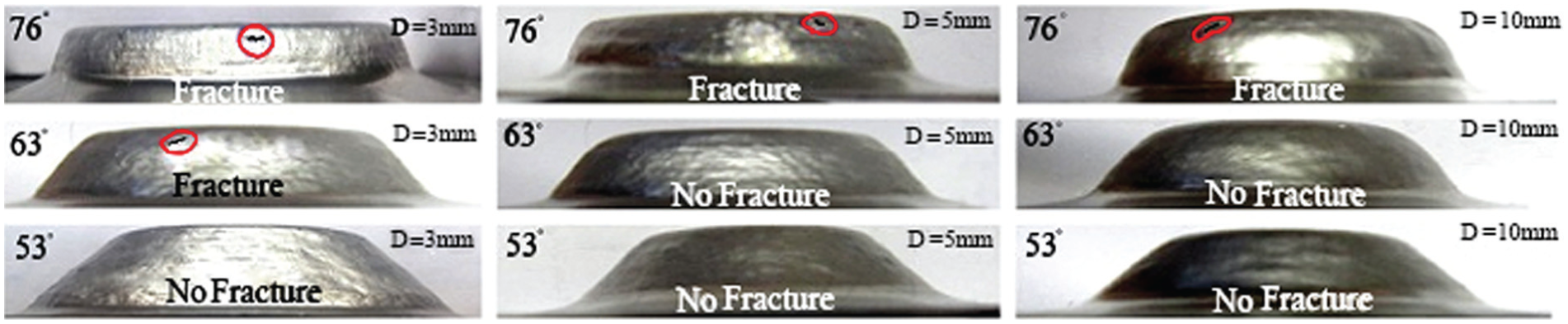
Several samples of aluminum sheet after forming process.
The height of the cone after the failure is recorded to consider cone angle effect. The results are shown in Figure 10.
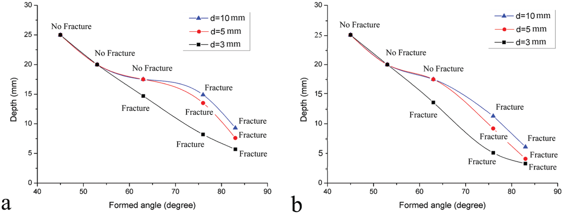
Maximum forming angle versus height: (a) punch-frequency f = 13 Hz and (b) punch-frequency f = 25 Hz.
According to this figure, height of cone is reduced by increasing the forming angle. Also, by increasing frequency of punch, probability of failure in the formed sheet is increased. This factor constrains the cone angle with a certain height. Reducing the punch diameter leads to generation and propagation of cracks in regions with lower height. For assessment and comparing the effect of parameters, first one parameter is assumed to be constant and then the influence of other parameters is studied. So, at an angle of 77° and a frequency of 13 Hz, maximum forming height is improved about 56% by increasing punch diameter from 3 to 10 mm.
Conclusion
In this article, design and development of ISMH-based system on mass damper has been presented. For evaluation of the damping mechanism, the analytical method and dynamical modeling were used. Then, by some experiments, the effects of tool parameters on the surface quality and maximum forming angle have been studied. Considering the points discussed and analyzed, the following could be concluded:
Vibration of mechanism was removed to some extent (about 9%) by using mass dampers.
By using simple design for hammering tool, total mass was decreased (8.9 kg).
The surface roughness value was reduced by increasing punch diameter and decreasing feed rate. Also, for punch with diameter more than 7.5 mm, a good accordance between theoretical and experimental results was observed.
The maximum forming angle and height were reduced and limited by increasing punch-frequency and decreasing the punch diameter.
By increasing punch diameter from 3 to 10 mm (about 230%), the formability was increased (about 56%).
Footnotes
Declaration of conflicting interests
The author(s) declared no potential conflicts of interest with respect to the research, authorship and/or publication of this article.
Funding
The author(s) received no financial support for the research, authorship and/or publication of this article.