
Abstract
This study was performed to investigate the effect of welding sequence on fillet welding distortion. It proposes a new model of joint rigidity method, which can determine the welding sequence for minimum welding distortion, through a reliability validation done via experiments and welding distortion analysis using the equivalent load method. A new joint rigidity method considers the gap between base plate and stiffener and the fillet welding sequence at left/right bead. Fillet welding sequence at left/right bead could be considered by setting welding beads at left/right as a separate solid element after welding sequence was drawn by new joint rigidity method. Analysis and experiment for welding distortion for the test specimen with different stiffener distances were conducted. It was confirmed that the experimental and analysis results were well-matched. The validity of welding sequence using joint rigidity method was followed after the comparison of the welding distortion for the small components for ship building. Note that the welding sequence by which welding distortion became maximum and minimum was drawn using joint rigidity method for the small assembly components. Welding distortion was also analyzed using equivalent load method. Analysis results revealed that the maximum welding distortion less than 10 mm was generated. Welding distortion less than around 5 mm occurred in welding sequence which minimized welding distortion compared with welding sequence, generating maximum welding distortion.
Keywords
Introduction
Heat stress occurs near weld zone due to uneven temperature distribution by welding and it leads to welding residual stress and welding distortion. Welding distortion 1 not only changes the shape or decreases the structure strength but also becomes a major factor of decreasing productivity. In recent years, the automation of welding process 2 has actively progressed to improve productivity. However, in case of robot welding used in the automation, it does not have a perfect visual sensor as humans do. The result is that if welding distortion occurs, it cannot sense by itself so that either welding defects are generated or workers for robot operation have to provide information about welding location per stage directly to the robot. Therefore, accurate prediction and minimization of welding distortion are mandatory for the automation of welding.
Thermal elastic–plastic analysis,3–7 inherent distortion method,8–10 and equivalent load method 11 are adopted as methods to predict welding distortion. Since these methods have merits as well as drawbacks, an analysis method can be appropriately chosen so that reliable results can be obtained depending on the analysis structures. However, although these predication methods for welding distortion can estimate welding distortion generated during welding, it cannot decide welding sequence which can minimize welding distortion. Therefore, it is necessary to pursue researches to draw welding sequence by which welding distortion can be minimized and to predict welding distortion by drawing a welding sequence.
Welding distortion is affected by not only welding speed, plate thickness, implemented current and voltage, and restraint of welding structures but also welding sequence. 12 The preheating is one of the useful methods to control the welding distortion. 13 It was found that the differential preheating control is effective in adjusting the welding-induced twist distortions using finite element analysis. We have performed research about the effect of welding sequence on the welding distortion among various factors affecting welding distortion. For the initial researches stage of welding sequence, research about the effect of stiffness of panel and length of stiffener on the fillet welding using restraint coefficient for angular distortion was performed.14,15 After that, research was conducted about both-side welding and single-side welding, welding jig, and arbitrary welding sequence for large-sized thin plate panel structure.16–18 A three-dimensional (3D) finite element approach based on commercial code was developed to investigate the effect of welding sequence on welding residual stress distribution in a thin-walled aluminum alloy structure 19 and in T-joint welded structure. 20 Selecting a suitable welding sequence can reduce the final residual stress and leads to high-performance, low-distortion assemblies which can ultimately be manufactured at the lowest possible cost. Another approach was to use the welding sequence optimization connecting with commercial code in order to maintain the original geometry. The sequence in which a part is welded has a significant effect on the distortion of the part as the stiffness changes significantly depending on which welds have already been executed. To investigate the significance of this effect, a second Hyper Study optimization 21 was set up to optimize the sequence of welding to give minimal distortion of the tower. This method greatly reduced the computational expense needed in weld planning, without significant loss of accuracy. A research to control welding distortion using welding sequence was started by drawing and deciding welding sequence from a stiffness of weld joint using joint rigidity method.22,23 This method was applied to prevent welding buckling for aluminum thin plate. Joint rigidity method is a method to minimize welding distortion after calculating stiffness by loading unit moment on the weld joint and by welding the part with substantial stiffness. However, there has been no research wherein welding sequence was drawn and applied for steel structures such as ships.
In this study, a new joint rigidity method model is proposed to consider left/right welding sequence by supplementing existing joint rigidity method and this model was validated by welding distortion analysis using equivalent load method. First of all, welding sequence was drawn using joint rigidity method for the three types of weld structure having different stiffnesses’ space in weld joint in order to validate the decided welding sequence. After that, this welding sequence was analyzed through experiment and equivalent load method to investigate the effect of welding sequence on the welding distortion. In addition, the effect of welding sequence on the welding distortion was reviewed by conducting analysis using equivalent load method for the ship’s small component fabrication with validated joint rigidity method.
Modeling of joint rigidity method and equivalent load method
Modeling of joint rigidity method
The magnitude of welding distortion occurred differently depending on the restraint at weld joint. 15 Therefore, there is need to decide adequate welding sequence to minimize fillet welding distortion (Figure 1(a)) according to the restraint of welding joint. Welding sequence is decided by calculating all the relative restraints at weld joints comparing angle distortion generated by loading unit moment on the fillet weld joint and it is called “joint rigidity method.”22,23 The existing joint rigidity method (Figure 1(b)) applies unit moment at welding joint connecting base and stiffener using shell element. Thus, the existing joint rigidity method could not be considered for the gap between base and stiffener, the effect of temporary welding (tack welding), and left/right welding sequence of fillet welding. In order to consider these problems, new joint rigidity method has modeled shell element for flange and stiffener and solid element for welding bead in Figure 1(c). At this time, the distance between flange, the length of tack welding and stiffener, and the size of solid element were obtained from the experimental conditions. Also, solid element was generated at weld joint after welding to consider the effect of left/right welding sequence of fillet welding. Unit moment was loaded at joint no. 3 as an arrow in Figure 1(c), and the angular distortion generated from it was divided by maximum angular distortion generated on unit moment to calculate relative stiffness. If welding is executed in the order of larger stiffness using drawn relative stiffness, the welding distortion according to the welding sequence could be minimized.
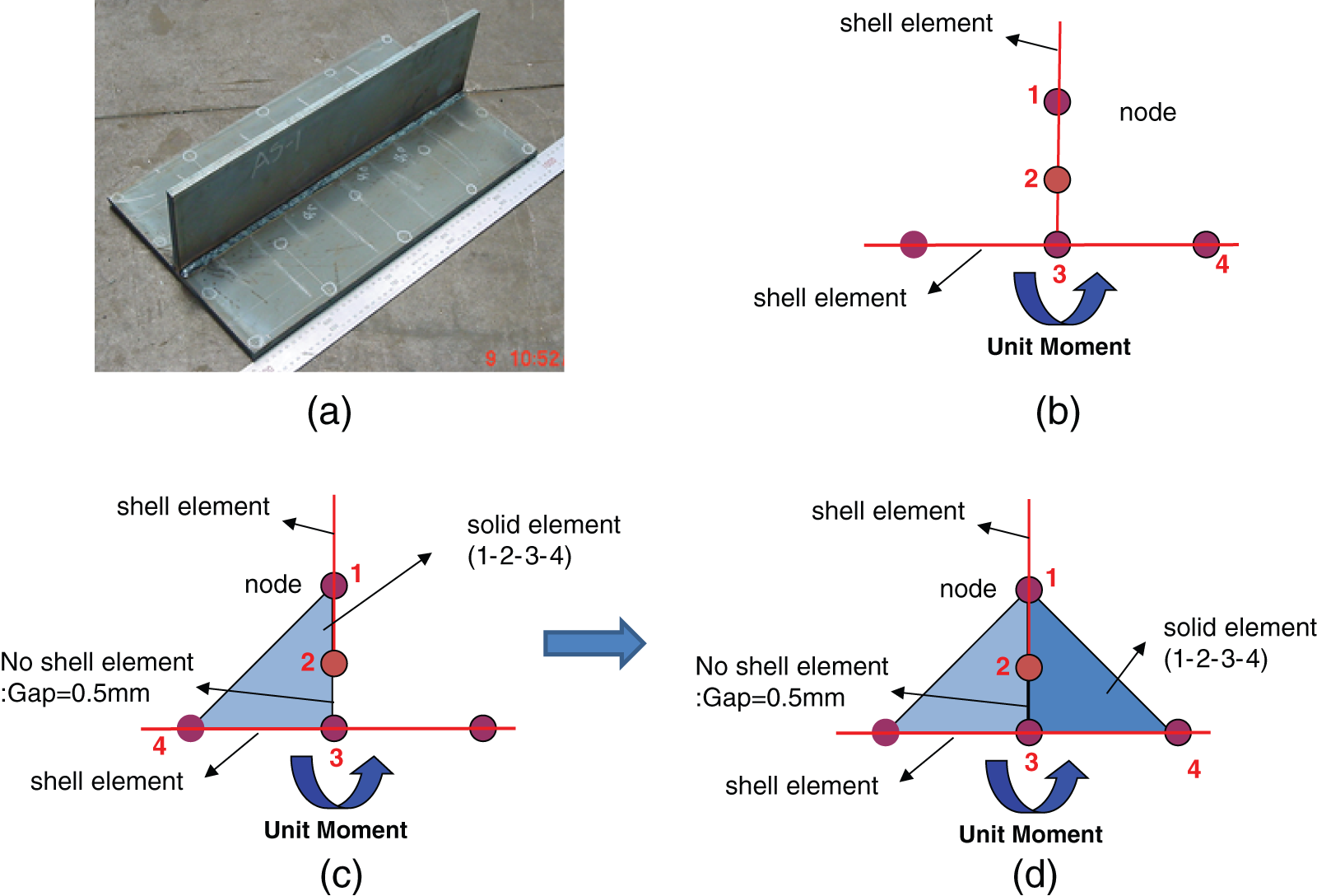
Modeling of joint rigidity method: (a) fillet welding, (b) existing joint rigidity method, and (c) new joint rigidity method.
Modeling of equivalent load method
In case of large-sized structure, huge calculation time and memory in the computer are necessary if welding distortion is calculated using thermal elastic–plastic analysis. Therefore, in this study, equivalent load method which uses welding distortion generated by complicated thermal elastic–plastic behavior by substituting it with equivalent load was used in order to predict the welding distortion of large-sized steel structure. Welding distortion is largely categorized into longitudinal shrinkage, transverse shrinkage, and angular distortion. Welding distortion was predicted by calculating the equivalent load from each welding distortion obtained by the experiment through elastic finite element method (FEM) analysis. During analysis, correlation between equivalent load (PL, PT, and M) and welding distortion (δL, δT, and θ) can be linearly expressed as in equations (1a), (1b), and (1c)
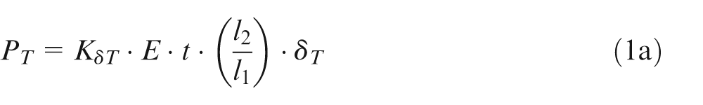
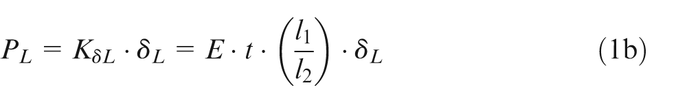
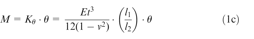
Here, M is the equivalent bending moment (N mm); PL is the equivalent longitudinal load (N) toward weld line direction; PT is the equivalent transverse load (N) toward the vertical direction of weld line; KδT, KδL, and Kθ are the longitudinal stiffness (N/mm) toward tangent line, transverse stiffness (N/mm), and bending stiffness (N mm), respectively; E is the Young’s modulus(N/mm2), t is the thickness; v is the Poisson’s ratio; δL is the longitudinal shrinkage (mm) toward weld line; δT is the transverse shrinkage toward vertical direction of weld line (mm); θ is the angular distortion (rad); l1 is the longitudinal element length (mm) toward weld line; and l2 is the transverse element length (mm) toward vertical direction of weld line.
Figure 2 shows a mechanical model on which equivalent load which causes welding distortion during fillet welding is applied. The equivalent load obtained using equation (1) was used as load as shown in Figure 2(b) and elastic FEM was carried out. At this time, longitudinal element length l2 is the length till end of heat-affected zone at both sides and equivalent load and moment were loaded at the end nodal point. Equivalent load toward weld line direction was loaded at the point distanced as much as l2 from intersection point of flange and stiffener.
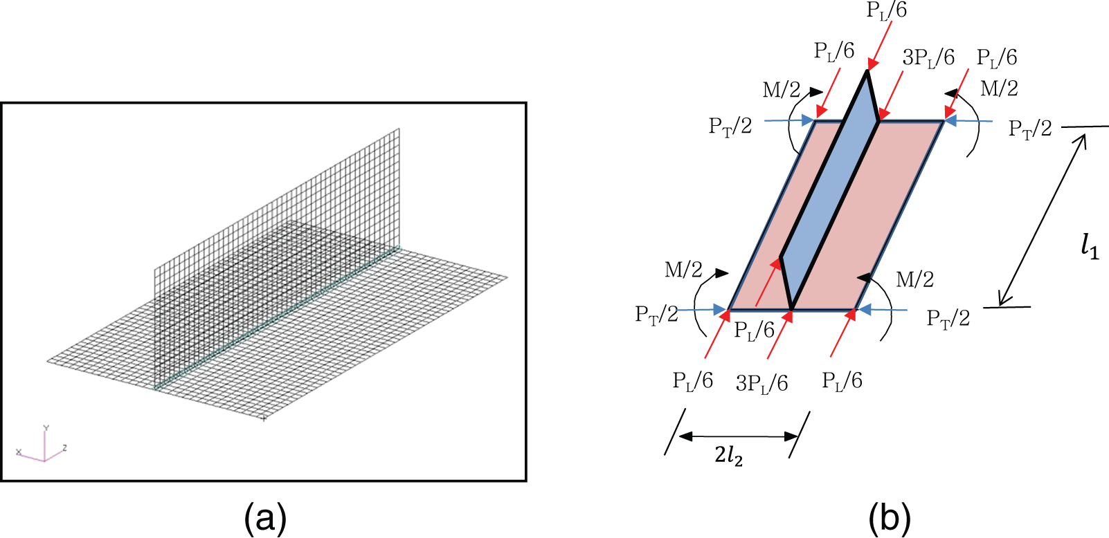
Mechanical model of equivalent loads: (a) model of fillet and (b) modeling of equivalent load.
Validation of joint rigidity method
Welding sequence by joint rigidity method
Figure 3 shows the decision of welding sequence by joint rigidity method and shape and size of analysis model to validate the welding sequence. The total number of analysis models was three. The model was categorized into distance between stiffeners; that is, 400 mm (WS400), 800 mm (WS800), and 1500 mm (WS1500). The thickness of stiffener was 12 mm and the thickness of flange was 15 mm. The steel material used in the experiment was mild steel having a yield stress (σy) of 400 MPa, Young’s modulus of 219 GPa, and Poisson’s ratio of 0.3. The welding length of all the models was 500 mm and the throat thickness during fillet welding was 5 mm. Temporary welding was carried out at 50 mm from both ends of weld line.
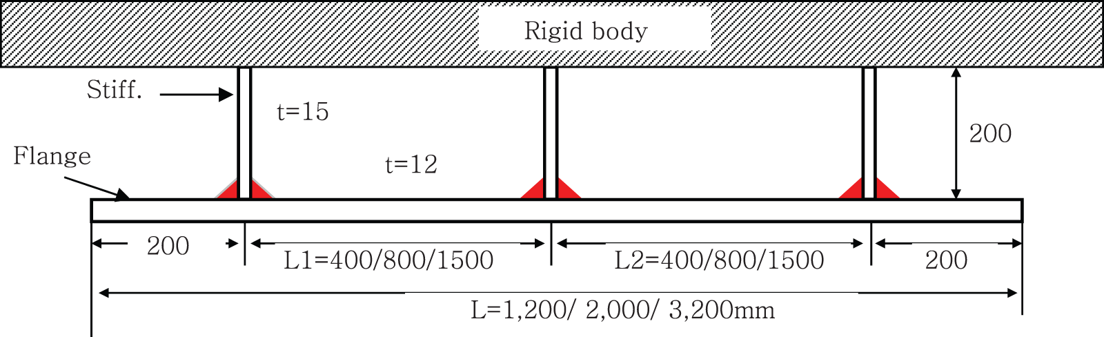
Dimension and shape of specimens.
Figure 4 shows model shape and boundary condition of Model WS400 wherein the gap between mid-stiffeners used in the analysis was 400 mm. Since the upper end of stiffener was welded on the steel body, the boundary was restrained for all. The modeling of weld zone is shown in Figure 1(b). The unit moment to draw welding sequence was implemented at the center of weld joint. Fillet weld bead was assumed as solid element to consider fillet welding sequence, and solid element was made to be generated when welding was completed. Unit moment was loaded as arrow at nodal point 3 in Figure 1(b), while angular distortion generated from here was divided by maximum angular distortion generated at unit moment to calculate relative stiffness. If welding was executed in the order of higher stiffness obtained by unit moment, the distortion could be minimized by stiffness attributed by welding sequence.
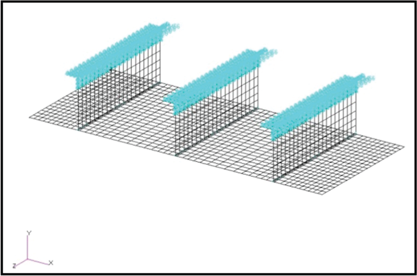
Model of fillet welding for specimen (WS400).
Figure 5 shows a sequence of deciding welding sequence for model WS400 obtained by joint rigidity method. Welding sequence T1 was decided in the order of larger stiffness, while welding sequence T2 was decided in the order of weaker stiffness. First of all, unit moment was loaded as in Figure 1(c) to decide welding sequence. The stiffness of each weld joint was calculated and then stiffness rate was expressed by dividing each stiffness value by maximum value. Once one weld joint was decided according to percentage, the decided weld joint generated solid element. Again, unit moment was loaded on the other weld joint except for the decided weld joint to decide the next weld joint. Welding sequence T1 which was expected to minimize welding distortion was decided in the order of larger stiffness at weld zone. Reversely, welding sequence T2, which was expected to have maximum welding distortion, was decided in the order of less stiffness.
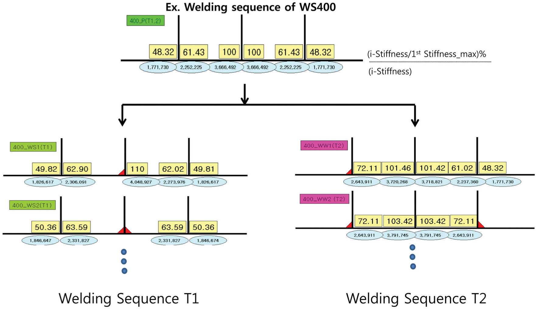
Welding sequence by joint rigidity method (WS400).
Figure 6 shows welding sequence for WS400, WS800, and WS1500 obtained by joint rigidity method. Welding sequence was displayed as the same regardless of the gap between stiffeners. Welding sequence T1 by which welding distortion was expected as small was decided from center until both ends whereas welding sequence T2 was decided as welding done from both ends to center of weld joint.
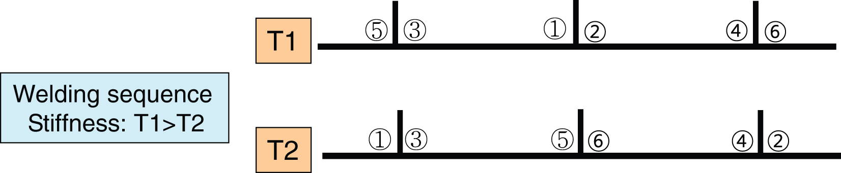
Welding sequence using joint rigidity method (WS400, WS800, and WS1500).
Analysis result by equivalent load and its validation through experiment
Welding distortion analysis was carried out using equivalent load method according to welding sequence obtained by joint rigidity method. The analysis models used were three types of models (WS400, WS800, and WS1500) drawn by joint rigidity method. Welding conditions were 280 A for current, 31.5 V for voltage, 10 mm/s for welding speed, and 3.5 mm for throat thickness during fillet welding. Also, temporary welding was performed at 50 mm from both ends of the weld zone. Fillet welding was executed for all the test specimens under the same welding condition. Vertical transverse shrinkage, horizontal transverse shrinkage, and bending moment were used with equivalent load which was used in equivalent load method. Equivalent load value was obtained by carrying out welding experiment with the same test specimen under the same welding condition. 11 At this time, vertical transverse shrinkage was 151 kN obtained using the equation proposed by Sato 24 while horizontal transverse shrinkage was 0.17 mm/seam for one weld joint. Angular distortion was 0.00877 rad. These values were applied after substituting them as loads using equations (1b) and (1c).
Figure 7 shows welding distortion obtained by equivalent load method for welding sequences T1 and T2. The magnitude of welding distortion was smaller in the welding sequence T1 than that of welding sequence T2 indicating that the deciding method of welding sequence by unit moment was appropriate. The magnitude of welding distortion was larger in WS1500 which had relatively small restraint. Furthermore, the difference of distortion was less in WS400 and WS800 whose restraints were relatively large, while the effect of welding sequence on the distortion was larger in WS1500 wherein restraint was relatively small. Meanwhile, the magnitude of welding distortion at both the end sides in the welding sequence T2 is smaller than in T1. The main reason is that the outside welding joints of weld sequence ① and ② in T2 are welded at first and then the distortion of the inner welding sequence including weld joints ③, ④, ⑤, and ⑥ reduces the distortion of weld joints ① and ②.
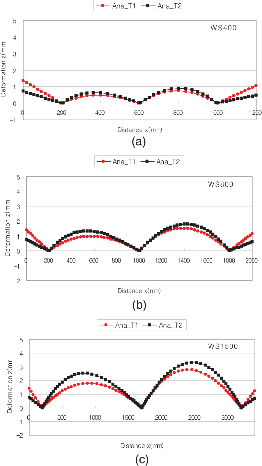
Welding distortion according to welding sequence and stiffener space: (a) WS400, (b) WS800, and (c) WS1500.
The experiment was conducted for the Model WS1500 to validate the analysis results obtained by equivalent load method as in Figure 8. Figure 9 shows the analysis results by equivalent load method and the results obtained through the experiment. The welding distortions were measured by 3D coordinate measuring machine (CMM), which is a device for measuring the physical geometric characteristic of an object and the measurements are defined by electronic touch trigger probe attached to the third moving axis. This machine has portable coordinate and can measure a total of 40 positions per specimen. The experiments were carried out for welding sequences T1 and T2 obtained by joint rigidity method. All the experimental results and analysis results showed that welding distortion was larger with welding sequence T2 than by welding sequence T1. It showed that the analysis results and the experimental results were well-matched.
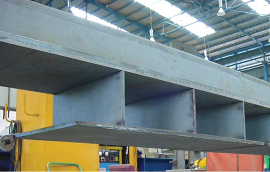
Picture of WS1500 specimen.
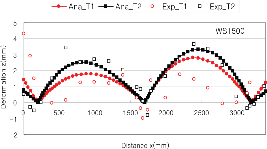
Comparing analysis results and experimental results (WS1500).
Welding distortion analysis for small assembly components
Welding sequence for small assembly components by joint rigidity method
H-type test specimen having general shape among small assembly components was chosen for the experiment. H-type small assembly component was reinforced by reinforcement materials at one side, while fillet welding was laid in length at the other side.
Figure 10 shows the shape and size of H-type test specimen. The specimen was a small assembly component 2000 mm in width and 3000 mm in length with seven fillet welded stiffeners. The thickness of base metal was 15 mm, the thickness of stiffener was 12 mm, and the height set for all was 150 mm. Welding was executed as fillet welding for all under the welding condition of 280 A for current, 31.5 V for voltage, 10 mm/s for welding speed, and 3.5 mm for each throat. The separation distance and welding length for temporary welding were set as 500 and 50 mm, respectively.
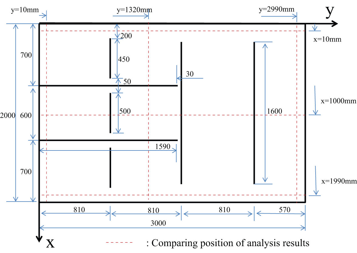
Dimension and figuration of H-type model.
Figure 11 shows the H-type analysis model. For base and stiffener, a shell element having four nodal points was used. For temporary welding and welding beads, a 3D solid element having eight nodal points was used for modeling. The materials for analysis were the same as that in the analysis model as described in section “Welding sequence by joint rigidity method.” Boundary condition was set not to generate rigid body motion. Also, analysis was performed considering the self-weight of the material and its contact with floor.
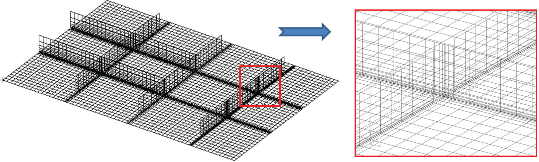
Analysis model of H-type model.
Figure 12 shows bending stiffness obtained by loading unit moment on all the weld joints and welding sequences H_T1 and H_T2 obtained from bending stiffness as the first step. Figure 12(a) shows bending stiffness obtained by loading unit moment on all the weld joints as the first step. Figure 12(b) shows the result of drawing welding sequence in the order of larger bending stiffness as the first step, while Figure 12(c) shows welding sequence drawing result in the order of lower bending stiffness as the first step. Unit moment for welding sequence yields bending stiffness for all the weld joints as shown in Figure 1(c). Once one welding sequence was decided, a solid element was generated on that weld joint. Again, bending stiffness was obtained for the weld joint except for the selected weld joint to decide the next welding sequence. It was confirmed that the first selected welding sequence drawn in the order of larger bending stiffness of H_T1 (Figure 12(b)) had a strong welding stiffness since the surrounding area of weld joint was enclosed by stiffener as shown in Figure 12(a). Also, the first welding sequence H_T2 (Figure 12(c)) selected in the order of lower bending stiffness was the portion where angular distortion was generated since there was no stiffener near weld joint as can be seen in Figure 12(a). Therefore, it was expected that welding distortion occurred less in H_T1 than in H_T2 welding distortion.
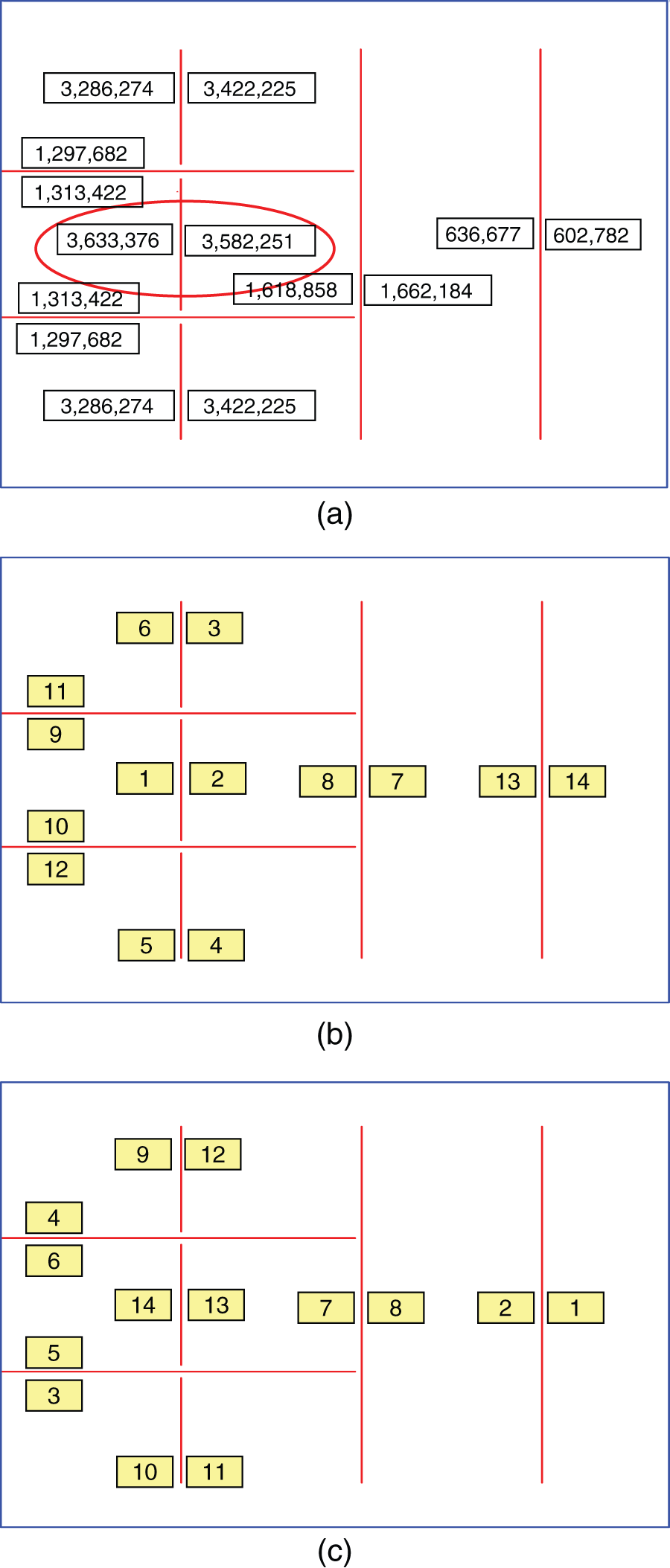
Bending stiffness and welding sequences of H-type model: (a) bending stiffness for welding sequence as the first step, (b) welding sequence to minimize welding distortion H_T1, and (c) welding sequence to maximize welding distortion H_T2.
Results and discussion of welding distortion
Welding distortion analysis was performed by equivalent load method for welding sequences H_T1 and H_T2 obtained by joint rigidity method. Vertical transverse shrinkage, horizontal transverse shrinkage, and bending moment were used as equivalent loads for the equivalent load method. Equivalent load values are the same in section “Analysis result by equivalent load and its validation through experiment” using same the experiment conditions. 11 The model used and the material constants were the same as those used during the analysis of unit moment in section “Analysis result by equivalent load and its validation through experiment.”
Figure 13 shows the location of welding for comparison in the analysis and location and direction of stiffener. From the analysis results, distortion toward z-axis at the locations x = 10, 1000, and 1990 mm along the y-direction and distortion toward z-axis from the points y = 10, 1320, and 2990 mm along the x-direction were compared. Also, the stiffener was fillet welded on the base plate as two numbers toward horizontal direction and five numbers in vertical direction.
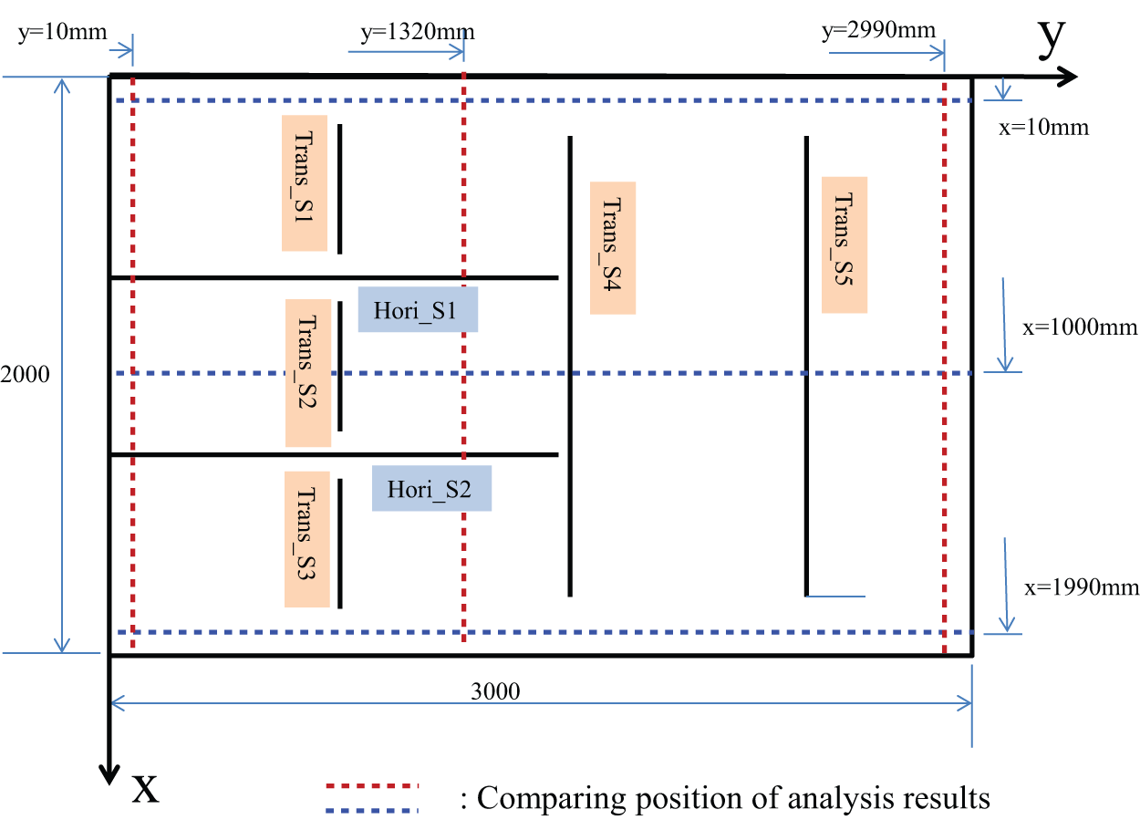
Comparing position of welding distortion and stiffeners’ positions.
Figure 14 shows the development process of welding distortion for H_T1 and H_T2 obtained by equivalent load model. The generation process of welding distortion was after welding sequence 4, after welding sequence 7, after welding sequence 10, and final distortion. The distortion shown in these stages shows combined welding distortion for each step along with welding distortion during the current step as indicated in the legend. The comparison of welding distortion created by welding sequence 4 shows that weld joint by H_T1 was restrained by vertical stiffeners 1–4 (Trans_S 1–4) and horizontal stiffeners 1 and 2 (Hori_S 1 and S 2), resulting in less welding distortion. Meanwhile, distortion by welding sequence 4 of H_T2 did not have stiffener that restrained angular distortion, which resulted in larger welding distortion than that of H_T1. Welding distortion after all the welding was completed sagged toward y-axis direction overall. The reason might be because weld joint in other portions received restraint from the surrounding stiffeners, while weld joint at vertical stiffeners 4 and 5 received relatively less restraint, consequently affecting the angular distortion in weld joints at stiffeners 4 and 5.
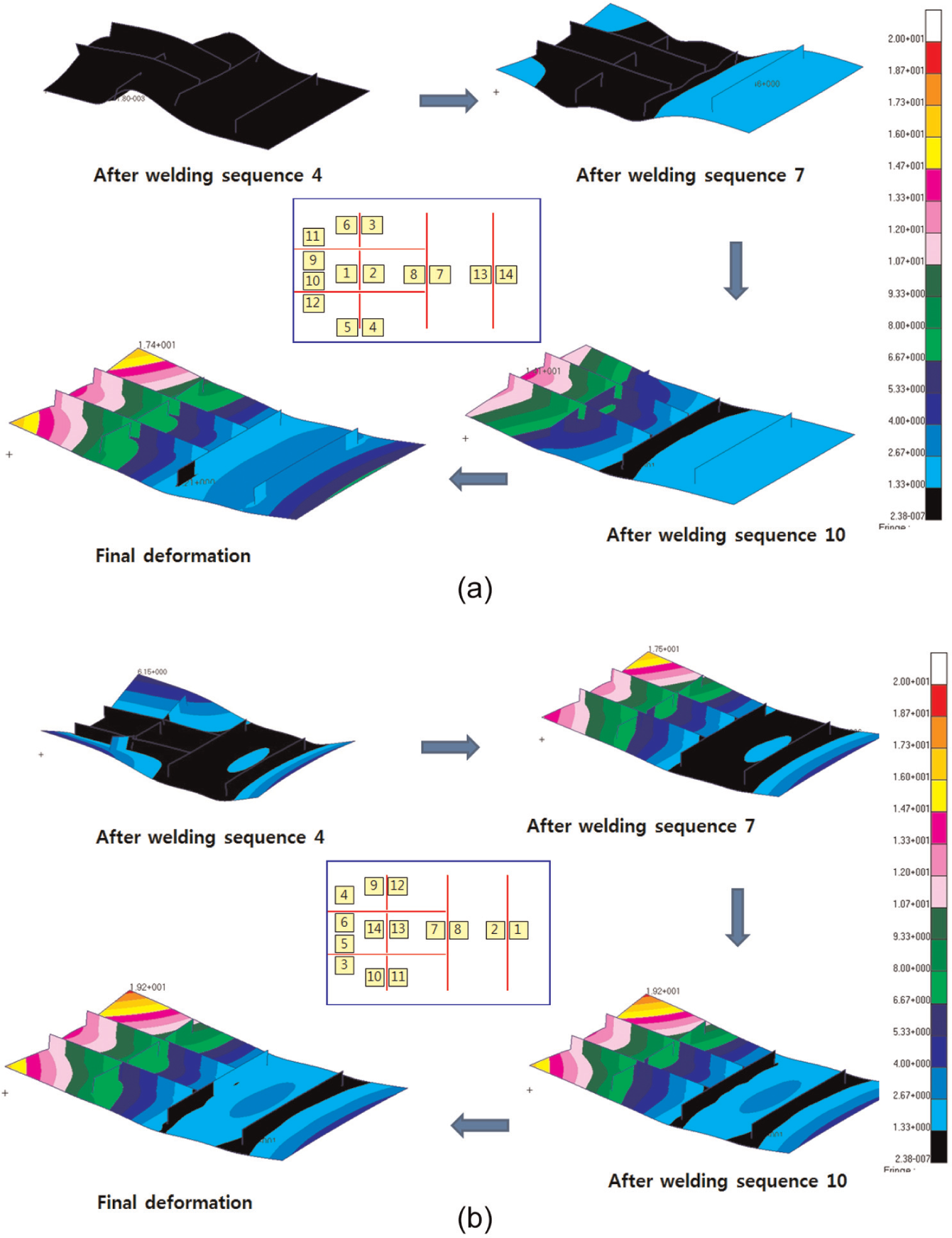
Transient welding distortion of H-type_T1, T2: (a) transient welding distortion of H-type_T1 and (b) transient welding distortion of H-type_T2.
Figure 15 shows welding distortion toward z-axis according to x-axis and y-axis from the measurement point in Figure 13. According to the comparison of welding distortion toward z-axis according to x-axis as in Figure 15(a), distortion at y = 10, 1320 mm was angular distortion due to welding done on the horizontal stiffener. However, almost constant distortion occurred at y = 2990 mm. Also, the comparison result of welding distortion toward z-axis according to y-axis is shown in Figure 15(b), while overall distortion downward occurred for the weld joint by vertical trans_S 1-5. Furthermore, relatively less distortion occurred at x = 1000 mm due to restraint by horizontal Hori_S 1 and S 2.
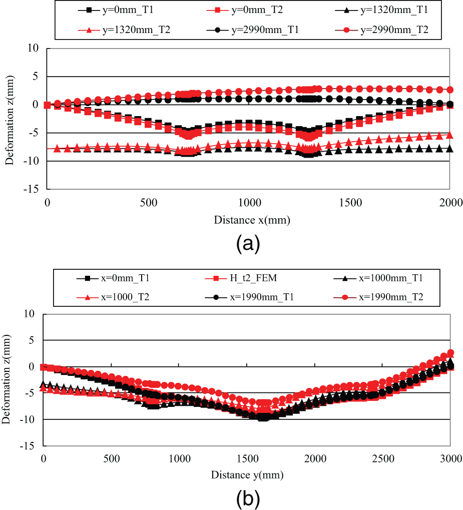
Comparing welding distortion of H-type_T1, T2: (a) welding distortion along x-direction and (b) welding distortion along y-direction.
From the results above, welding distortion of welding sequence H_T1 was relatively less than that by H_T2. Therefore, welding sequence drawn by joint rigidity method by which welding distortion was minimized would be appropriate. However, overall distortion less than 10 mm occurred for small components which were the subjects of this study. Meanwhile, the difference in distortion between H_T1 and H_T2 was less than 5 mm which cannot say that it was a small assembly component affected largely by welding sequence.
Conclusion
A new joint rigidity method model was proposed in this article to investigate the effect of welding sequence on the welding distortion. The reliability of this new model was validated by carrying out welding distortion analysis through experiment and equivalent load method. Also, welding distortion was compared using equivalent load method on the welding sequence drawn by joint rigidity method for small assembly components for ship building. The obtained results are as follows:
A new joint rigidity method was proposed in order to draw welding sequence considering welding sequence of left/right during fillet welding. New joint rigidity method could consider the distance between base plate and stiffener and welding sequence of left/right during fillet welding by setting welding beads at left/right side as separate solid elements.
Welding sequence was drawn by new joint rigidity method and then the experiment for the fillet welding specimen by varied gap between stiffeners and welding distortion analysis by equivalent load method were compared. Comparison results proved that both results were well-matched.
Welding sequence which made welding distortion maximum/minimum was drawn by joint rigidity method for the small assembly components. The welding distortion analysis was then carried out using equivalent load method. A maximum less than 10 mm of welding distortion occurred. Welding distortion less than around 5 mm occurred in welding sequence H_T1 which minimized welding distortion as compared with H_T2, generating maximum welding distortion. The results showed that welding sequence drawing method by unit moment was appropriate.
Welding distortion for small assembly components was affected by welding sequence. Yet, the generated shape in welding distortion was greatly affected by installation location and the direction of stiffeners which were welded on the base plate.
Footnotes
Declaration of conflicting interests
The authors declare that there is no conflict of interest.
Funding
This study was supported by research fund from Chosun University, 2011.