
Abstract
In order to continuously improve the component roundness and productivity, an innovative investigation on through-feed centreless grinding is required particularly towards the 0.1–0.3 µm roundness accuracy of the components in the industrial production scale. In this process, the characteristics of the supporting and driving mechanism for the workpiece make the analysis of workpiece surface generation more complex than other grinding processes. This article presents an innovative approach for investigating the workpiece roundness generation in through-feed centreless grinding. Using homogeneous transformations, the geometries and the movements of the workpiece and the wheels are presented through a three-dimensional simulation model developed by the authors. This model and the associated simulations can be applied to investigate the workpiece kinematics and its rounding process under various geometric configurations and grinding parameters, and to further analyse the influences of these parameters on the workpiece roundness generation.
Introduction
Compared with in-feed centreless grinding, the through-feed centreless grinding is more widely applied in the production of cylindrical components particularly in bearings manufacturing and automobile industries, such as needles, rollers, bearing rings, valve stems and shafts. In this machining process, as the additional auxiliary operations are not required including loading/unloading, adjusting and clamping of the workpiece component, a continuous stream of the workpiece components can thus flow through the grinding zone and higher production rate is achieved, which is crucial for manufacturing a large batch of components. More importantly, the accuracy of the component is tractable and guaranteed under the proper configurations. Using the through-feed centreless grinding, the roundness accuracy of precision rollers (
In centreless grinding, the workpiece kinematics and rounding mechanism are quite dissimilar to fixed centre grinding. Rowe and colleagues2–4 presented the basic equations for the rounding process and an analytical method for deriving stability charts, which can be used for selecting proper grinding configurations. Based on the investigation of the three kinds of stabilities, work rotation stability, dynamic system stability and rounding effect stability, the diagrams were proposed for determining proper set-up conditions.5,6 And the simulation methods were developed to provide the optimal grinding cycle.7,8 Bueno et al. 9 studied the geometric and dynamic stability and presented the influence of machine setup and flexibility on them. Xu and Wu 10 provided a simulation method for analysing the through-feed centreless grinding process performed on a surface grinder, supported with a three-dimensional (3D) simulation model of this process. In order to improve productivity and control of geometric precision, Barrenetxea et al. 11 recently developed new system-level algorithms for selecting optimal setup and grinding cycle of in-feed centreless grinding under multi-criteria. Drazumeric et al. 12 presented an analytical model describing the grinding gap macro geometry and workpiece kinematics, especially the optimal control wheel geometry in through-feed centreless grinding. The workpiece rounding process in through-feed centreless grinding is sensitive to the machine setup and process parameters, and particularly, the complex shape of the control wheel makes accurate prediction and determination of the workpiece motions in the process more challenging. Therefore, it is essential and much needed to investigate the workpiece kinematics, rounding process and the optimal shape of the control wheel in through-feed centreless grinding particularly by taking advantages of the efficient modelling and simulation techniques.
This article proposes an innovative method for investigating the through-feed centreless grinding process. Using the homogeneous coordinate transformation, the workpiece kinematics and the geometric relationship between the time-varying workpiece surface and the geometries of the grinding gap are studied effectively and efficiently. Based on this method, a 3D simulation model for high precision through-feed centreless grinding process is developed, which is evaluated and validated by well-designed grinding trials. In this model, the workpiece movements are described in the form of the position and orientation of the workpiece axis when it contacts with both the workrest and the control wheel. The contacts between them and the workpiece rounding process are calculated according to the grinding gap geometry and especially the real-time workpiece profile in grinding.
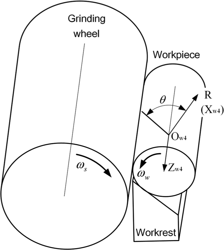
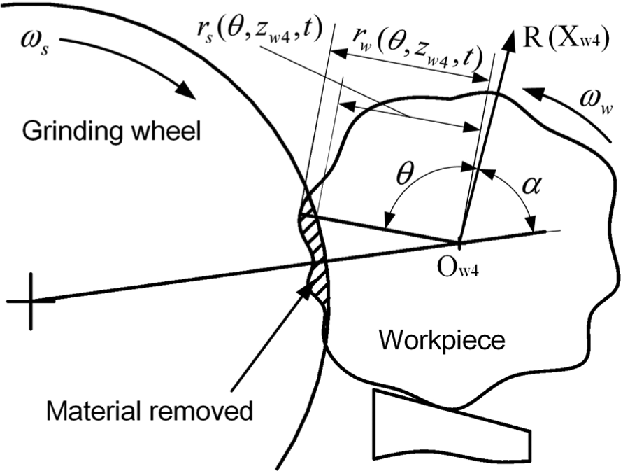
Configuration of the through-feed centreless grinding
The through-feed centreless grinding process is influenced not only by grinding parameters and machine dynamics but also by the machine geometric configurations and particularly the control wheel form. 12 The working principle and configurations of through-feed centreless grinding are illustrated in Figure 1.
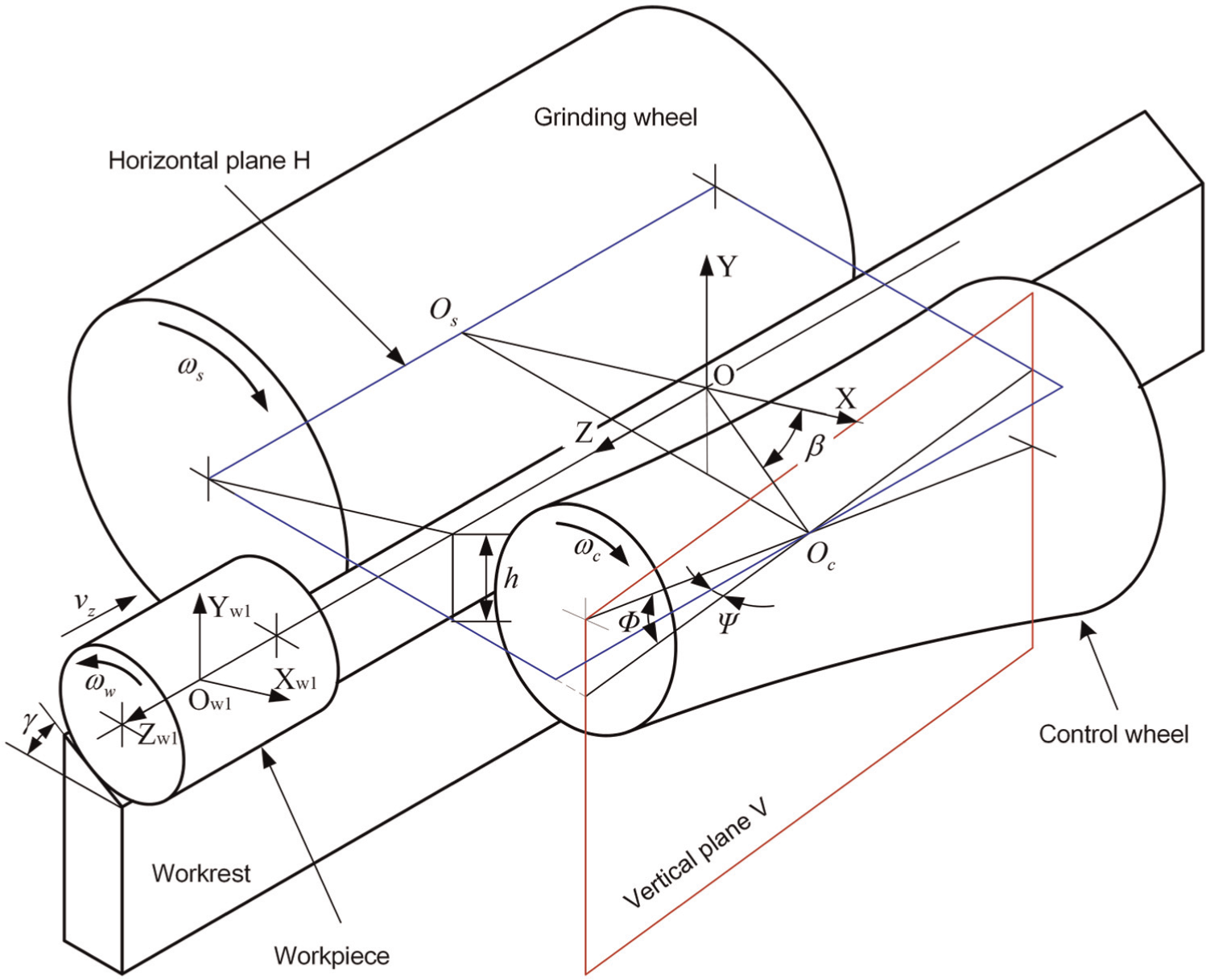
Working configurations in through-feed centreless grinding.
For the effectiveness of rounding action,
13
the workpiece centre is usually set above the grinding wheel and control wheel centres as illustrated in Figure 1. In this figure, the height is represented by h and the speeds of the grinding wheel, the workpiece and the control wheel are
In order to investigate the workpiece kinematics and describe the geometries of the workpiece, the wheels and the workrest, a reference Cartesian coordinate system OXYZ is built as illustrated in Figure 1. The origin point of the coordinate system is located at the intersection point of the apparent workpiece centre line and the vertical plane through the middle point of the grinding wheel centre line. The direction of the OX axis is from the grinding wheel centre point Os to the origin point O. The OZ axis coincides with the apparent workpiece centre line and points at the loading end from the unloading end. Then, the OY axis is determined in the Cartesian coordinate system.
In presenting the equations describing the profiles of the workpiece, the workrest and the wheels, the local coordinate frames are also introduced into each of them, which are detailed in the following sections. The spacial relationship between them must be given. In this article, the transformations of the coordinates of the points in different frames are completed accurately and effectively using homogeneous transformation matrix (HTM) in which the position and orientation between different frames are represented by the elements of the matrix.
Kinematics of the workpiece in through-feed centreless grinding
In the whole grinding process from the workpiece entering the grinding zone till last piece of material being removed, not only the posture of the part but also its profile varies continuously. Presenting the workpiece geometry accurately in real-time is essential to calculate the material removal and the generation of new surface. Some researchers presented the method for calculating the geometric relationship between the grinding wheel and the workpiece, but the model was developed for a special configuration of the process using an ultrasonic elliptic-vibration shoe instead of control wheel and performed on a surface grinder. 10 In this article, the space description and coordinate transformation, which are widely adopted in the study of robot kinematics, are applied to calculate the workpiece geometry and movements accurately and efficiently. Based on this method, the workpiece rigid body movements in through-feed centreless grinding can be described by three translations along the three axes and three rotations about the three axes in Cartesian coordinate system. The three translations determine the position of the body, while the rotations determine its orientation.
In the study of the workpiece kinematics in through-feed centreless grinding, the factors affecting the workpiece movements are taken into account, although the following assumptions are made:
The grinding wheel and the control wheel are trued into the ideal shapes, and the supporting surface of the workrest is a perfect plane. Compared to the material removal of the workpiece, the wear of them is negligible.
The workpiece is constantly supported by the workrest and the control wheel, therefore, the workpiece maintains contacting with them in the grinding process. The contact between the workpiece and the workrest or between the workpiece and the control wheel occurs in two points located at the front half part and rear half part of the workpiece, respectively, which guarantees no penetration between them.
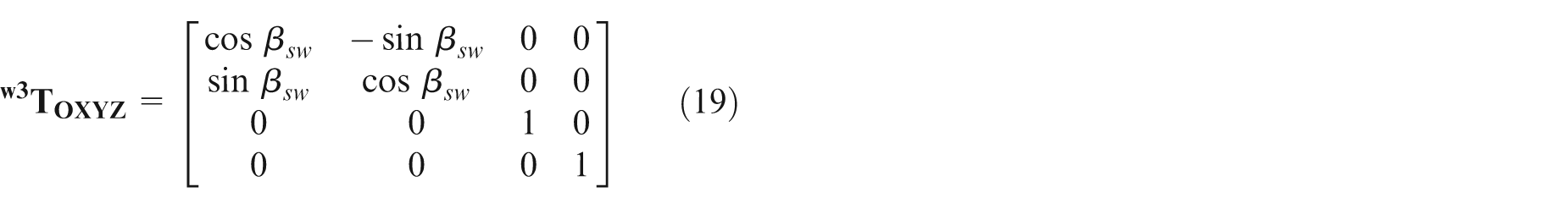
Both the control wheel and grinding wheel rotate at constant speeds, respectively.
No spinning or sliding occurs between the workpiece and the control wheel, and the workpiece motion is controlled by the control wheel.
The vibration of the machine is too small to render influence on the workpiece rounding process, as the machine is robustly designed and installed. The elastic deformation of the grinding system due to the forces is measured by the machining-elasticity parameter
Workpiece movements in contact with the workrest
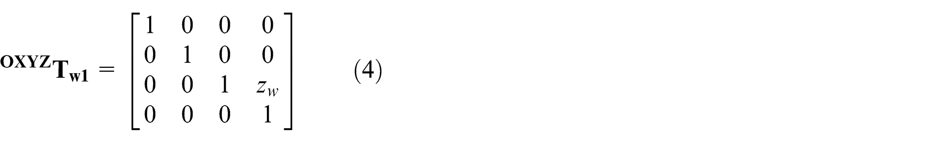
As noted before, the rigid body frame Ow1Xw1Yw1Zw1 attached to the workpiece is used to obtain its translations and rotations relative to the reference coordinate system. This frame is illustrated in Figure 1 and defined as follows. The origin of the frame is located at the centre of the initial ideal axis of the workpiece, and this axis is also selected as the Ow1Zw1 axis. The Ow1Xw1 axis is parallel to OX axis of the reference frame. The initial ideal axis of the workpiece is usually set above the horizontal plane H. The value of the height

Where
In consideration of the workpiece unclamping state, its movements can be resolved into six components: three translations along the axes and three rotations about the axes. During the grinding process, the workpiece instantaneous profile can be obtained by updating the radius of each point in its surface. On the other hand, under stable operation, the workpiece is assumed to move along the Ow1Zw1 axis uniformly. The movement in this direction is given by

where

where Lw and Ls are the workpiece length and the grinding wheel width, respectively. The HTM that transforms the coordinate of a point in the Ow1Xw1Yw1Zw1 coordinate frame into the OXYZ frame is
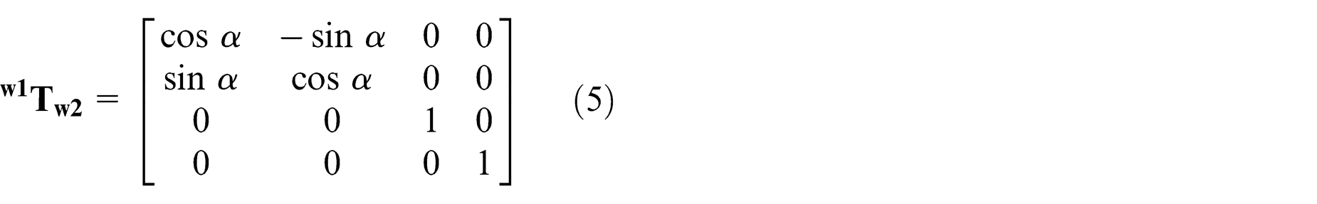
According to the analysis previously, it is concluded that the major work for determining the workpiece movements is to calculate the translations and the inclinations of the workpiece axis. Based on this conclusion, the first step is to provide the movements of the workpiece axis when it contacts to the workrest without consideration of the contact with the control wheel. In other words, the workpiece translation and inclination relative to the workrest supporting surface are calculated in this step. For this purpose, the workpiece frame Ow1Xw1Yw1Zw1 is first rotated about the Ow1Zw1 axis at the angle
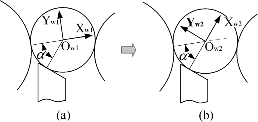
Transformation of the workpiece coordinate frame: (a) coordinate frame OW1XW1YW1ZW1 and (b) coordinate frame OW2XW2YW2ZW2
The Ow2Xw2Zw2 plane of the new frame is perpendicular to the workrest supporting surface now. The HTM that transforms the coordinates of a point in the Ow2Xw2Yw2Zw2 coordinate frame into the Ow1Xw1Yw1Zw1 frame is
Then, in the Ow2Xw2Zw2 plane, the workpiece movements in contact with the workrest can be represented by the rotation about the Ow2Yw2 axis and the translation along the Ow2Xw2 axis. The two movements can be given conveniently by calculating the angle and the distance between the workrest supporting surface and the workpiece contact line lwr as illustrated in Figure 3.
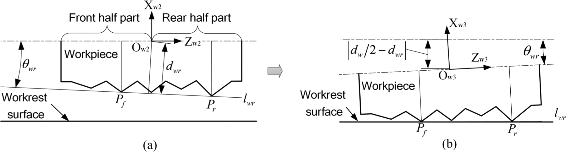
Workpiece movements in contact with the workrest: (a) the initial workpiece position and (b) the workpiece position contacting with the workrest
The workpiece contact line is an imaginary line formed by the two workpiece points contacting with the workrest. As illustrated in Figure 3, the two points can be determined by the following method:
List the Xw2 and Zw2 coordinates of the workpiece profile points (P1
, P2
,…, Pn
) in the Ow2Xw2Zw2 plane and mark the coordinates as (
Select the two points which locate respectively in the front half part and rear half part of the workpiece and have the maximum Xw2 coordinate in its own half part. The two points are marked as Pf and Pr .
Present the equation of the line determined by the two points Pf
and Pr
in the Ow2Xw2Zw2 plane and mark it as
Substitute the Zw2 coordinates of the points (P1
, P2
,…, Pn
) into the equation of the line
Subtract the

The positive value of
Replace the two points Pf
and Pr
by the two which provide the minimum values of
Following the procedure above, the equation of the contact line lwr in the Ow2Xw2Zw2 plane is finally given

where

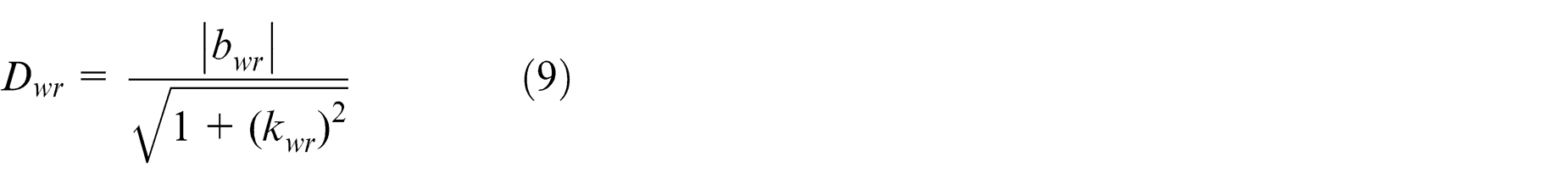
And the distance from the workpiece centre point Ow2 to the contact line lwr is
When the workpiece contacts with the workrest, the contact line

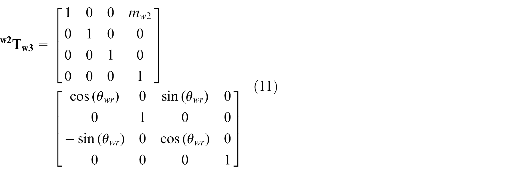
The transformations and the new workpiece coordinate system represented by Ow3Xw3Yw3Zw3 are illustrated in Figure 3. The HTM that transforms the coordinates of a point in the Ow3Xw3Yw3Zw3 coordinate frame into the Ow2Xw2Yw2Zw2 frame is
Ideal control wheel shape
In order to provide stable supporting and effective driving to the workpiece, the ideal contact between the workpiece and the control wheel is expected to be the line contact.
12
This requirement is usually satisfied by truing the control wheel into the ideal shape according to machine setup and workpiece profile. In through-feed centreless grinding, as the control wheel axis is inclined at an angle
The control wheel coordinate frame Oc1Xc1Yc1Zc1 is built and shown in Figure 4. The origin is located at the middle point of the wheel axis. The Zc1 axis coincides with the rotating axis, and the Xc1 axis is in horizontal plane. The required control wheel shape (


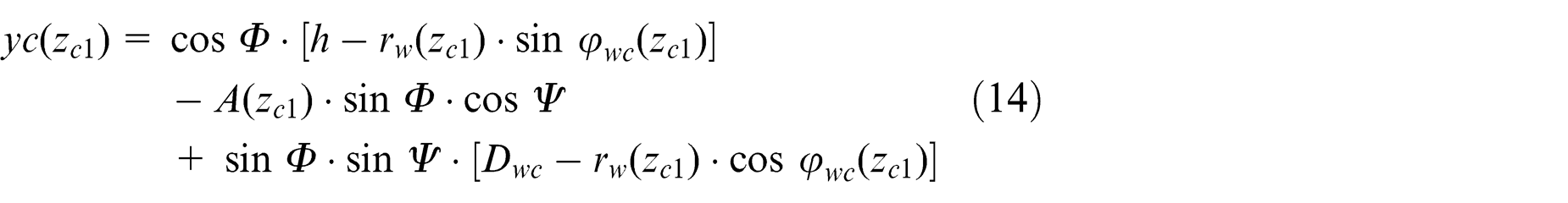

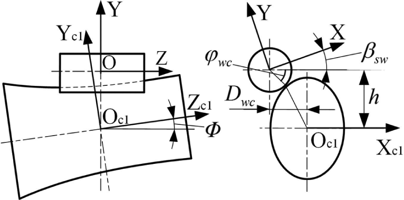
Illustration of the control wheel coordinate frame Oc1Xc1Yc1Zc1.
where
In above equations (12)–(16), the control wheel shape is given in the coordinate frame Oc1Xc1Yc1Zc1. In order to give the control wheel shape in the workpiece coordinate frame Ow3Xw3Yw3Zw3, the transformation from the coordinate frames Oc1Xc1Yc1Zc1 to the reference frame OXYZ needs to be presented. This process is completed by the following steps:
Rotate the Oc1Xc1Yc1Zc1 coordinate system by an amount
Translate the Oc2Xc2Yc2Zc2 coordinate system by an amount
Rotate the Oc3Xc3Yc3Zc3 coordinate system by an amount
Multiplying the HTMs,

If the coordinates of a point in the Ow3Xw3Yw3Zw3 coordinate frame are represented with (Xw3, Yw3, Zw3), its coordinates (Xc, Yc, Zc) in Oc1Xc1Yc1Zc1 frame are given by
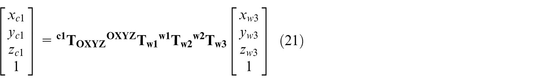
In equation (21), the Xc1 and Yc1 coordinates are expressed by Xw3, Yw3 and Zw3, and
Workpiece movements in the grinding zone
The workpiece movements in contacting with both the workrest and the control wheel significantly influence the rounding process. However, due to the considerable error on the workpiece surface and particularly the complex surface of the control wheel, the contact between them and the workpiece movements become especially complex and need to be investigated meticulously. In this section, the movements are calculated with the assumption that the control wheel is trued into the optimal shape described by equations (12)–(16).
Contacting with the workrest, the workpiece is constrained to slide along the supporting surface and move towards the control wheel. Therefore, the workpiece movements from the position contacting merely with the workrest to the position contacting simultaneously with the workrest and the control wheel can be calculated in the Ow3Yw3Zw3 plane as illustrated in Figure 5.
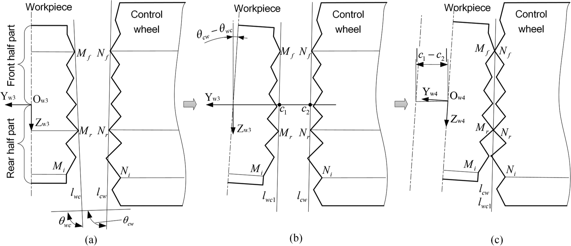
Workpiece movements in contact with the control wheel: (a) the initial workpiece position, (b) the workpiece rotation and (c) the workpiece position contacting with the control wheel
The contact between the workpiece and the control wheel is inevitably influenced by the workpiece profile and the complex curvature of the control wheel. This situation is illustrated in Figure 5. In the Ow3Yw3Zw3 plane, the points on the workpiece and control wheel surfaces are represented by


where
When the contact between the workpiece and the control wheel occurs, the two contact lines
First the workpiece and the line

The intercepts of lines


Second, the workpiece and the line lwc1
are translated by an amount
For convenience, the values of the two transformations are represented by


The HTM that transforms the coordinates of a point in the Ow4Xw4Yw4Zw4 coordinate frame into the Ow3Xw3Yw3Zw3 frame is
The HTM that transforms the coordinates of a point in the Ow4Xw4Yw4Zw4 coordinate frame into the OXYZ frame is obtained by multiplying the HTMs

In the beginning of grinding process, the coordinates of the workpiece surface points are given in the Ow1Xw1Yw1Zw1 coordinate frame. After it contacts with both the workrest and the control wheel, the coordinates of the workpiece surface points in the OXYZ reference frame are calculated by
New modelling on the workpiece surface generation
In through-feed centreless grinding, as the workpiece passes through the grinding zone, the material is removed gradually. In different workpiece cross-sections, the roundness generation shows various features. And the workpiece posture and position vary continuously during the grinding time. The study of workpiece rounding action is expected to be carried out around the circumference and along the axis. In this work, the workpiece is equally divided into a number of cross-sections along the axis, and in each cross-section, the circumference is discretized into a series of segments. Consequently, during the entire grinding process, the real-time regeneration of every point on workpiece surface can be investigated.
For the precision and convenience in calculation, the workpiece surface is described in the cylindrical coordinate frame shown in Figure 6, which is transformed from the Ow4Xw4Yw4Zw4 coordinate frame. For a workpiece surface point with a polar angle

Workpiece cylindrical coordinate frame.
where
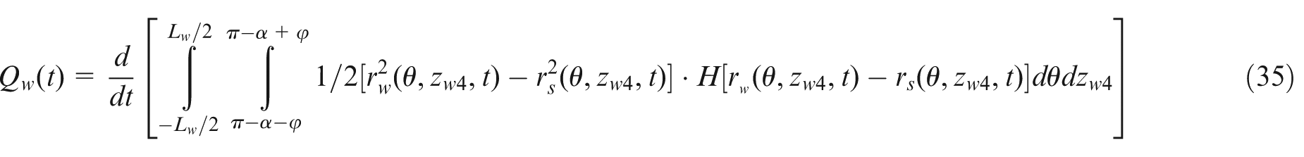
where
Workpiece surface regeneration.
Acted by the normal grinding force, the grinding wheel and the workpiece are pushed away from each other. The relative movement between them is given by

where

The workpiece surface is updated by the equation

Simulation strategies and results
Based on the model developed in previous sections, the theoretical research is carried out to investigate the workpiece roundness generation in through-feed centreless grinding operations. As noted above, the workpiece surface in simulations is discretized into a number of segments along the workpiece axial and circumferential directions. For example, the workpiece is equally divided into Nc segments around the circumference and Na cross-sections along the axial direction. Then, the time step is

where
The model is implemented in MATLAB programming environment which provides high efficiency and accuracy in numerical calculation. In this environment, the initial parameters of the grinding process are input through graphical user interface (GUI). Then, surface generation is simulated based on the developed model. When the analysis is completed, the regenerated workpiece surface is presented and the roundness error in every cross-section is calculated by least square method (LSM).
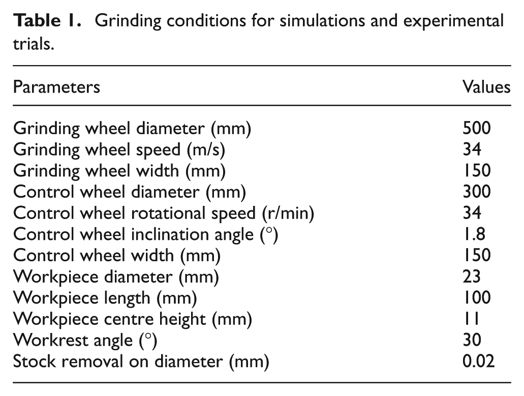
The cylindrical workpiece with a flat of depth of 18 µm along the length is used in the simulations. This initial shape contains sufficient harmonics with different amplitudes and orders. And the harmonics predominate over other initial effects. The selection of this shape makes it possible that the elimination of the harmonics during grinding can be investigated. On the other hand, the workpiece with this shape can be prepared easily in practice, which implies that the effective experimental verification for the model can be made. Because the process is very sensitive to machine setup, the selection of proper configurations is particularly important. The conditions for simulations are listed in Table 1 as recommended with taking account of the process optimization.15,16 The control wheel is not swivelled in the horizontal plane. Due to the inclination of the control wheel axis, the tangent angel and the control wheel diameter vary all along the workpiece path. And the workpiece rotation and feeding are controlled by the control wheel. For the conditions listed in Table 1, the tangent angle in OXY plane is 6.3° and the control wheel diameter is the value measured on its front face. Using the method recommended in Drazumeric et al.,
12
the workpiece rotational speed is calculated, which varies from 443.3 to 445.2 r/min. And the feed rate changes from 16.75 to 16.79 mm/s. The machining-elasticity parameter
Grinding conditions for simulations and experimental trials.
Due to the machine elasticity and the inclination of the workpiece axis in the grinding process, when the different workpiece cross-sections pass through the same Z position their grinding situations are dissimilar. This implies that the same cross-section of the control wheel will support the workpiece cross-sections with different diameters in the workpiece feeding process. In the truing of the control wheel, the workpiece diameter along the feeding path is considered constant.
The workpiece profiles of selected cross-sections are shown in Figure 8. As the workpiece passes through the grinding zone, the material is removed gradually along the axial direction. Although there is no difference between the initial cross-sections, this situation is changed during grinding process. Consequently, the surface generation and ground profiles are dissimilar between the cross-sections which can be observed in Figure 8.
Theoretical workpiece profiles in selected cross-sections: (a) 15 mm, (b) 50 mm and (c) 85 mm.
At the beginning of the grinding, the workpiece deviation from apparent position is mostly determined by the unground surface. In this stage, the initial roundness error significantly influences the workpiece position and posture. After the workpiece enters the grinding zone in axial direction, the initial irregular shape is improved and the error is reduced gradually as illustrated in Figure 9. Supported by the improved surface, the workpiece inclination relative to the workrest supporting plane and the control wheel is not as severe as that in the beginning stage. Therefore, the roundness errors in the cross-sections of the rear part of the finished workpiece are a little smaller than those in the cross-sections of the front part.
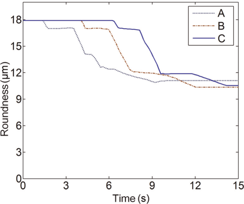
Variation of roundness of the workpiece cross-sections in selected axial positions: (a) A: 15 mm, (b) B: 50 mm and (c) C: 85 mm.
Experimental evaluation and validation
Experiments were carried out to verify the effectiveness of the model obtained in previous sections. The conditions for simulations listed in Table 1 were used in the grinding trials. In preparing the workpieces with a flat, they were first ground to reduce the roundness error within 2 µm. Then, the flat was machined by a surface grinder. The grinding trial setup with the detailed process variables is illustrated in Figure 10.
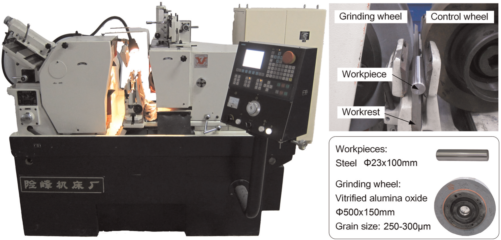
Illustration of the grinding trial setup and process variables.
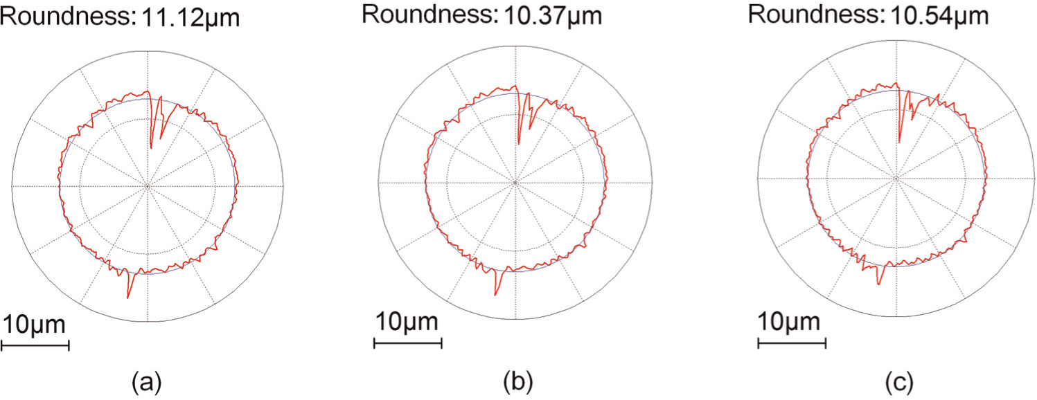
The experimental workpiece profiles are presented in Figure 11. Comparing the experimental results with the theoretical results, good correlations between the two are shown both in the shapes and magnitudes of roundness errors. The differences between them probably derive from the initial workpiece roundness errors. And the profiles of the wheels and the workrest supporting surface in grinding trials are not ideal, which can inevitably influence the workpiece movements and the roundness generation. The experimental results also show that the roundness in the middle of the workpiece is largest, which is dissimilar to the simulation result. The reason for this difference can be given by analysing the workpiece movements in contact with the workrest and the control wheel. Because of grinding forces acting in grinding trials, the contact between the workpiece and workrest or between the workpiece and control wheel might not constantly occur respectively in the front and rear half parts of the workpiece, which caused difference from the simulation model. During the stage of the workpiece entering into the grinding zone, the workpiece might be supported with the part which was being ground in the grinding zone. For this part of the workpiece, the severest oscillation was at the position of the grinding zone entrance towards the middle of the workpiece. As the whole workpiece going into the grinding zone, the depth of cut and the grinding forces on the workpiece rear half part became greater than those on the workpiece front half part. In this scenario, the workpiece might be supported with its rear half part. Because most of the required material removal in the workpiece front part had been completed, the workpiece movements had the worst influence on the roundness improvement in the middle of the workpiece. Consequently, the final roundness error in the middle of the workpiece is the largest compared to other workpiece positions. Besides the reasons above, the dynamic responses of the grinding machine and the position errors of the guide plates placed at the loading and unloading ends were two possible reasons for this difference.
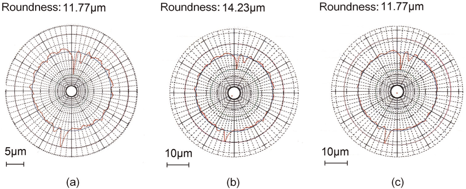
Component profiles in selected cross-sections: (a) 15 mm, (b) 50 mm and (c) 85 mm.
Conclusions
This article presents an innovative approach to the investigation of workpiece kinematics and the associated workpiece roundness generation in high precision through-feed centreless grinding. The investigation is carried out through novel modelling of the workpiece kinematics in relation to the rounding process, 3D simulations and evaluation and validation of the approach with well-designed grinding trials. The conclusions can be drawn specifically as follows:
An innovative approach is presented for investigating the workpiece kinematics and rounding process in through-feed centreless grinding. This approach first utilizes the homogeneous coordinate transformation to present the geometries of the grinding wheel, the workrest, the control wheel and the time-varying profile of the workpiece in the unique global coordinate frame. Then, according to their geometries in this frame, the contacts of the workpiece with both the workrest and the control wheel are determined. The workpiece movements, including the translations and inclinations, are obtained at this moment. Finally, the workpiece surface regeneration is calculated based on the interference between the workpiece and the grinding wheel.
The grinding trials are designed and performed to verify the 3D model and associated simulations. The workpiece profiles obtained theoretically are shown in a good correlation with the experimental grinding trial results, which indicates that the proposed modelling and simulation approach can accurately and efficiently describe the geometries of the grinding gap and the workpiece, calculate their geometric relationships and the workpiece movements and predict the rounding process. The proposed tool can lead to further understanding of the through-feed centreless grinding processes particularly towards 0.1 µm roundness accuracy with high industrial throughput.
Footnotes
Appendix 1
Acknowledgements
The authors would like to thank Xianfeng Machine Tools Company Ltd for providing the CNC centreless grinding machine and the technical support in grinding trials for this research.
Declaration of conflicting interests
The author(s) declared no potential conflicts of interest with respect to the research, authorship, and/or publication of this article.
Funding
The author(s) received no financial support for the research, authorship, and/or publication of this article.