
Abstract
Continuous improvement of the component roundness accuracy through computer numerical control centreless grinding in high productivity is one of the most important issues particularly for modern automotive and bearings manufacturing. For instance, the process is towards 0.1–0.3 µm roundness accuracy in grinding the engine valve rod because of the increasingly stringent energy efficiency requirement in automotive engines. The characteristics of the computer numerical control centreless grinding process make it challenging, that is, how to assure the workpiece roundness generation in a predictable, producible, highly productive and scientific manner. In this article, a simulation-based industrial feasible approach is presented to model and control the workpiece roundness generation and its perfection strategies in computer numerical control centreless grinding. The kinematics of the workpiece in the process is presented according to the workpiece profile and its geometric configurations. Taking into account the workpiece geometric movements, contact and loss effect and grinding restrictions, a time-domain dynamic model is developed to provide the dynamics description of the workpiece, the grinding wheel and the control wheel in the process. The roundness generation of the workpiece is further predicted using this model. The effects of multiple factors on the workpiece rounding process are discussed and the influences on final roundness errors are investigated.
Introduction
Centreless grinding technology is widely applied to machining the external or internal surfaces of the cylindrical workpieces under both high productivity and high accuracy particularly in bearings and automotive manufacturing industries. For instance, the process is currently pursued towards 0.1–0.3 µm roundness accuracy in centrelessly grinding the engine valve stem because of the increasingly stringent energy efficiency requirement in automotive engines. Usually, the improvement in the workpiece roundness accuracy is accompanied by higher quality and productivity; therefore, the workpiece roundness is considered as the most important indicator of the process. 1
The workpiece supporting system and the driving mechanism for the workpiece rotation perform the uniqueness for the workpiece surface generation, which are quite dissimilar to other machining methods. Compared with the fixed centre grinding, centreless grinding process is more sensitive to the wheel’s properties, geometric configurations and machine dynamics. The process stability has been investigated by many researchers2–6 and is characterized by the chatter stability, lobing stability and work-holding stability.7,8 But the stability study is usually carried out in frequency domain with little consideration of nonlinear effects. Some time-domain simulation models have been developed for the investigation of the workpiece forming.9–12 However, the significant factors and their collective influences on roundness generation have not been appropriately investigated, albeit they are critical and essentially important particularly in working towards 0.1–0.3 µm roundness accuracy through centreless grinding.
The research presented in this article aims to develop a simulation-based industrial feasible approach to the workpiece roundness generation and its perfection strategies in computer numerical control (CNC) centreless grinding, which is essentially important for achieving 0.1–0.3 µm roundness accuracy in centreless grinding through a predictable, producible and highly productive scientific manner. In the approach, the workpiece geometric and dynamic movements are presented by incorporating the grinding restrictions with the interactions among the workpiece, wheels and workrest. According to the time-varying positions and profiles of the workpiece and grinding wheels, the workpiece forming process is investigated. The experimental trials are carried out to further validate the model and simulations. The significance of the spindle bearings’ stiffness is discussed using the model and simulation.
Workpiece kinematics in the process
The basic centreless grinding process is illustrated in Figure 1, in which the workpiece is pushed into the grinding position without requirements for adjusting and clamping. The workpiece is supported by the workrest and its rotational and longitudinal movements are driven by the control wheel. With respect to the feed processes, there are two types of centreless grinding, that is, through-feed centreless grinding and in-feed centreless grinding. In the former process, the grinding wheel and control wheel are set at fixed locations and the workpiece moves axially through the grinding space between the two wheels. The axis of the control wheel is inclined at a small angle in vertical plane to drive the workpiece passing through the grinding space. In in-feed centreless grinding process, the workpiece moves towards the grinding wheel to accomplish the feed process and it has no axial motion. The inclination angle of the control wheel can supply the workpiece the motion against the end-stop placed for axial location, which is required particularly in stepped shaft grinding. The in-feed centreless grinding process is mainly concerned in this research.
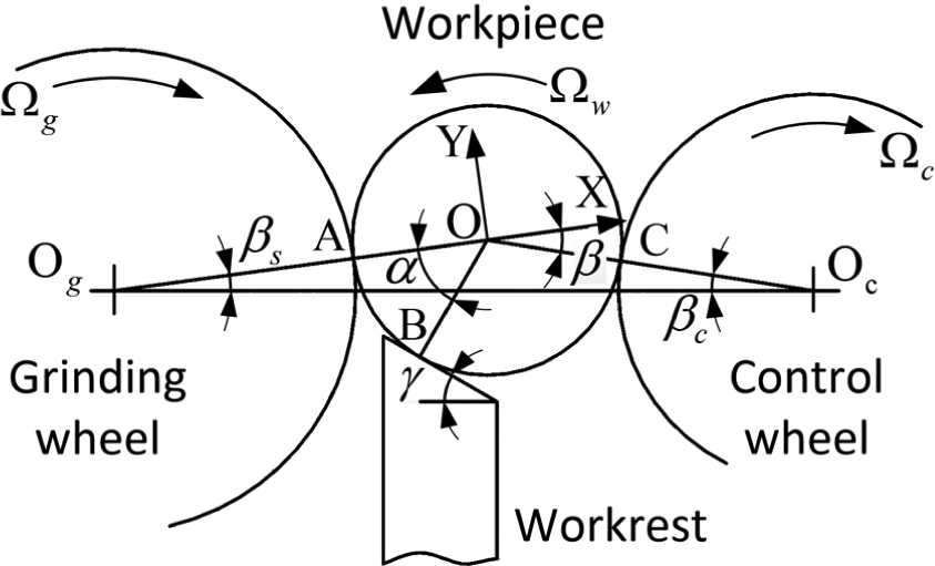
Illustration of the basic centreless grinding process.
The two most important geometric parameters influencing rounding process include workrest angle
Because of the considerable roundness errors on workpiece profile and the unfixed workpiece rotational axis, the errors in contact with the workrest and the control wheel result in the movement of the workpiece to the grinding wheel. Consequently, the movement will influence the regeneration of the new workpiece surface. In order to determine this workpiece movement, a static two-dimensional coordinate system XOY is built, as shown in Figure 1. In this coordinate system, the origin is located at the initial centre of the workpiece with perfect circle. The direction of the X-axis is from the initial centre position of the grinding wheel to that of the workpiece. The direction of the Y-axis is upwards perpendicular to the X-axis.
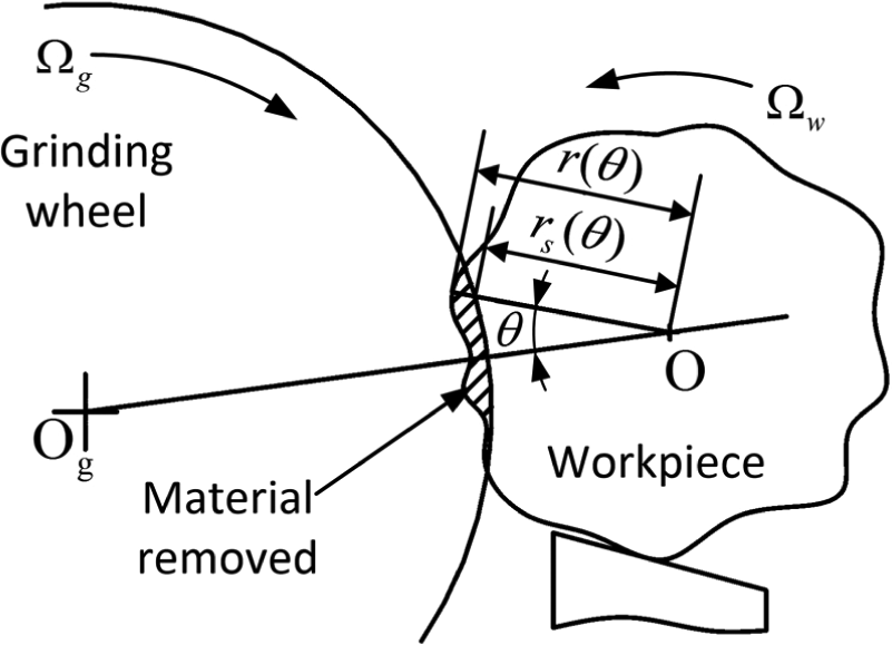
Due to the variation of the workpiece radius at points B and C, the workpiece moves towards or away from the grinding wheel, as illustrated in Figure 2. As there is an irregularity

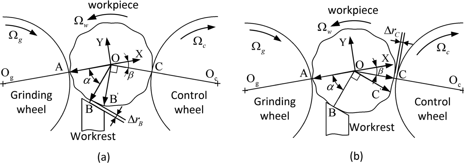
Geometric workpiece movements in the process: (a) workpiece movement due to the radius variation at point B and (b) workpiece movement due to the radius variation at point C.
where
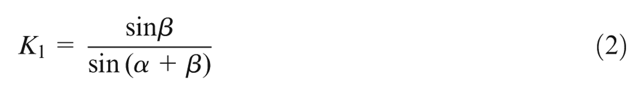
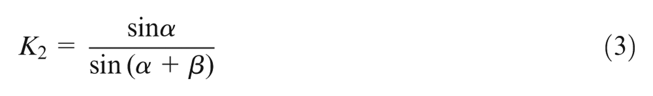
Because the angle
The in-feed motion can be implemented through either the grinding wheelhead slideway or the control wheelhead slideway in horizontal direction. As shown in Figure 3, when the control wheel and the workrest along with the slide move against the grinding wheel in horizontal direction during the feeding process, the feed rate in direction OA,

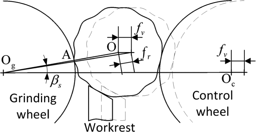
Illustration of in-feed movement in the process.
The apparent depth of cut,
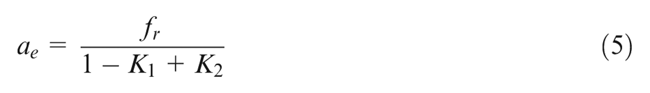
As the workpiece surface material is removed gradually in the process, the workpiece moves towards the workrest-supporting surface and the control wheel. Unlike the fixed centre grinding, the workpiece radial reduction is not equal to the in-feed travel. When the control wheel and the workrest together move horizontally towards the grinding wheel, it provides the in-feed movement as required for the stock removal
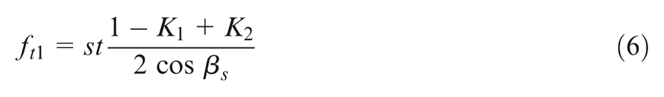
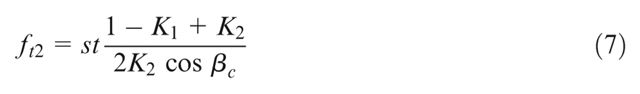
When the in-feed motion is implemented through the control wheelhead slideway with both the grinding wheel and the workrest remaining fixed in position, the total in-feed travel of the control wheelhead slideway
Due to the roundness errors on the workpiece circular surface, the actual workpiece contact point to the workrest-supporting surface does not locate on the line through the workpiece centre and perpendicular to the workrest-supporting surface, as shown in Figure 4. The actual contact point is the one providing the maximum distance from the workpiece centre to the workrest-supporting surface.
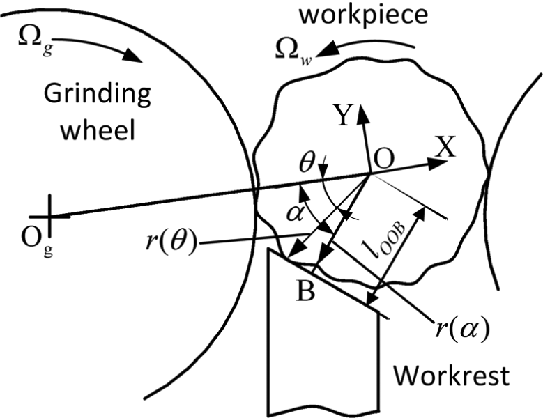
Contact between the workpiece and the workrest.
The geometric displacement of the workpiece centre towards the supporting surface is described as
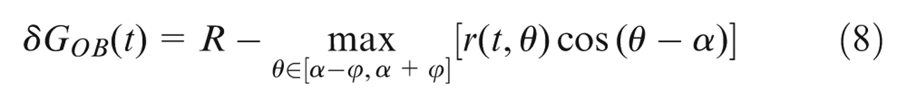
where
The situation of the contact between the workpiece and the control wheel is dissimilar to that between the workpiece and the workrest. The surface distance between the workpiece and the control wheel in the centreline direction varies along with the curvature of the control wheel arc, as shown in Figure 5. The actual workpiece contact point to the control wheel is the one providing the maximum distance from the workpiece centre to the control wheel centre. The geometric displacement of the workpiece centre towards the control wheel centre is
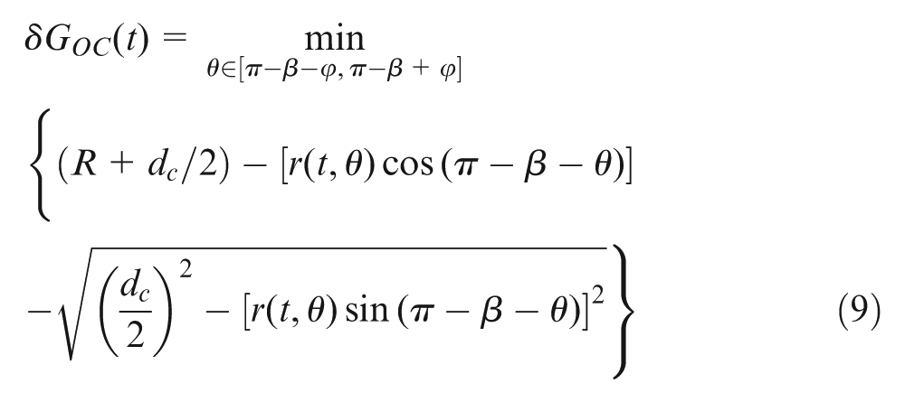
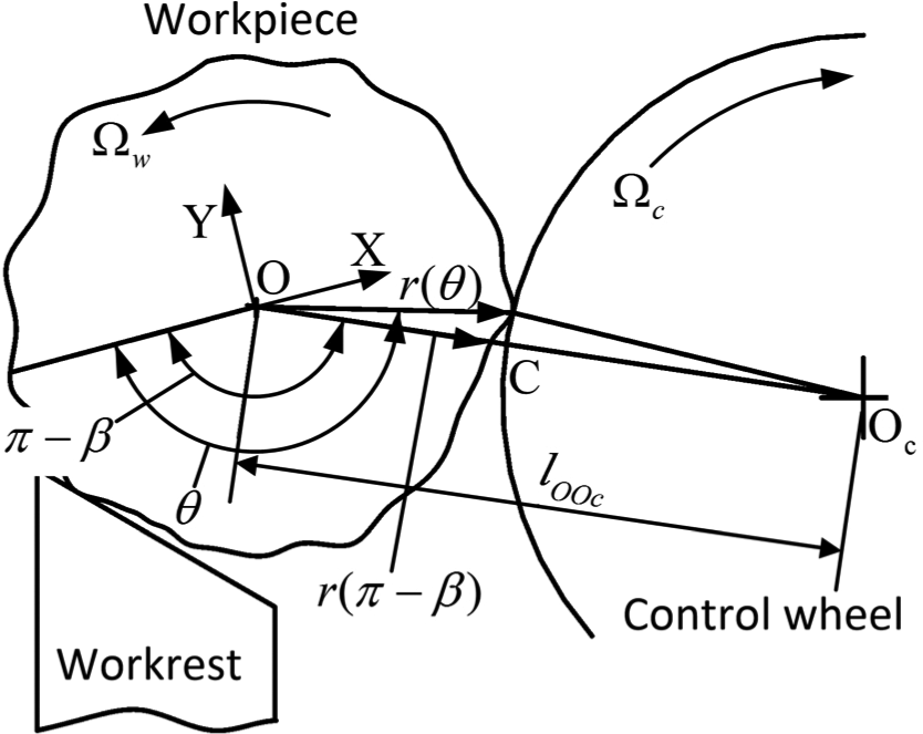
Contact between the workpiece and the control wheel.
where
Workpiece dynamics in the process
The supporting and driving mechanisms of the workpiece motion in centreless grinding make the process sensitive to multiple factors. It is important to take into account all the key factors. In this research, we consider as many factors as possible, particularly some nonlinear elements, although the following assumptions are made in the modelling and simulation. In in-feed centreless grinding, the working conditions vary little in different workpiece cross sections along the workpiece axis; the workpiece rounding process dynamics is therefore studied in one cross section with the assumptions on the section, as follows:
The profiles of the grinding wheel and the control wheel are ideal round.
The supporting surface of the workrest is a perfect plane.
The control wheel and the grinding wheel rotate at corresponding constant speeds.
All springs and dampers behave in a linear form.
No spinning or sliding occurs between the workpiece and the control wheel, and the operation is stable.
The workpiece radius reduces little so that the workpiece mass and centre of gravity do not change in the grinding process.
The volume of the material removed from the grinding wheel is negligible, and the value of the grinding wheel diameter is constant.
The instantaneous tangential and normal grinding forces are proportional to the volume of the material ground from the workpiece surface per unit time.
The workpiece contacts at a single point with both the workrest and the control wheel if the contacts between them occur.
The assumptions above are coherent and consistent with high-precision centreless grinding in the stringently controlled operation conditions. The workpiece dynamic motions are the responses to the interactions among the workpiece, the grinding wheel, the workrest and the control wheel. In this process, the tangential and normal grinding forces are considered as the active forces acting on the machining system. Many grinding force models have been developed and applied to certain conditions. Among these models, many parameters perform correlations with the grinding force, such as the dressing lead, the dressing depth, the grinding wheel diameter and the depth of cut. In order to improve the simulation efficiency, a simplified and condense grinding force model is used. The tangential and normal grinding forces,

where
Acted by the grinding force, the workpiece and the grinding wheel oscillate and the relative position between them is inconstant. Meanwhile, due to the workpiece roundness errors, the points in the valley of workpiece surface are not ground. The grinding process is the consequence of the interference between the workpiece and the grinding wheel. The interference area is calculated by
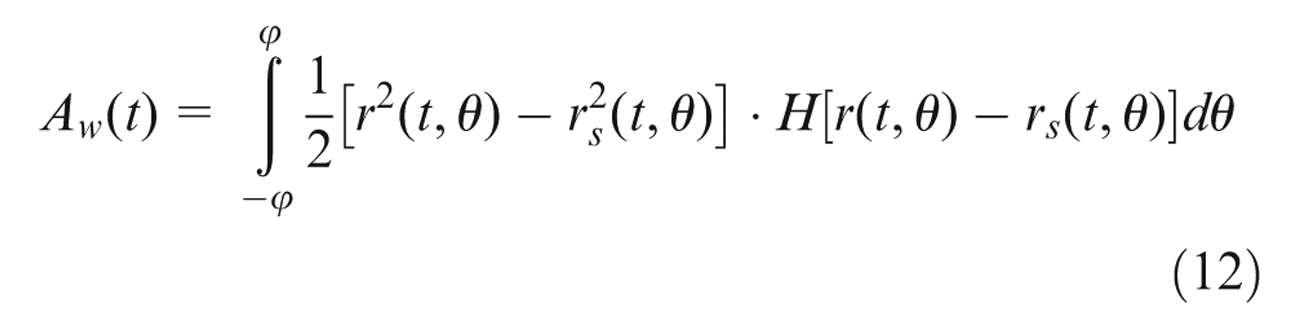
where
Interference between the workpiece and the grinding wheel.
The instantaneous material removal rate

where
The major machine compliant elements causing deflection include the grinding wheel, the control wheel, the bearings and the spindles. Acted on by the forces, the grinding wheel and the control wheel vibrate around the corresponding equilibrium positions, and the dynamic motions of the wheels influence the workpiece roundness generation through the interactions between them. In this research, a new time-domain model is developed to simulate the dynamic movements of the compliant elements in the force loop, as illustrated in Figure 7.
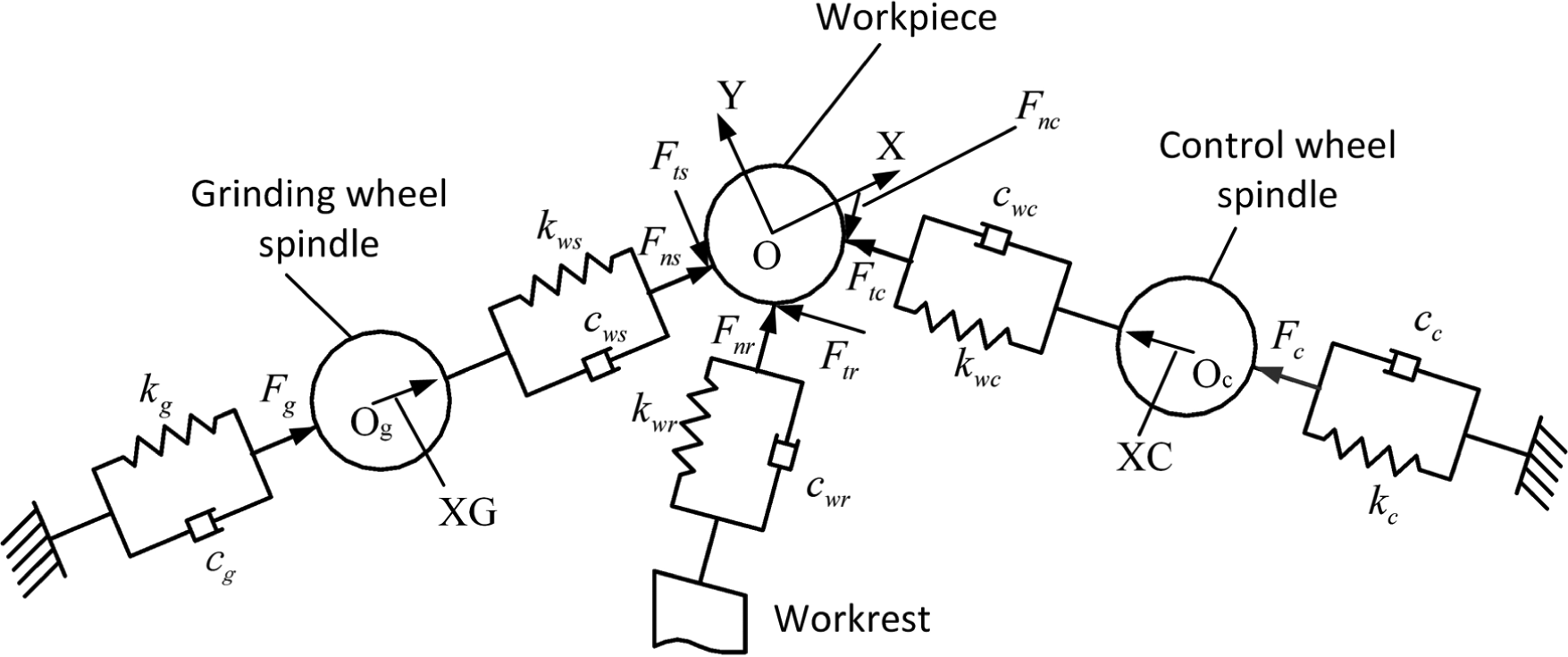
Illustration of modelling the workpiece dynamics.
In this model, the workpiece dynamic movements are described by two components in the X-axis and Y-axis directions. The normal interactions from the workpiece to the grinding wheel spindle, the workrest and the control wheel spindle are represented by springs and dampings. Because the grinding wheel and the control wheel spindles deflect more severely than the wheelheads in grinding process, the dynamic motions of the wheel spindles are modelled by connecting the spindles to the wheelheads with springs and dampings. The grinding wheel movement particularly in the XG-axis direction performs significant effects in the workpiece roundness generation and is considered. Similarly, the control wheel movement in the XC-axis direction is needed to be calculated.
In determining the dynamic responses of the parts, the forces between them are required. In the model shown in Figure 7, the normal and tangential forces,

The compression between the workpiece and the grinding wheel spindle,

where
The instantaneous distance from the workpiece centre to the workrest-supporting surface is

where (
Compared to the initial distance between them, the instantaneous workpiece movement to the workrest is

The actual compression between the workpiece and the workrest-supporting surface is obtained by subtracting the geometric displacement
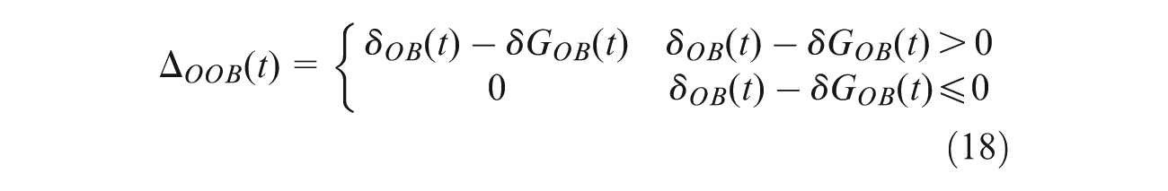
When the value of

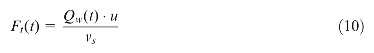
where
Then the tangential force between the workpiece and the workrest-supporting surface is given by

where
Similarly, the compression and the forces at the contact between the workpiece and the control wheel are obtained. In the XOY system, the coordinates of the control wheel centre (

The instantaneous distance from the workpiece centre to the control wheel centre is

In order to calculate the actual compression, the instantaneous workpiece movement in direction OC is given

The value of compression between the workpiece and the control wheel spindle also satisfies the restriction of contact and loss
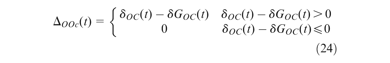
The normal force between them,

where
In stable operation, there is no sliding between the workpiece and the control wheel, and the workpiece rotates at a constant speed. Therefore, the forces acting on the workpiece balance for its rotation. The rotation is controlled by the tangential force and not affected by the normal force directly. Under these conditions, the tangential force

The forces between the grinding wheel and the grinding wheelhead and between the control wheel and the control wheelhead,


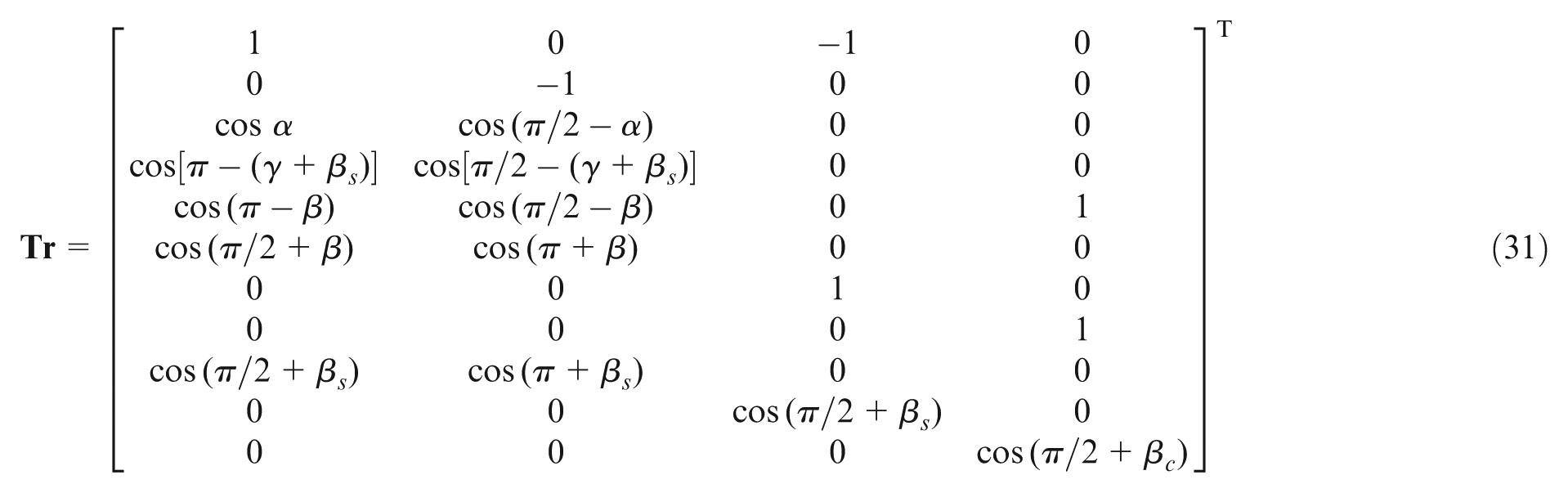
Based on the model shown in Figure 7, the dynamics of the system is described by the system of four differential equations

where

where g is the acceleration of the gravity. The vector consists of all the forces in the model, and the directions of the forces are illustrated in Figure 7. The matrix
After solving equation (29) in time domain, the movements of the workpiece and the control wheel are determined, and then the positions of the points on the workpiece and the grinding wheel surface in grinding area at time

Only the workpiece point with the value of
Validation through experimental trials
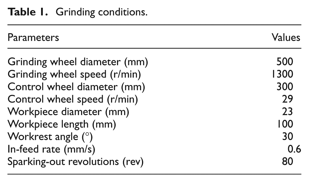
In order to evaluate and validate the time-domain simulation dynamic model, simulation and well-designed grinding trials are carried out to systematically investigate the workpiece roundness generation and perfection strategies. In time-domain simulations, time is usually discretized into a number of steps according to the consideration of efficiency and accuracy. Correspondingly, the workpiece circular surface is divided into the segments with the central angle equal to the rotating angle in each time step. In the simulations, the number of steps in one revolution was selected to be 3600. The details of the grinding conditions used in simulations and experimental trials are listed in Table 1.
Grinding conditions.
The experiments were carried out on a universal centreless grinding machine, as shown in Figure 8. An aluminium oxide grinding wheel and steel workpiece were used in the experiments. The hydrodynamic bearings with high stiffness and high damping are employed on both the grinding wheel spindle and the control wheel spindle.
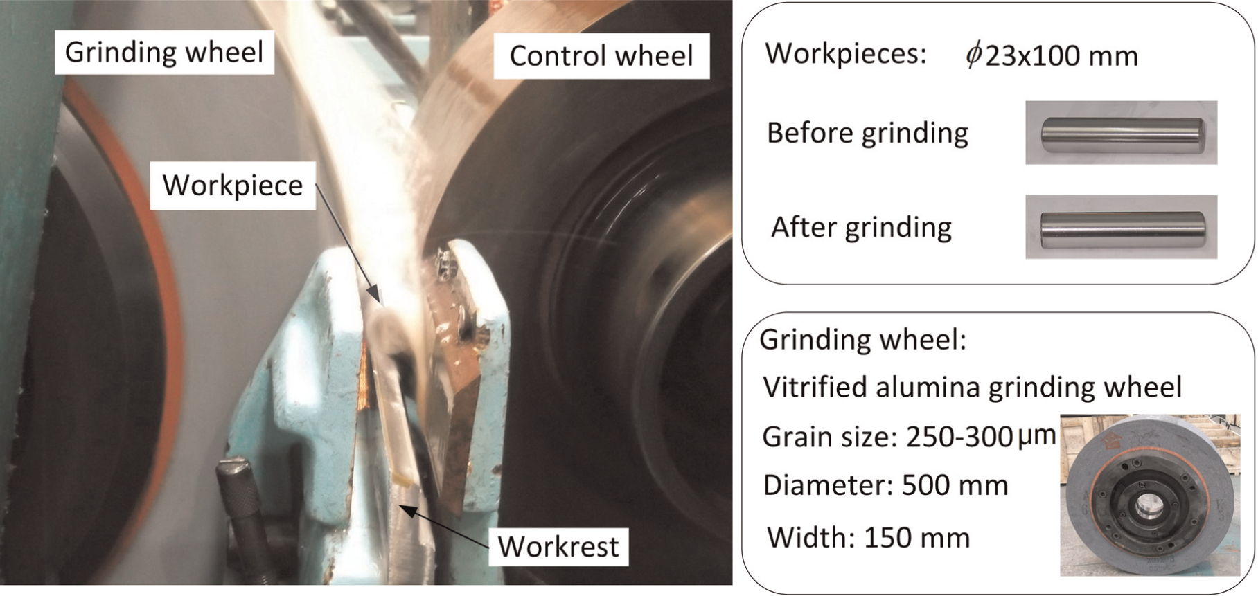
Illustration of the grinding trial set-up.
The pre-grinding shape of the workpiece was with a flat of depth of 18 µm. The sudden in-feed was employed that the feed movement was accomplished in short time with a higher in-feed rate. The selection of the workpiece shape and the in-feed type made the workpiece oscillate more severely in grinding zone. In this situation, the model was verified more effectively. The theoretical and experimental results are shown in Figures 9–11.
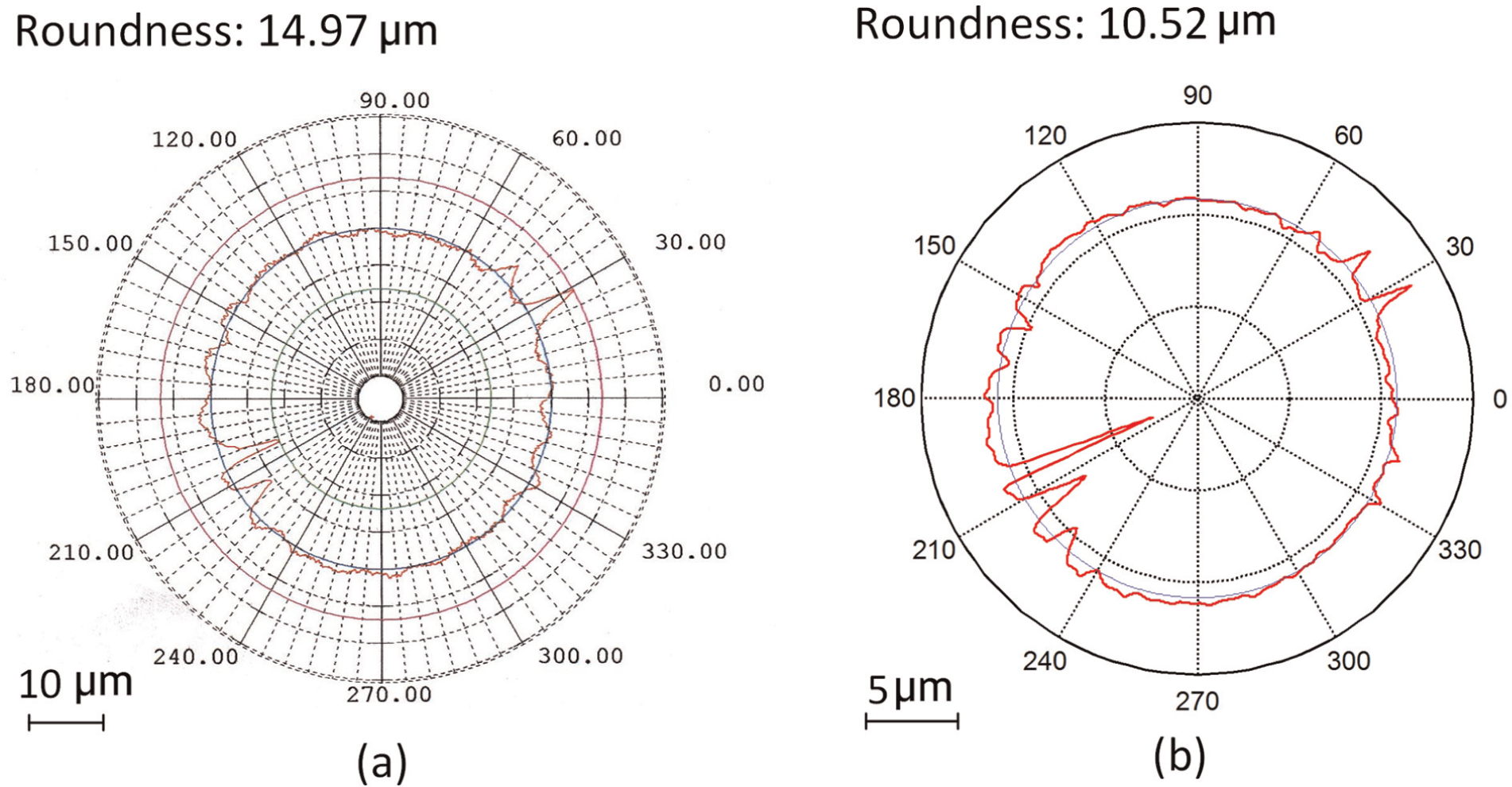
Workpiece profiles for tangent angle of 6° and removal of 0.02 mm: (a) theoretical and (b) experimental.
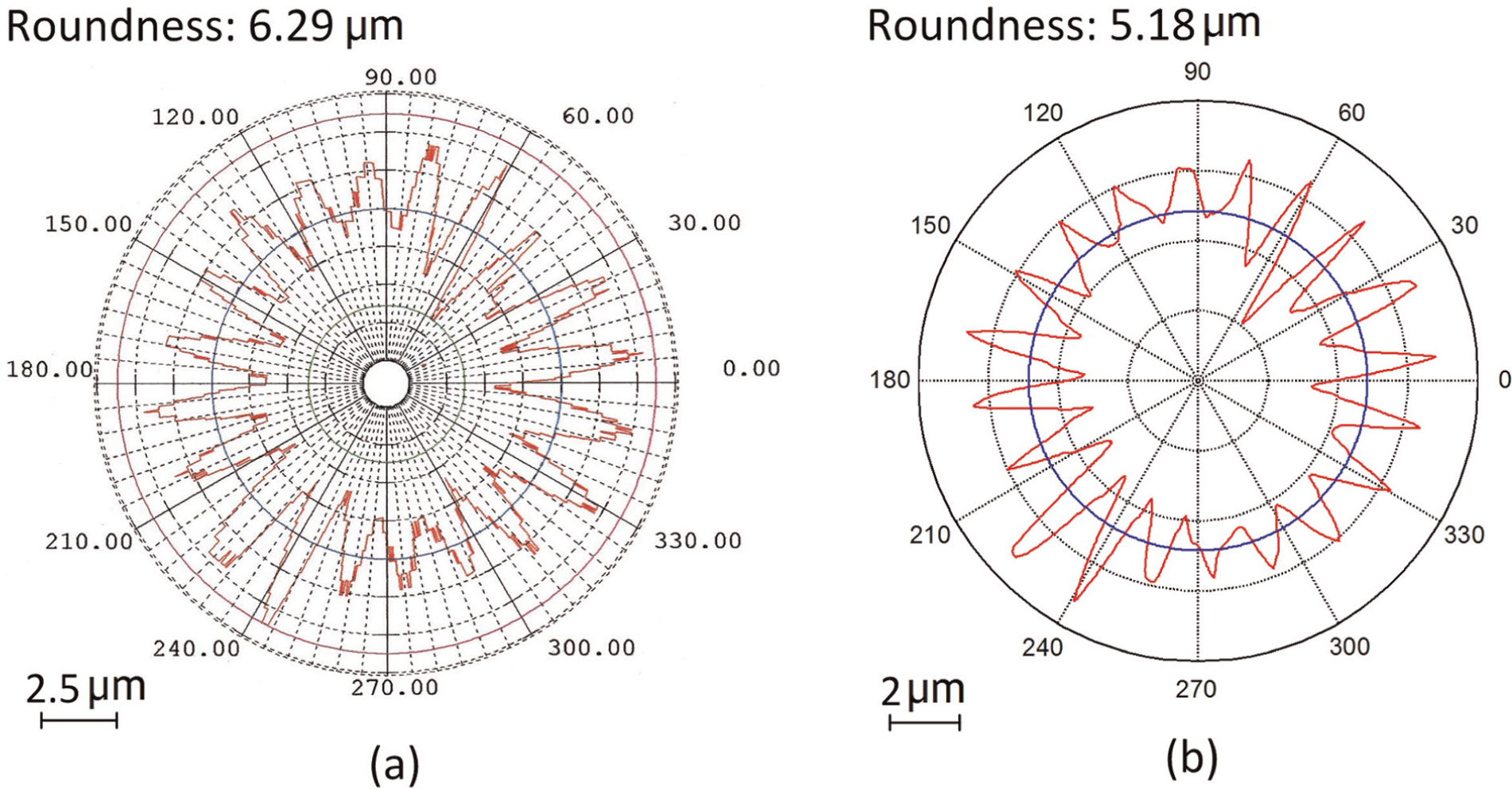
Workpiece profiles for tangent angle of 6° and removal of 0.05 mm: (a) theoretical and (b) experimental.
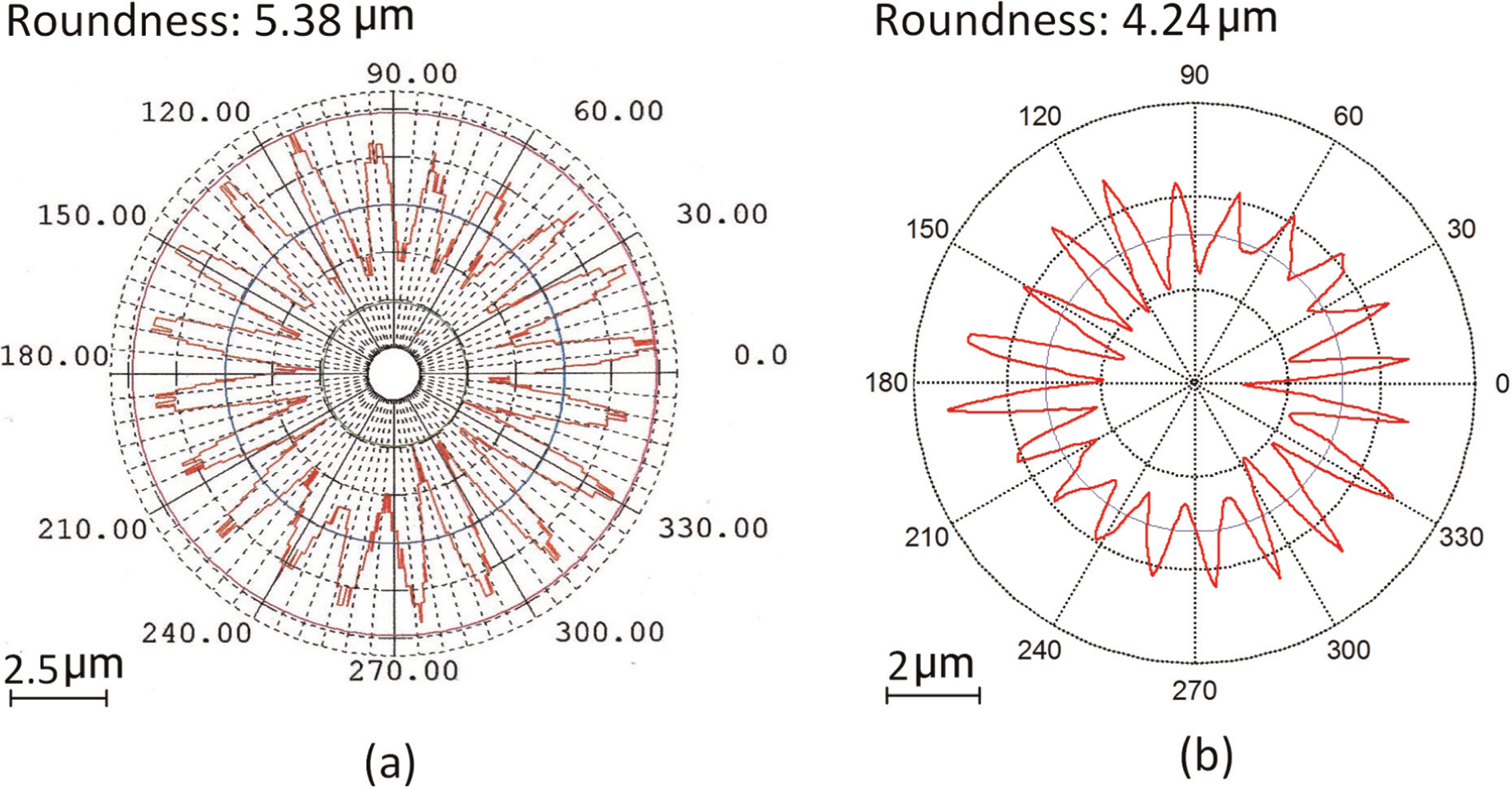
Workpiece profiles for tangent angle of 8° and removal of 0.05 mm: (a) theoretical and (b) experimental.
In Figure 9, the theoretical surface profile is similar to the measured result. The differences between them result from the initial profile errors of the wheels and the workrest. Figures 10 and 11 show the lobes of 20 dominant finished component profiles. In consideration of the condition that the lobes of 20 are geometric stable, the errors are probably produced by the vibrations of the grinding system. Overall, the predicted workpiece profile shows good correlation with the result obtained experimentally in both shape and magnitude of errors. This demonstrates the validity of the model.
Simulation-based strategies for workpiece roundness perfection
The improvement of the roundness depends on a lot of factors including proper rounding geometry, dressing precision, rotational accuracy of the wheels, the machine dynamic and the processing parameters, and they perform different effects on roundness generation. The machine set-up and the dressing parameters can be readjusted, according to the analysis of the workpiece shape. The processing parameters influence the roundness accuracy in different ways. With a compliant system and proper configuration, the magnitude of the roundness errors due to in-feed motion is extremely small. 17 Continuous workpiece speed variation (CWSV) can be used for chatter avoidance and surface finish and dimensional tolerances’ improvement. 18 Higher grinding speed will reduce the equivalent chip thickness, 19 and therefore, the grinding forces and the deformation of the system can decrease. But under higher operation speed, more severe vibration may be experienced and certain lobes will grow rapidly.
The stiffness of the elements in force loop shows significant influences on the workpiece roundness generation. 17 The errors resulting from manufacturing and assembling affect the stiffness of the bearings and they mostly determine the stiffness of the spindles. The static stiffness of the machine/grinding system shows the high correlation coefficient value with dynamic stability. 5 The apparent grinding stiffness is

where
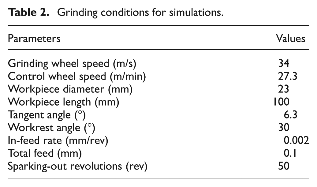
In this research, the final roundness errors under a series of the ratio of the stiffness (
Grinding conditions for simulations.
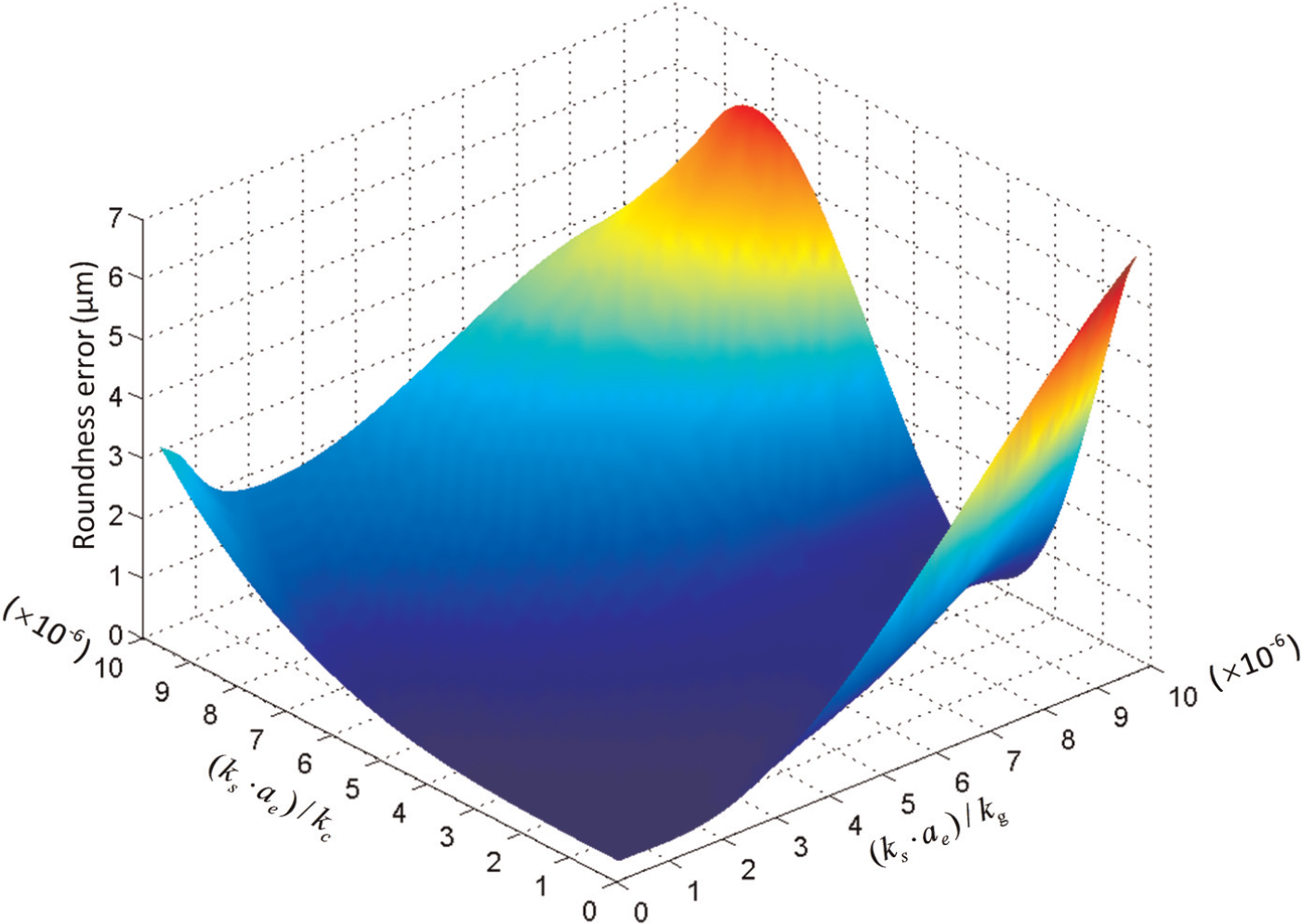
Workpiece roundness generation under various stiffness ratios.
The roundness generation figure shows that less than 0.1 µm roundness can be achieved when the ratios of both
The workpiece profiles with the variation of the stiffness ratios are simulated within the simulation system developed by the authors, as illustrated in Figure 13. The evolution of the profiles under different stiffness ratios can be observed clearly. For the higher stiffness ratios of
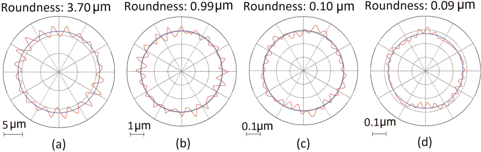
Theoretical profiles of the workpieces under stiffness ratios of (a) 10, (b) 5, (c) 1 and (d) 0.33.
Conclusion
In this article, an industrial feasible scientific approach is presented for the workpiece roundness generation and its perfection strategies in CNC centreless grinding, which is essentially important towards achieving 0.1 µm scale roundness accuracy in centreless grinding through a predictable, producible and highly productive scientific manner. The approach focuses on the workpiece kinematics and dynamics motion in its roundness generation process, which is investigated through modelling, simulation and evaluation and validation with grinding trials, and enhanced by further discussions on the workpiece roundness perfection strategies. The conclusions can be drawn specifically as follows:
Under certain grinding machine set-ups, the workpiece geometric movements due to the roundness defect were presented. By incorporating the geometric motion, the workpiece dynamics model was developed to represent the movements of the workpiece, grinding wheel and control wheel. This model can be used to analyse the workpiece rounding process and predict its roundness errors.
The workpiece roundness errors obtained theoretically were shown in good agreement with the experimental grinding trial results. The model predicts the workpiece roundness evolution in time domain accurately.
Based on the workpiece roundness generation model, the significance of the spindle bearing stiffness on the machine was investigated. The results demonstrate that the workpiece roundness at 0.1 µm scale can be achievable when both the
Footnotes
Appendix 1
Acknowledgements
The authors would like to thank Xianfeng Machine Tools Ltd for providing the CNC centreless grinding machine and support in grinding trials for this research.
Declaration of conflicting interests
The authors declare that there is no conflict of interest.
Funding
This research received no specific grant from any funding agency in the public, commercial or not-for-profit sectors.