
Abstract
In recent years, various reasons for improvement of performance and efficiency in ultrasonic vibration–assisted machining processes have been reported, which were mostly descriptive and without sufficient analytical and empirical proofs. Among the different machining processes, the least amount of experimental data and analytical relations exist about ultrasonic-assisted milling. In this article, for the first time in ultrasonic-assisted milling, we have determined the times of tool–workpiece engagement and their separation from each other in each vibration cycle and then investigated the influence of vibration amplitude and cutting speed on tool–workpiece effective engagement in ultrasonic-assisted milling. Contrary to ultrasonic-assisted turning, cutting time in each vibration cycle in ultrasonic-assisted milling is different from each other. With the aid of comprehensive experiments at tool–workpiece engagement angles smaller than 90°, we have proved that the main reason for average cutting force decrease in ultrasonic-assisted milling compared with conventional milling is the separation of tool and workpiece that occurs in a portion of each vibration cycle, and other factors such as change of friction behavior have less importance. At investigated tool–workpiece engagement angles, experimental and analytical results agree with each other.
Introduction
In recent decades, applying ultrasonic vibrations to drilling, grinding, and especially turning has been researched extensively, 1 and some advantages such as lower cutting forces 2 and probable lower risks of thermal damage even for working under dry conditions 3 have been reported for them. Zhou et al. 4 experimentally showed that compared with conventional turning (CT), the cutting performance, in terms of cutting force, surface finish, and tool life, was improved by applying ultrasonic vibration to the cutting tool.
Few studies in the field of ultrasonic-assisted milling (UAM) have been carried out in recent years. For example, Chern and Chang 5 investigated the effects of two-dimensional ultrasonic-assisted vibration cutting on the micro-milling quality of aluminum alloy Al6061-T6. They found that slot oversize, displacement of slot center, and slot surface roughness were improved, and the tool life was extended due to better machining conditions and a reduction in cutting forces. Ding et al. 6 presented a three-dimensional cutting force model of two-dimensional vibration-assisted micro-end-milling. The estimated cutting forces had a reasonable agreement with the experimental data. Shen et al. 7 investigated the effects of assisted ultrasonic vibration on the surface roughness of machined surfaces in micro-end-milling. According to the experimental results, ultrasonic vibration makes a brilliant contribution to the improvement of the surface roughness of vertical side wall surface of slot.
The fundamental basis of vibration-assisted machining processes is that the tool and the workpiece separate from each other in a portion of each vibration cycle. 8 At the instant of separation, the force exerted on the tool can be ignored. 9 The time span between tool–workpiece engagement and their separation from each other in one vibration cycle is called cutting time (tc ), and its calculation is an essential prerequisite for cutting force modeling in ultrasonic vibration–assisted machining processes. Contrary to ultrasonic-assisted turning (UAT), 10 cutting time in each of the vibration cycles in UAM, because of cutting tool revolutions, is different from each other, and its accurate determination requires further investigation.
In this study, for the first time in UAM, the times of tool–workpiece engagement and separation in each vibration cycle have been determined and then the effective engagement of tool and workpiece in different values of cutting and vibration parameters has been obtained. To investigate the influence of cutting speed, feed rate, radial depth of cut, and vibration amplitude on the amount of average cutting force reduction in UAM compared with conventional milling (CM), a full factorial design of experiments is used.
Analytical relations
The method for determination of zones, in which the tool and workpiece separation in UAM occurs, has been previously presented by Abootorabi Zarchi et al. 11 When it was determined that the tool–workpiece separation in a particular angular position of their engagement in UAM occurs, the important problem is the calculation of the times of tool–workpiece engagement (t 1) and their separation (t 2) in each vibration cycle.
Assuming that ultrasonic vibrations are applied to the workpiece, the motion of workpiece in vibration direction (x direction) can be written as

where a and f are vibration amplitude and frequency, respectively, and ω is angular frequency. Figure 1 illustrates the workpiece vibration motion and the times t 1 and t 2 in two successive vibration cycles in UAM. Cutting occurs in arcs ab, a′b′, and so on
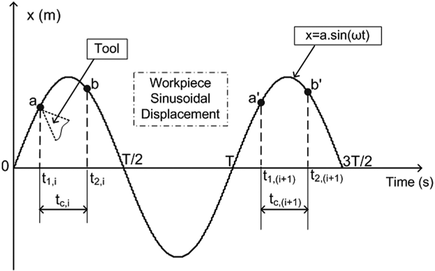
Vibration motion of workpiece and the times of tool–workpiece engagement and separation in two successive vibration cycles in UAM.
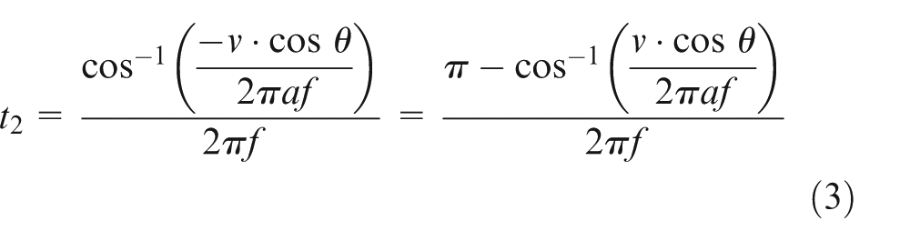
To obtain t 1 and t 2 in one vibration cycle, two conditions from process geometry should be written. The first condition is that at instant t 2, the values of tool and workpiece speeds in vibration direction are equal and unidirectional; therefore, at t = t 2

where v = πDn is cutting speed and D and n are end mill diameter and its number of revolutions, respectively. The vibration of the workpiece is in the direction of the feed motion. Since the feed speed of milling machine table is small in comparison with cutting speed of tool and vibration speed of workpiece, in writing analytical relations, the feed rate is ignored. Now, two cases arises:
Case 1: if
Case 2: if

To obtain t 1, based on Figure 1, the second geometric condition should be written. In vibration milling, the workpiece separates from the cutting tool at t = t 2 (point b) and after traveling through a path engages again with the tool (point a′). In UAM process, if the time of tool–workpiece engagement in the ith vibration cycle is denoted t 1i , the time of their engagement in the (i + 1)th vibration cycle is slightly different from t 1i + T, where T is the cycle of the workpiece sinusoidal vibration. This fact is ignored in writing the second condition. The difference in workpiece spatial positions in points b and a′ (Figure 1) is equal to the tool displacement in this interval; therefore

To solve equation (5), four different cases arise, summarized as follows:
Case 1: if

where K 1 and K 2 are the constants and can be obtained from the following relations
Case 2: if

where K 3 is a constant and can be obtained as follows

After calculation of t 1 and t 2, cutting time in one vibration cycle can be determined from the following relation

Figure 2 shows the values of tc in each of the vibration cycles of UAM during slot milling operation with n = 500 r/min, a = 5 µm, and f = 20 kHz. In all calculations and experiments of this article, the diameter of end mill is D = 10 mm. It is obviously seen that contrary to UAT, 10 the amounts of cutting time in each vibration cycle are different from each other.
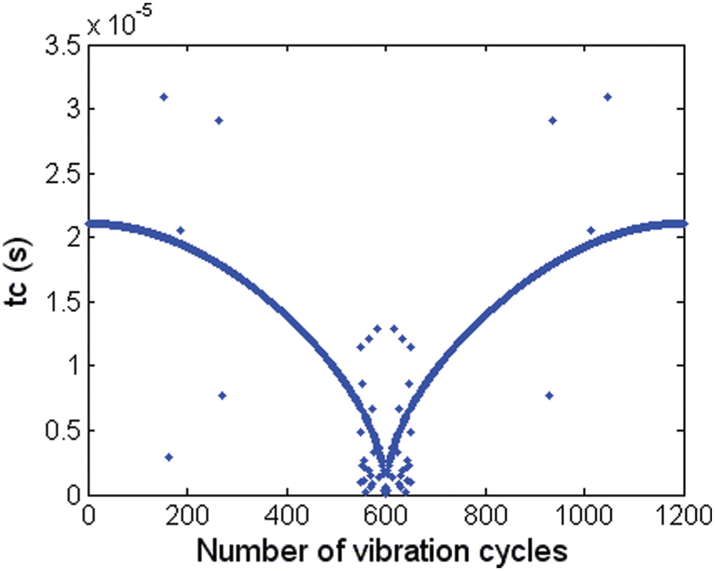
Variations of cutting time in each vibration cycle of UAM during slot milling with n = 500 r/min, a = 5 µm, and f = 20 kHz.
Here, a new parameter called “engagement percent” (E(%)) is defined. End-milling process is shown schematically in Figure 3. φst and φex are the angular positions of the beginning and the end contact of tool and workpiece, respectively.
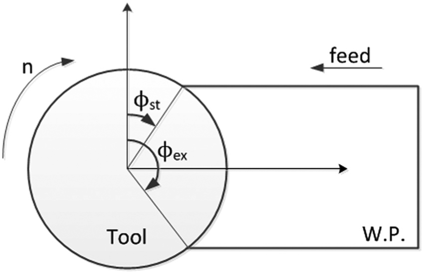
Schematic diagram of the end-milling process.
E(%) in UAM is defined as the ratio of the sum of cutting time values in each vibration cycle which takes place within time span corresponding to distance between φst and φex , to the total required time for cutting edge movement from φst to φex , as follows

where tc , i is cutting time in the ith vibration cycle, Te is the time required for cutting edge movement from φst to φex , and k is the number of workpiece vibration cycles in the time span in which cutting edge moves from φst to φex and is obtained by the following equation

In Figure 2, since n = 500 r/min, the required time for a half revolution of the tool is Te
= 0.06 s. Due to the vibration frequency f = 20 kHz, the workpiece vibrates 1200 times during 0.06 s, and thus, k = 1200. In the 600th vibration cycle, the tool and workpiece engagement angle is θ = 90°. According to equation (3),
Figure 4 shows the relation between the E(%) and the vibration amplitude during slot milling by ultrasonic assistance with constant parameters n = 2500 r/min and f = 23,456 Hz. In slot milling, φst = 0° and φex = 180°. It can be observed that with the increase in vibration amplitude, the amount of E(%) reduces.
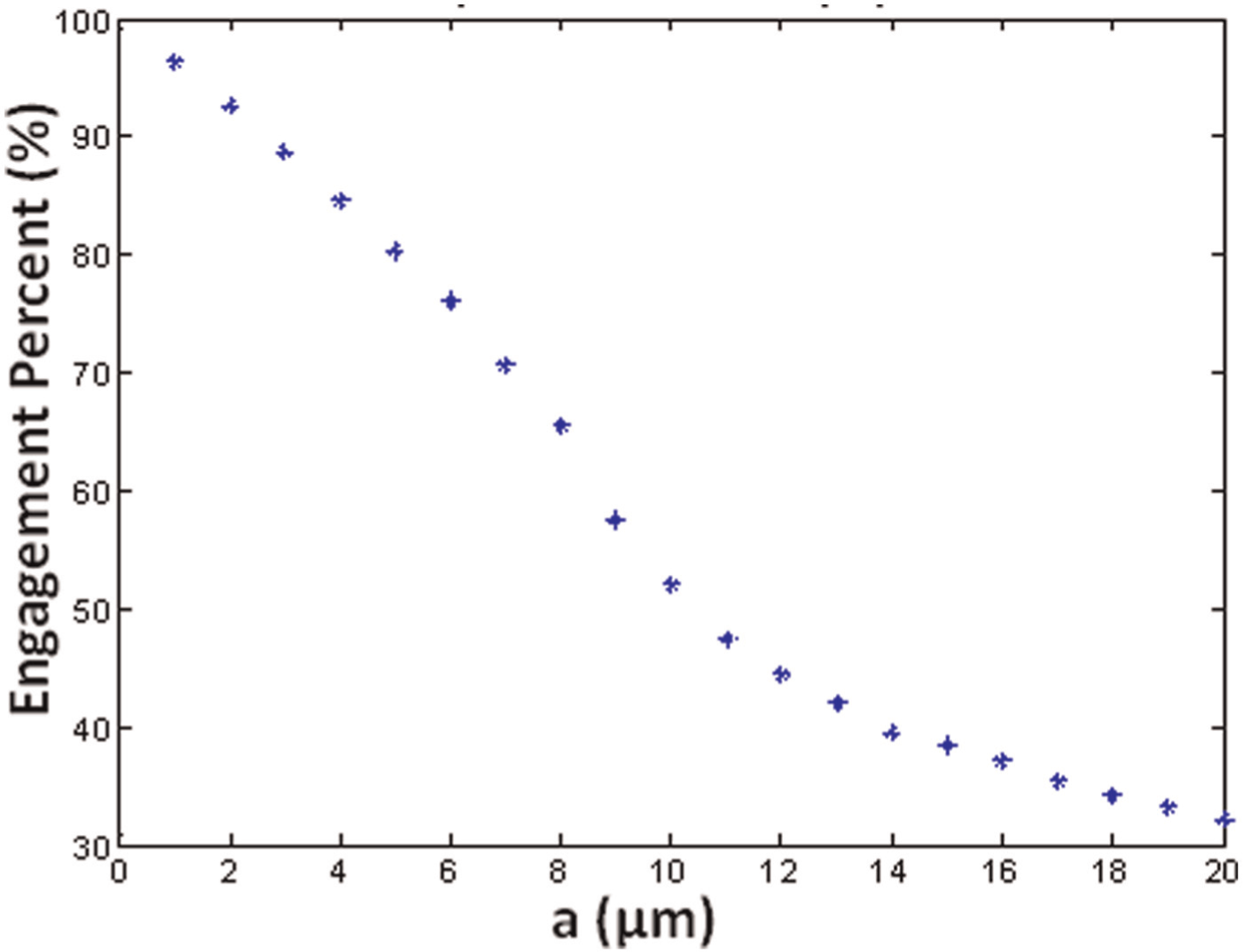
Relation between the engagement percent and the vibration amplitude during slot milling by ultrasonic assistance with constant parameters n = 2500 r/min and f = 23,456 Hz.
Figure 5 illustrates variations of the E(%) versus the spindle speed in ultrasonic-assisted slot milling operation. Constants used in Figure 5 are a = 5 µm and f = 23,456 Hz. The increase in spindle speed (or cutting speed) increases E(%). It should be mentioned that the observed trends in Figures 4 and 5 exist in other cutting and vibration conditions.
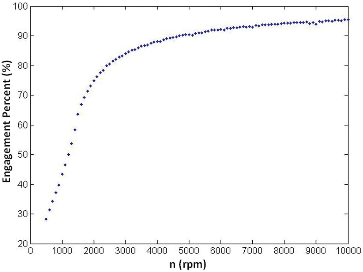
Variation in the engagement percent versus spindle speed in ultrasonic-assisted slot milling with constant parameters a = 5 µm and f = 23,456 Hz.
Experimental setup
The experimental setup is shown schematically in Figure 6(a). For measuring maximum vibration amplitude at workpiece end part, a gap sensor, a converter, and one oscilloscope have been used. With switching off the ultrasonic power supply, CM tests have been also done by the same equipment. The experimental setup is shown in Figure 6(b).
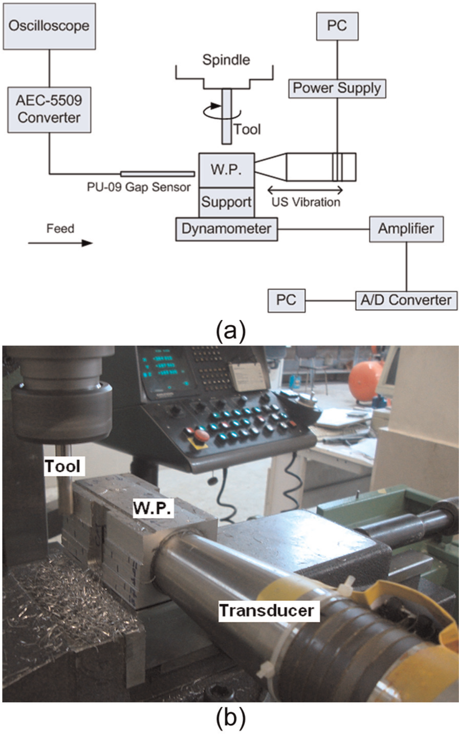
(a) Scheme of the experimental setup and (b) experimental setup for CM and UAM tests.
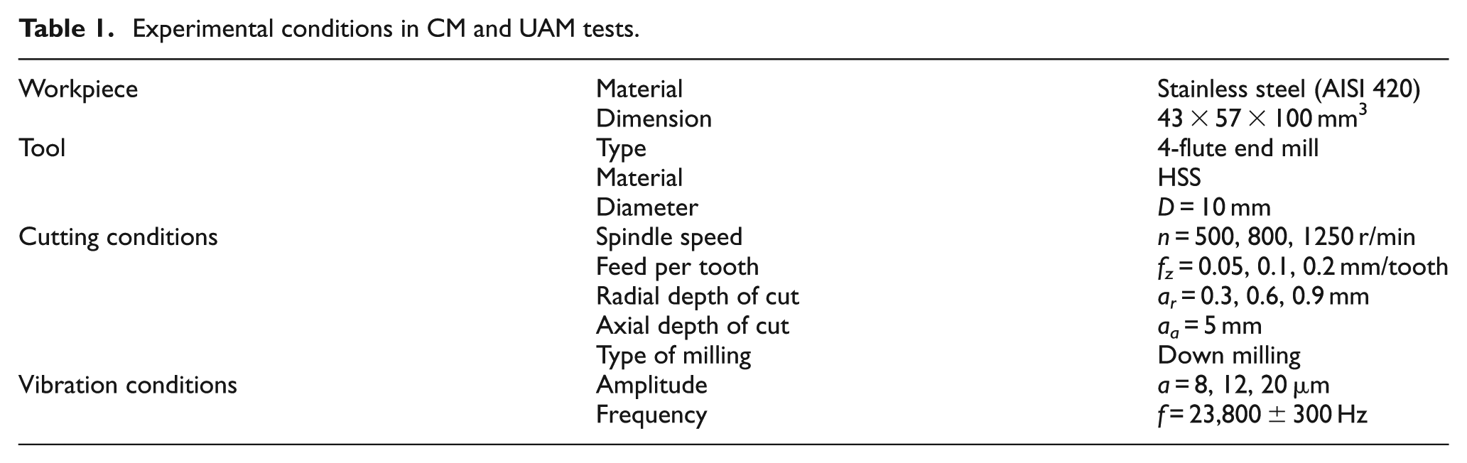
In order to investigate the influence of ultrasonic vibrations on cutting forces in milling process, comparative experiments have been carried out. The experimental conditions are summarized in Table 1. Design of experiments was full factorial, and on the whole, 81 experiments were done.
Experimental conditions in CM and UAM tests.
Experimental results and discussion
In order to have similar test conditions, in each experiment, CM and UAM processes have been performed consecutively and without stopping the feed movement of milling machine table and the rotational motion of spindle. A sample of recorded normal and feed forces by a 9255B KISTLER dynamometer is shown in Figure 7 in which n = 500 r/min, feed per tooth fz = 0.2 mm/tooth, radial depth of cut ar = 0.9 mm, and a = 20 µm. Decrease in normal and feed cutting forces in UAM compared with CM can be obviously seen in Figure 7. The dimensions of the workpiece were determined by finite element analysis such that during the tests, a longitudinal standing wave was created along the workpiece length with two loops at the ends and a vibration node at the center. To prevent waste of vibrations, the workpiece was held by a steel support by two M8 bolts and two 8-mm-diameter pins at its vibration node. Moving from the end to the mid-section of the workpiece, the amount of vibration amplitude changes from maximum to 0. In Figure 7, the increase in the cutting force in the UAM process is due to the decrease in the vibration amplitude.
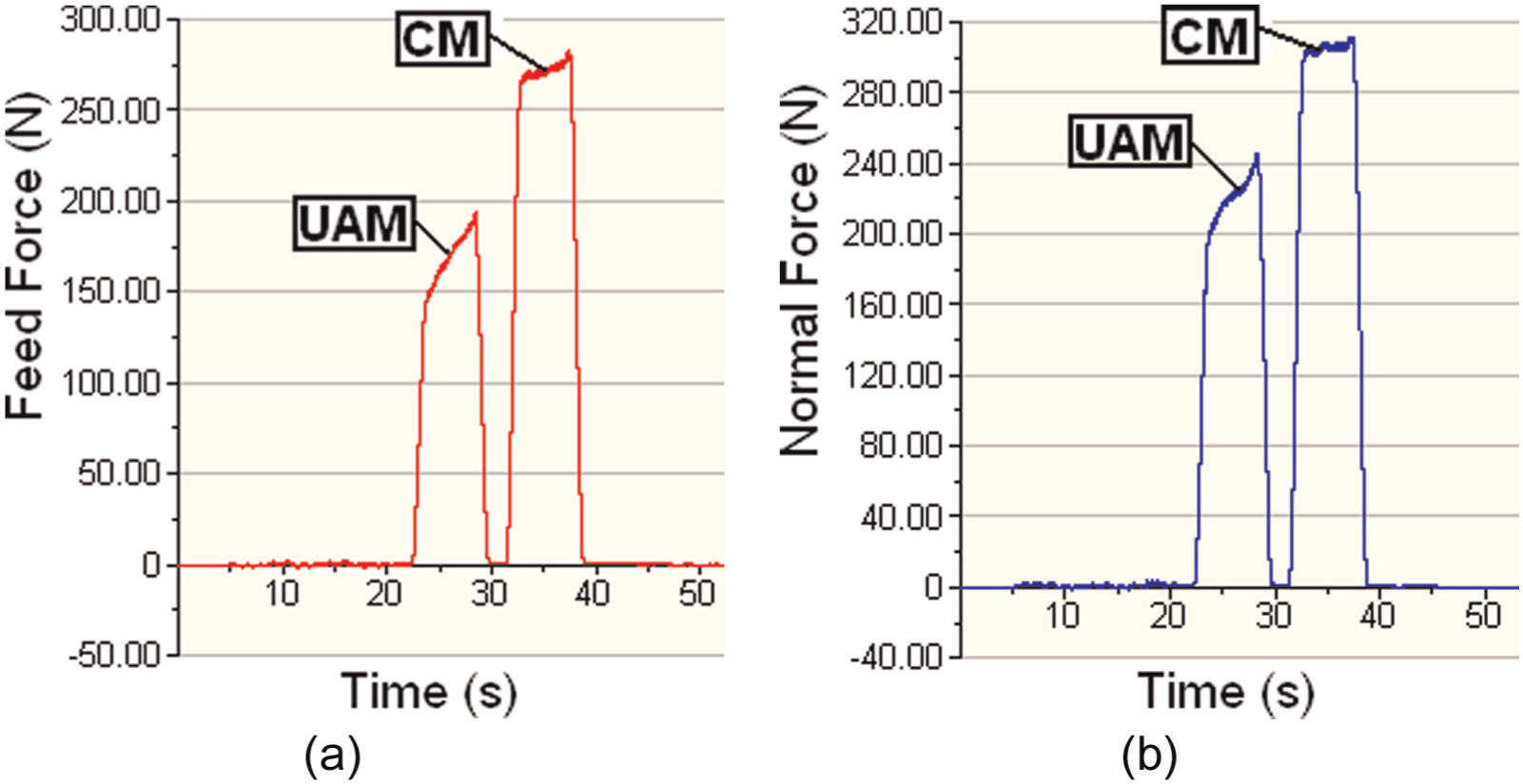
Cutting force in (a) feed and (b) normal directions in CM and UAM with n = 500 r/min, fz = 0.2 mm/tooth, ar = 0.9 mm, and a = 20 µm.
As the workpiece is vibrating with a frequency of f ≈ 24 kHz, the dynamometer must be capable of measuring the changes in the cutting force at each vibration cycle with a rate of at least 48,000 times per second to be able to capture the actual cutting force behavior without aliasing (Nyquist theorem). This high-frequency response is out of reach with existing mechanical systems. The resonant frequency of 9255B dynamometer is less than 3 kHz. Due to this limitation, the average values of cutting force in UAM have been compared to the average cutting force values in CM.
The percentage of average cutting force reduction in UAM to CM versus the vibration amplitude is shown in Figure 8. In comparison to CM, the amounts of average cutting forces in UAM are smaller, and with increase in vibration amplitude, the degree of cutting force reduction is more noticeable.
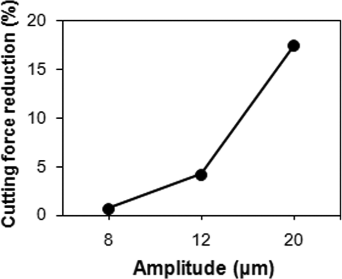
Percentage of average cutting force reduction in UAM to CM versus the vibration amplitude.
According to literature review, the reason for cutting force reduction in vibration-assisted cutting processes compared with conventional processes is attributed to two factors: first, separation of the tool and the workpiece in a portion of each vibration cycle which leads to decrease in average cutting force;8,10 and, second, change of friction behavior in vibration processes. Chou 12 said that friction force in UAT is less than in CT, but recently Jamshidi and Nategh 13 with theoretical and experimental investigation of the friction behavior in UAT showed that a higher coefficient of friction exists in UAT compared with CT. They found that the friction coefficient in UAT would be increased with an increase in the vibration amplitude.
Using analytical relations to calculate E(%) showed that the increase in the vibration amplitude results in the decrease in E(%) (Figure 4). Decrease in the amount of tool–workpiece engagement results to larger decrease in average cutting force. In Figure 8, with an increase in the vibration amplitude and, therefore, decrease in E(%), the average of cutting forces in UAM decreases largely compared with CM. This is in agreement with analytical findings.
The effects of fz and ar on the percentage of average cutting force reduction in UAM to CM are shown in Figure 9(a) and (b), respectively. It can be seen that feed per tooth and radial depth of cut have no meaningful influence on the amount of cutting force reduction in UAM to CM.
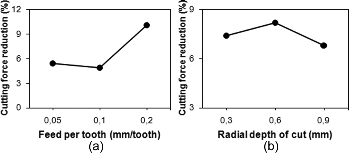
Percentage of average cutting force reduction in UAM to CM versus (a) feed per tooth and (b) radial depth of cut.
The percentage of average cutting force reduction in UAM to CM versus the spindle speed is illustrated in Figure 10. In such spindle speeds, the average cutting force in UAM is less than that in CM; however, as the spindle speed increases, the average cutting forces in CM and UAM converge.
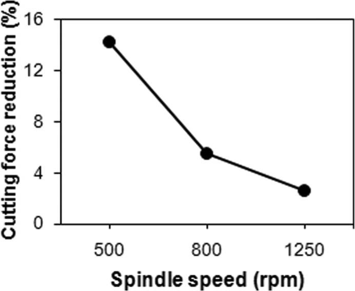
Percentage of average cutting force reduction in UAM to CM versus spindle speed.
In Figure 5, it has been analytically shown that an increase in spindle speed leads to increase in E(%) which itself results in approaching UAM to CM. Experimental observations (Figure 10) are again in agreement with analytical findings (Figure 5).
Conclusion
In this study, for the first time in UAM, a model for calculating the instants of tool–workpiece engagement and their separation in each vibration cycle was derived and then cutting time and tool–workpiece E(%) were obtained. The results have been verified by experiments. The following conclusions can be drawn from this study:
Contrary to UAT, cutting time in each vibration cycle of UAM is different from each other;
The average of experimental cutting forces in UAM is less than in CM;
An increase in the vibration amplitude leads to a decrease in E(%) which itself results in larger reduction in cutting force in UAM compared to CM;
An increase in cutting speed leads to increase in E(%) which itself results in increase in cutting forces in UAM and approaching UAM to CM;
The main reason for cutting force reduction in UAM compared with CM is the decrease in the degree of tool–workpiece engagement due to imposed ultrasonic vibrations. Experimental results are in good agreement with analytical findings.
Footnotes
Appendix 1
Declaration of conflicting interests
The authors declare that there is no conflict of interest.
Funding
This research received no specific grant from any funding agency in the public, commercial, or not-for-profit sectors.