
Abstract
Based on the modeling of circular corner milling process, the implicit three-step four-order ADAMS numerical analysis method is presented in this article to solve the differential equation of milling dynamics, which considers non-uniform variation of the radial depth of cut and nonlinear feature of tool–workpiece system. The dynamic cutting forces are predicted in time domain and experimentally verified. On this basis, with comprehensive application of time-domain stability criteria for predicted data, the chatter stability of the milling process is simulated. The predicted stability lobe diagrams are compared against experimental results to confirm the validity of the simulation algorithm, which provides an effective way to optimize cutting parameters for circular corner milling.
Introduction
With the high increasing requirements on productivity and quality of modern manufacturing processes, milling operation has been widely used in aerospace, automotive, mold and other machinery industries. However, problems of circular corner milling in manufacture are prominent as the continuously changing engagement state of the tool and the workpiece leads to time-varying chip thickness and cutting forces direction. In addition, with over-cutting and undercutting, chatter instability is easy to be triggered if the process parameters, such as the depth of cut, the spindle speed and the step over feed, are selected improperly, and it seriously restricts the processing efficiency, has an adverse effect on surface quality of the workpiece and shortens the tool’s lifetime or even destroys the tool or the machine tool. Many researches have thus been devoted to describing the chatter of the material removal processes. Yoon and Chin 1 presented a new method for the detection of chatter in the end-milling operation based on the wavelet transform. This wavelet transform method provides various ways to determine chatter characteristics. Tsai et al., 2 proposed an innovative control loop based on the spindle speed compensation strategy (SSCS) using the acoustic chatter signal index (ACSI) to prevent the occurrence of milling chatter. Polli et al. 3 analyzed the dynamic stability of the high-speed end-milling process; evaluated stability based on sound pressure, machining force and tool displacement measured during the process and proposed a new method to investigate the transition from stable cutting to cutting with chatter.
Especially, there are also many researchers who focus on the cutting forces prediction for circular corner milling. Kardes and Altintas 4 realized the prediction of time-varying cutting forces and chatter stability using a mathematical model of chip removal mechanism. Nonetheless, their research object is confined to the circular path rather than the typical circular corner milling. Zhongqun and Qiang 5 proposed a time-domain model to predict the cutting forces of circular corner milling. For theoretical prediction of milling chatter stability, the first approach was presented by Tobias and Fishwick 6 and Tlusty and Polacek 7 who identified the regeneration mechanism and developed mathematical models in the form of delay differential equations (DDEs). Altintas and Budak 8 presented an analysis method using a Fourier series-based method for handling the time-dependent directional dynamic milling force coefficients, which has been extensively verified by experiments,8–11 and applied to the stability analysis of ball end milling and three-dimensional (3D) milling. Zhongqun and Qiang12,13 performed a simulation method to systematically analyze the effects of modal parameters on chatter stability, developed some concepts of peak to valley ratio and lobes coefficient and advanced the universal principle of modal simplified in multi-modal system. Besides, based on the typical analysis method, they proposed an effective way that can quickly construct the chatter stability lobes by directly using the frequency response function of the tool-tip point. However, as the cutter travels around the circular path, the radial depth of cut, and the intersection of the tool and the workpiece may change continuously. Moreover, the cutter may disengage from the cutting zone due to excessive vibration. Accordingly, it is unable to obtain the precise chatter stability of through the frequency domain analysis method.
Therefore, confronted with circular corner milling, this article attempts to establish the relatively realistic kinematics and dynamics model for the cutting process, and research on the prediction of cutting forces and chatter stability by time-domain numerical analysis method. Accompanied by experimental verification, it provides guidance for the selection and optimization of machining parameters in theory.
Dynamic process modeling for circular corner milling
Zhongqun 14 discussed the modeling of typical circular corner milling process in detail. Compared with linear milling process, the cutting forces of circular corner milling are in constant change because of time-varying chip thickness when the cutter travels along the circular tool path. So the circular corner milling process should be discretized with the time step of dt, which is in order to calculate the instantaneous cutting forces at each time step.
As the stiffness of the machine–tool system in Z direction is much larger than that in lateral direction (namely X and Y directions), chatter is prone to occur in these two directions. So considering the cutting deformation of the cutter or workpiece, the milling process with the cutter can be simplified to a 2-degrees of freedom (DOFs) vibration system in two lateral directions. 15 Then, the dynamic differential equation was shown as follows
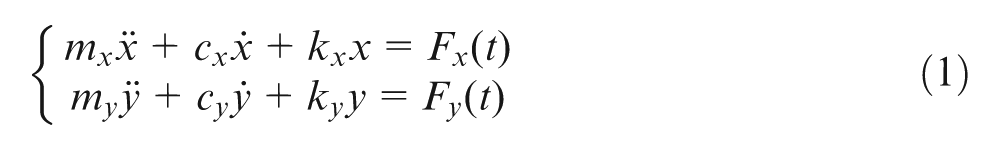
where mx, cx, kx and my, cy, ky represent modal mass, damping and stiffness of machine–tool system in the X and Y directions, respectively.
Referring to the geometrical modeling for the cutting edges of a cylindrical end mill, 16 it is assumed that the tool parameters are composed of teeth number N, helix angle β and radius R, and the cutting variables include the spindle speed n, the axial depth of cut ap, the radial depth of cut ae and the feedrate per tooth ft. When the cutter is divided into M small disk elements with an infinitesimal axial depth of dz along the axial direction, the instantaneous immersion angle Φkjl for element l of tooth j at kth time step can be expressed as

where ω is the spindle angular velocity and ω = 2πv/60.
Then, the dynamic un-deformed chip thickness can be defined as
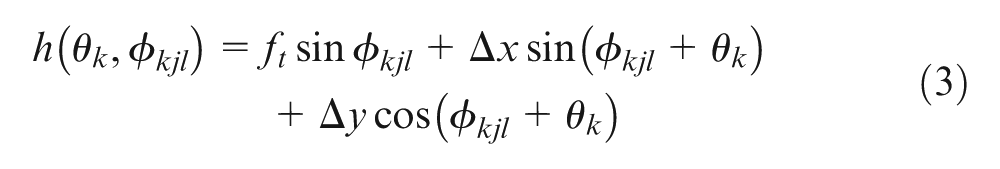
where Δx and Δy are the dynamic displacements between the cutter and the workpiece in the X and Y directions, respectively, and Δx = xk−xk−1, Δy = yk−yk−1.
As shown in Figure 1, θk is the traversed angle of the tool center around the tool path which changes continuously along the circular tool path. The detailed calculation of θk can be found in literature. 5
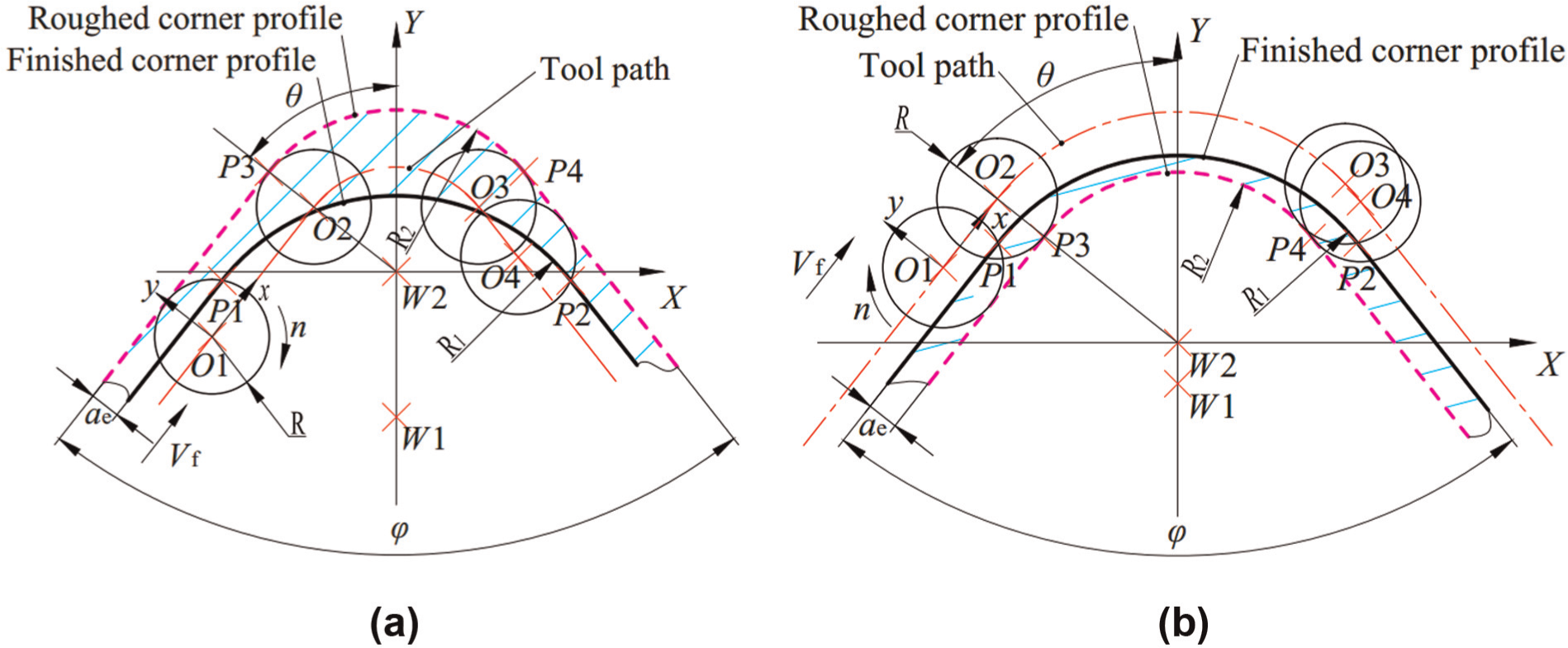
Geometrical model of the circular corner milling: (a) inner conner milling and (b) outer conner milling. R1 is the radius of the finished circular profile, R2 is the radius of the roughed circular profile, φ is the inclined angle of the two lines of the tool path and ae is the initial radial depth of cut before the cutter enters the corner.
According to the basic formula for instantaneous rigid force model, 16 the differential tangential dFtkjl and the radial dFrkjl cutting forces acting on the element l of tooth j at kth time step can be given as
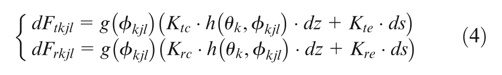
where ds is the infinitesimal length of cutting edge and ds = dz/cosβ. Ktc, Krc, and Kte, Kre represent the tangential and radial specific cutting forces and edge force coefficients, respectively, and their specific values can be obtained by means of a cutting force coefficients identification test. g(Φkjl) is used in order to define whether element l of tooth j at kth time step is in cut or not. When Φst≤g(Φkjl) ≤Φex, the element is in cut and g(Φkjl) = 1 or g(Φkjl) = 0.
Here, Φst and Φex are the entry angle and exit angle, respectively, of the cutter during the milling process, which can be calculated at each time step. 5
Through coordinate transformation, the numerical integration along the axis direction and the summation of each cutting force, the instantaneous dynamic cutting forces acting on the cutter in the X and Y directions at the kth time step can be projected as follows
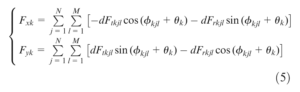
And the instantaneous dynamic cutting forces attained by the above equation (5) can be used into the differential equation (1) to solve the instantaneous dynamic displacements xk and yk.
Time-domain simulation of dynamic cutting forces
According to the dynamic process modeling for circular corner milling, the key problem is how to solve the milling dynamics differential equation (1). Since it is unable to represent exciting forces with simple expressions, the equation cannot be directly integrated in closed form. Therefore, this article proposes the implicit three-step four-order ADAMS numerical analysis method to solve the milling dynamics differential equations presented above. Because the calculated result of instantaneous dynamics cutting forces will be used to achieve the chatter stability lobes diagram in section “Time-domain simulation of chatter stability” of this article, high accuracy of the result is crucial and should be obtained as far as possible. Compared to traditional single-step methods such as Euler method, improved Euler method, Runge–Kutta method and so on, this method makes full use of the existing information, it owns better stability, convergence and higher solution accuracy, which can fulfill the requirement of simulation. 17
For the differential equation in the X direction, define
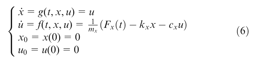
The corresponding ADAMS interpolation format is as follows
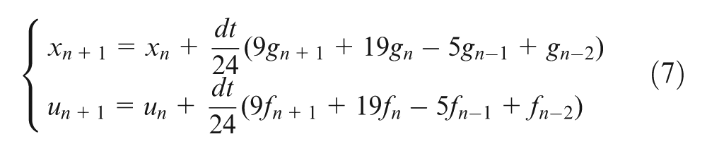
In order to obtain satisfactory accuracy, while reduce the computing time, dt = 1/n is selected and used.
To solve xn+1, un+1 in equation (7), the iterative method should be adopted. However, considering the large amount of calculation for implicit method, we can take corresponding explicit ADAMS method as the forecasting format, and use the implicit ADAMS method for iterative correction. Then, the ADAMS forecasting correction format is taken as
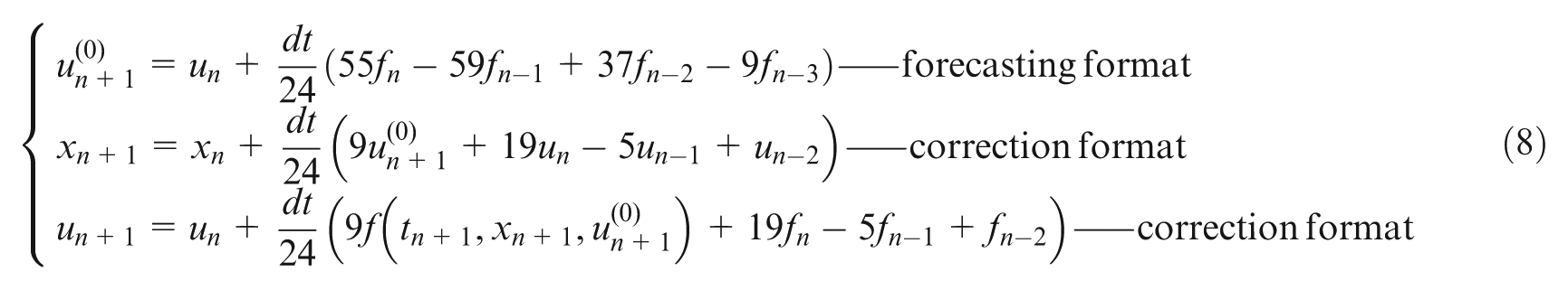
and the high-accuracy initial values x1, x2, x3 and u1, u2, u3 calculated by the following four-order Runge–Kutta formula (9) are substituted into the ADAMS forecasting correction format in equation (8). The numerical solution of the differential equation (6), namely, xn can be obtained
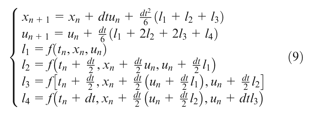
Likewise, the differential equation in Y direction can be solved.
In summary, the prediction of the time-domain instantaneous dynamic cutting forces for circular corner milling is as follows:
Starting from the given initial conditions, first determine which step of the circular milling process the cutter is in (pre-corner milling, corner milling and post-corner milling);
Calculate the traversed angle θk of the tool center around the tool path, the tool–workpiece intersection angles Φst, Φex, and the instantaneous immersion angle Φkjl for element l of tooth j at kth time step, then determine whether element l of tooth j is in cut or not;
Get the dynamic displacements of the tool and the workpiece and the dynamic un-deformed chip thickness at this very moment;
Acquire the instantaneous dynamic milling force by equation (5); then, the displacement and velocity of the cutter in the X and Y directions at next moment are solved by equation (1). This cycle continues, and the simulation result of the overall cutting forces can be obtained.
Specifically, the algorithm for prediction of instantaneous dynamic cutting forces is presented in Figure 2.
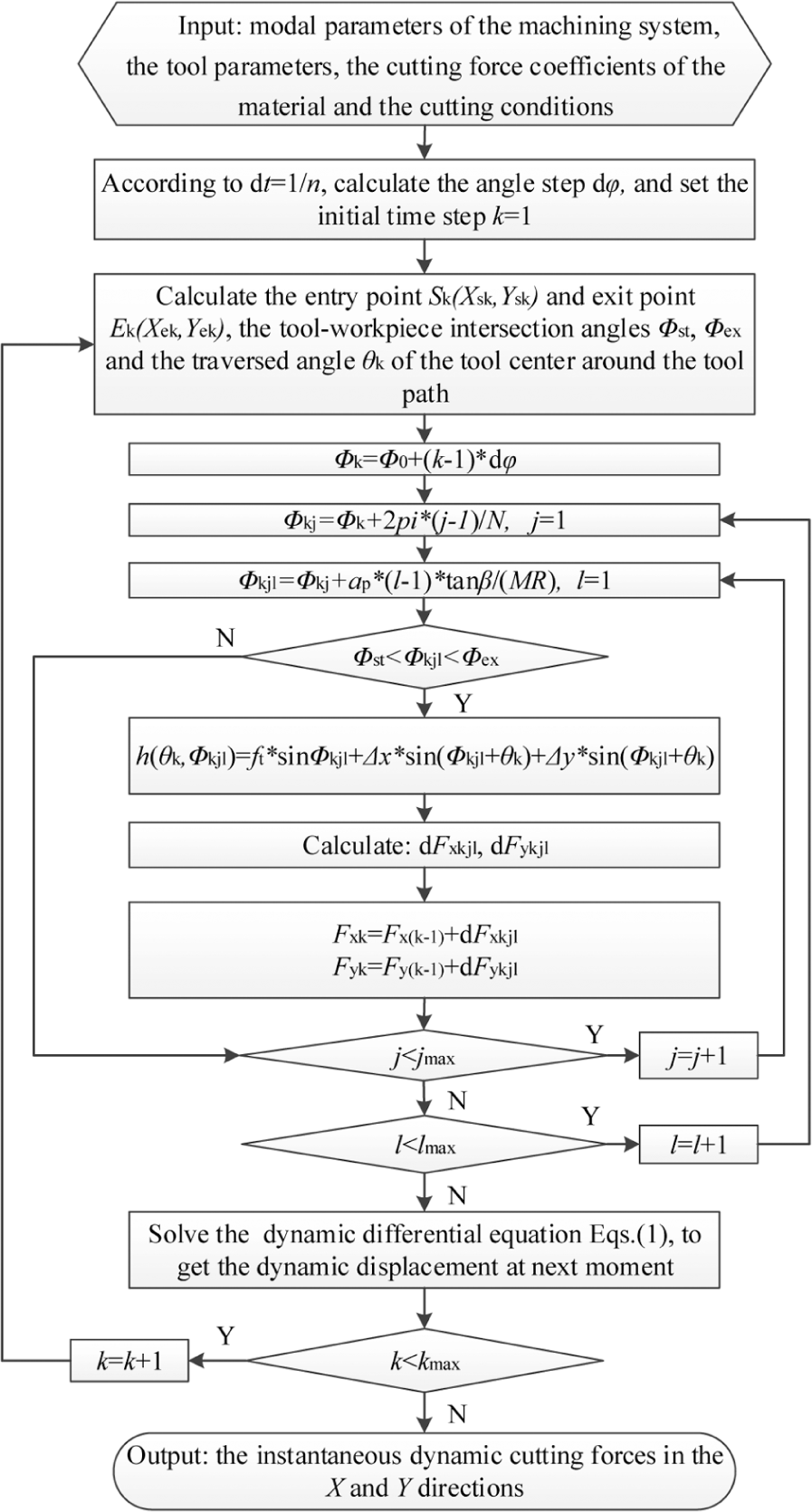
Algorithm for prediction of instantaneous dynamic cutting forces.
Time-domain simulation of chatter stability
Based on the above-mentioned time-domain simulation algorithm of dynamic cutting forces, for the corresponding cutting parameters of each spindle speed and axial depth, the chatter stability criterion is applied to determine whether the present cutting is stable or not. Then, the time-domain simulation of chatter stability for circular corner milling can be achieved. It is critical that the stability criterion for time-domain simulation data first be established among the simulation of chatter stability.
In order to obtain the reliable chatter stability lobes diagram, this article synthetically selects the Poisson tree processes (PTP) method 18 and the dynamic/static forces method 19 as the chatter criterions. Procedures to gain the chatter stability lobes diagram are given as follows:
Depending on the given cutting conditions, time-domain simulations are conducted to obtain the dynamic cutting forces and tool-tip positions.
Use the PTP method and the dynamic/static forces method, and judge whether chatter occurs or not under current cutting conditions.
Change the axial depth of cut and repeat steps (1) and (2); the critical axial depth of cut under the current spindle speed is obtained.
Change the spindle speed with a certain step size and repeat steps (1), (2) and (3), the corresponding critical axial depth for each spindle speed can be obtained. Then, the chatter stability lobes diagram can be drawn taking spindle speed as X axis and the critical axial depth as Y axis. The algorithm for simulation of chatter stability is outlined in Figure 3.
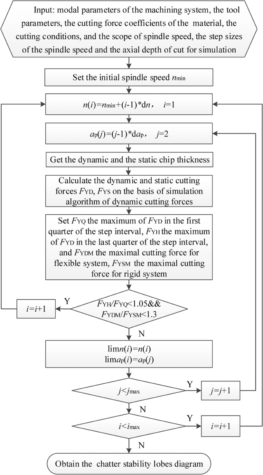
Algorithm for simulation of chatter stability.
Experiment verification and discussion
Cutting forces and chatter verification tests for circular corner milling have been performed on a vertical machining center VMC0656mu. The maximum spindle speed of the machine is 24,000 r/min. A two-fluted carbide end mill with 30° helix angle, 12 mm diameter and 36 mm overhanged length was used. The workpiece material was a 7050T74 aluminum alloy. The cutting force coefficients which were measured by an identification test 20 are given as follows: Ktc = 1039.073 N/mm2, Krc = 207.161 N/mm2, Kte = 32.977 N/mm and Kre = 61.000 N/mm.
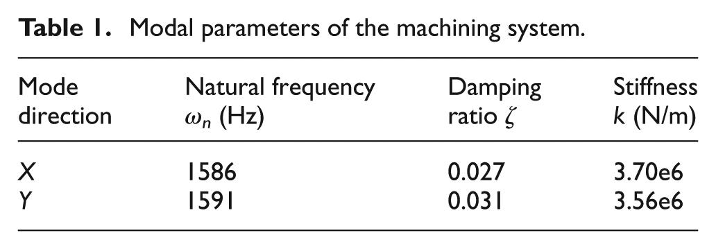
The dynamic characteristics analyzing system of machine tools Dynacut2.0 was applied in hammering test for the machine tools in the X and Y directions to obtain the corresponding modal parameters of the machining system respectively. The results are shown in Table 1.
Modal parameters of the machining system.
Dynamic cutting forces verification
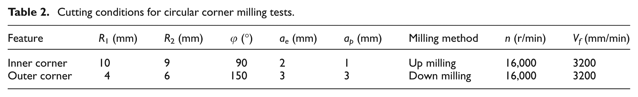
In this experiment, two different cutting conditions are conducted to verify the proposed approach of cutting forces prediction for both inner corner and outer corner milling. The cutting conditions are listed in Table 2.
Cutting conditions for circular corner milling tests.
During the circular corner milling process, the instantaneous cutting forces are measured by a Kistler dynamometer 9257B mounted between the workpiece and the workbench, and the overall configuration of the experimental set-up is shown in Figure 4. The simulated and measured results are given in Figure 5.
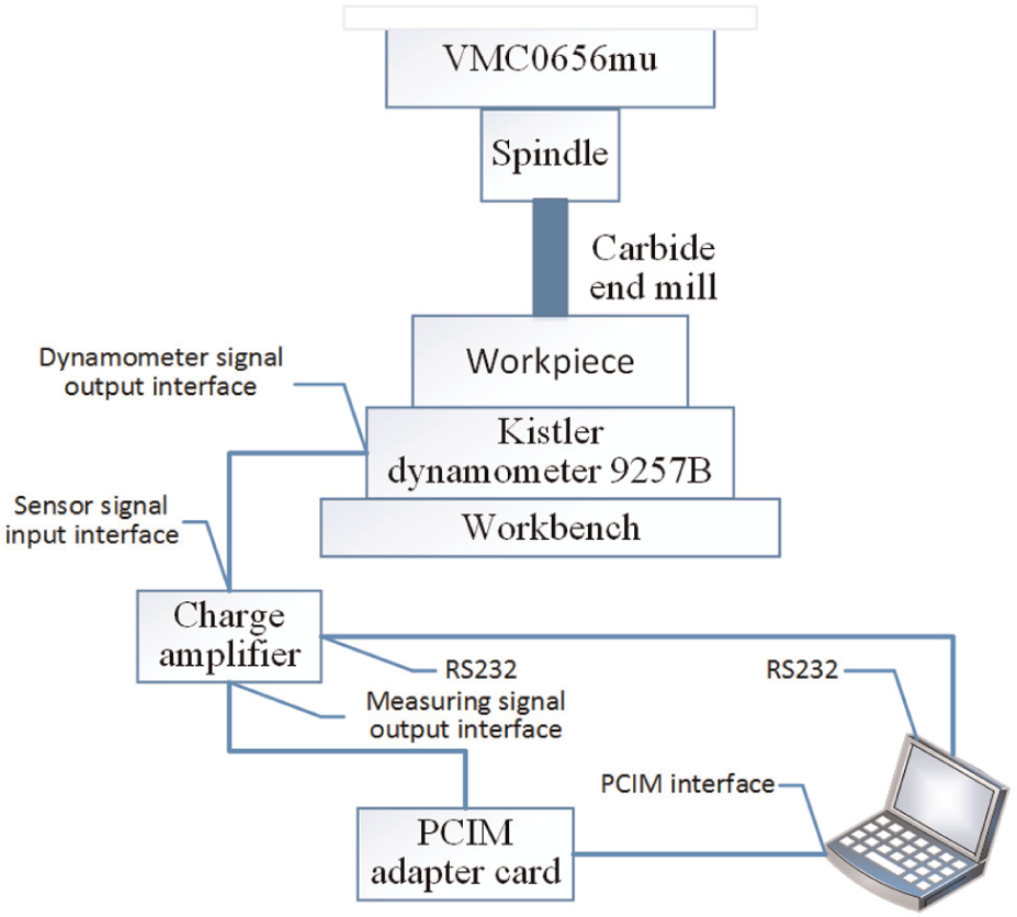
Configuration of the experimental set-up.
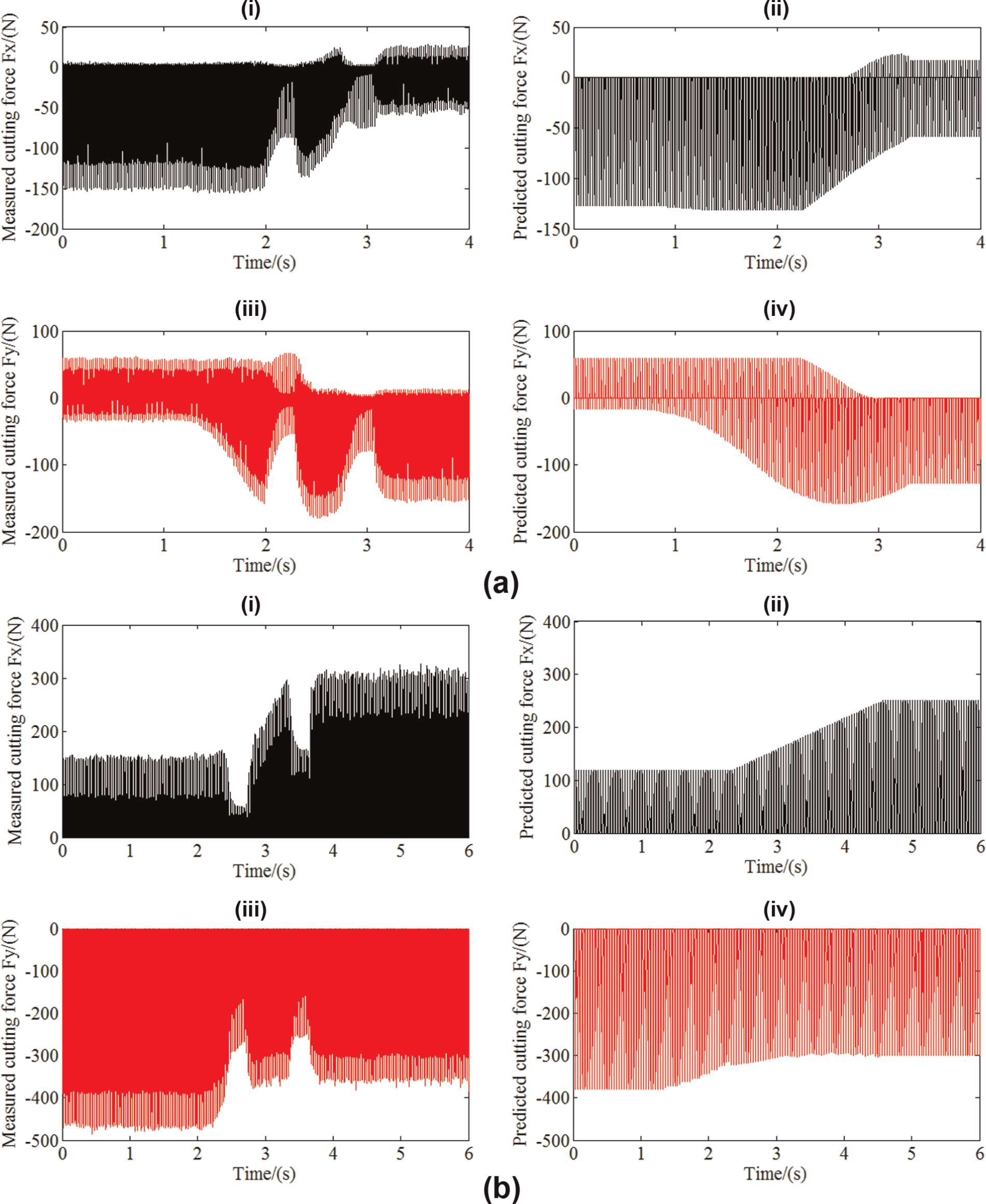
Comparisons of predicated and measured cutting forces for cutting conditions. (a) Inner corner up milling: φ = 90°, R1 = 10 mm, R2 = 9 mm, ap = 1 mm, ae = 2 mm, n = 16,000 r/min and Vf = 3200 mm/min and (b) outer corner down milling: φ = 150°, R1 = 4 mm, R2 = 6 mm, ap = 3 mm, ae = 3 mm, n = 16,000 r/min and Vf = 3200 mm/min.
Considering that the radial depth of cut increases rapidly at the corner, the feedrate will decrease when the cutter enters and leaves the corner, which will result in great decrease in force. However, with the constant feed rate in simulation, the variation of predicted cutting forces is just caused by the variation of the radial depth of cut. Consequently, as shown in Figure 5, the predicted cutting forces are in accord with the measured results.
Chatter stability verification
For the above-mentioned inner corner milling, through the given cutting conditions, the n-ap chatter stability lobes diagram which are simulated in the algorithm of chatter stability are shown as real line in Figure 6. Among them, the spindle speeds were selected from 4000 r/min to 24,000 r/min with a step size of 100 r/min, the feedrate per tooth was fixed at 0.1 mm and the step size of the axial depth of cut was set to 0.01 mm.
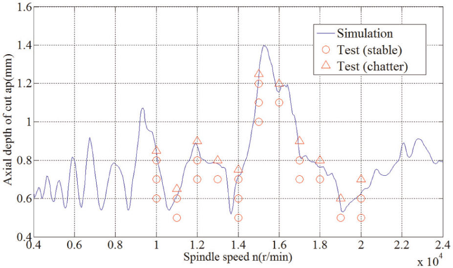
Comparison of predicted and measured chatter stability for inner corner milling.
In order to verify the predicted stability lobes diagram in axial depth of cut, the cutting tests were conducted at the spindle speeds continuously growing from 10,000 to 20,000 r/min with a step size of 1000 r/min. For each of these spindle speeds, the initial axial depth of cut was set according to the simulation results and increased until chatter occurs with a step size of 0.1 or 0.05 mm. Cutting noise that was recorded by a microphone was disposed using a MALDAQ module of CutPro version 9.0 to distinguish whether chatter occurs or not in the cutting process. Besides, the chatter stability was further assured by inspection on the precision and quality of the workpiece surface after milling. Finally, the test results are presented in Figure 6, which shows that the predicted stability lobes diagram is in good agreement with the experimental one.
Conclusion
This article focuses on the time-domain simulation of dynamic cutting forces and chatter stability for circular corner milling during which the radial depth of cut, and the intersection of the tool and the workpiece vary continuously along the tool path. Based on the presented geometrical and dynamic model, the dynamic cutting forces are predicted by a time-domain simulation algorithm. Meanwhile, for the solution of dynamics differential equations, the implicit three-step four-order ADAMS numerical analysis method is proposed. Furthermore, as the two chatter stability criterions which include the PTP method and the dynamic/static forces method are applied, the reliable chatter stability lobes diagram can be obtained. Finally, with the results of the cutting force coefficients of the workpiece material and the modal parameters of the machining system, circular corner milling verification experiments are conducted. The corresponding algorithms of both the proposed cutting forces and the chatter stability predictions are verified in good agreement with the simulation results of cutting tests, which provides an effective way to optimize cutting conditions for circular corner milling in industry applications.
Footnotes
Appendix 1
Declaration of conflicting interests
The authors declare that there is no conflict of interest.
Funding
This article is supported by the National Science and Technology Major Project “High-Grade CNC Machine Tools and Basic Manufacturing Equipments” (grant nos 2011ZX04016-021 and 2010ZX04014-017) and the National Natural Science Foundation of China (grant no. 51375160).