
Abstract
Machining of metal matrix composites has always been challenges for manufacturing engineers due to the presence of hard and brittle reinforced particles. In this article, a new way of alternate application of electrical discharge grinding and abrasive grinding has been applied through the use of slotted grinding wheel. The developed machining process has been named as slotted electrical discharge abrasive grinding. The performances of slotted electrical discharge abrasive grinding process are tested on aluminum–silicon carbide–graphite (Al/SiC/Gr) metal matrix composite workpiece. The experiments were performed using one parameter at a time approach considering the effect of current, pulse on-time, pulse off-time, wheel speed and grit number on material removal rate and average surface roughness. It has been found that current ranges from 3 to 15 A and wheel speed ranges from 700 to 1300 r/min are more appropriate for machining of Al/SiC/Gr composite material within the ranges of selected parameters.
Keywords
Introduction
Aluminum metal matrix materials reinforced by silicon carbide (SiC) are widely used in automobile and aerospace industries due to their superior physical and mechanical properties. These materials are replacing the heavy parts made of cast iron and steel in automobile, aircraft and railway industries due to their lightweight and high strength characteristics. 1 Due to the presence of ceramic particles into matrix, the machining of composites becomes difficult and leads to rapid tool wears, if they are machined with cutting-based machining operations. Generally, diamond grinding (DG) has been used successfully for machining of these materials, but high grinding forces, wheel loading and high cost of diamond particles limit the wide applications of metal matrix composites (MMCs).2,3 Among the various unconventional machining processes, electrical discharge machining (EDM) gives better performances as compared to the other advanced machining processes with low productivity. 4 Therefore, machining of MMCs is still a challenge for manufacturing industries. To overcome these problems, a new way of hybrid machining process (HMP) has been developed, where alternatively electrical discharge grinding (EDG) and abrasive grinding (AG) have been applied for machining. The developed process is named as slotted electrical discharge abrasive grinding (SEDAG).
SEDAG process is an innovative HMP that comprises the EDG and AG in sequential mode due to rotation of wheel. It is more suitable for machining of the electrically conductive hard and brittle materials. In this process, a compound grinding wheel called as slotted grinding wheel has been used for machining. The slotted wheel was made of mild steel disk, whose periphery is cut into slots and teeth. To find a circular wheel with abrasive nature, the vitrified bonded diamond abrasives are placed into the slots made around the periphery of the metallic disk. The diamond particles are used as an abrasive material due to their high hardness, high wear resistance and suitability for machining of the MMCs. 2 However, the vitrified bond has better bonding strength than resin bond at high temperature. 5 Therefore, these two materials are filled into the slots between the metallic teeth to get the circular erosion–abrasion-based compound wheel.
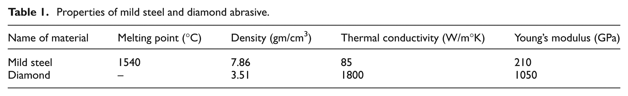
For the development of slotted grinding wheel, a circular disk made of mild steel (diameter = 100 mm, thickness = 5 mm and central hole diameter = 32 mm) was obtained after machining. The slots and teeth are cut at periphery of disk on milling machine in equal number and at equal peripheral length. After this, trapezoidal-shaped vitrified bonded diamond sticks were developed with the help of die and entrapped into the slots. The metallic disk with diamond sticks was kept into a circular die for hot compacting and sintering purposes. After proper compacting and sintering, a circular wheel was obtained. Furthermore, the wheel was machined on a diamond grinder, and finally, a uniform circular slotted grinding wheel was obtained, which is manufactured by Kompex India Ltd, New Delhi. The teeth and diamond sticks of the developed wheel are used for spark erosion and abrasive abrasion purposes, respectively. The mechanical properties of mild steel and diamond abrasive are shown in Table 1.
Properties of mild steel and diamond abrasive.
The machining mechanism with slotted grinding wheel is shown in Figure 1. In this process, the material removal phenomenon is completed in two alternate phases, that is, spark erosion and abrasive abrasion as shown in Figure 2. The spark erosion phenomenon occurs, when direct current (DC) pulse supply of EDM machine is applied between metallic tooth and workpiece while engagement of abrasive particles is responsible for abrasive abrasion phenomenon. First, the spark is generated between metallic tooth of wheel and workpiece due to the movement of high-velocity ions and electrons at the cathode and anode during pulse on-time. Due to this, high heat is generated, resulting in melting and vaporization of workpiece material and softening of workpiece material below melt zone. Suddenly sparks collapsed during pulse off-time and molten material flushed out by dielectric fluid. These phenomena were repeated till the peripheral length of the entire tooth. After this, abrasive particles come in contact with workpiece, and abrasive abrasion is started. Due to the engagement of abrasive particles, grinding mechanism such as shearing, tearing and plowing actions takes place, and the material is removed by abrasion from the workpiece surface. Therefore, sequential applications of these two processes occur during machining, and material removal is equal to the sum of the individual effect of each process.
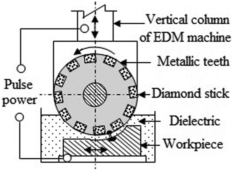
Application of slotted grinding wheel during SEDAG process.
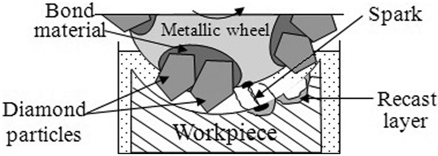
Erosion and abrasion phenomena. 6
In the past, many researchers studied the performance characteristics of DG and EDG in cut-off grinding configuration. They were used in uniform metal-bonded diamond wheel for simultaneous spark erosion and abrasive abrasion purposes and named as electrical discharge diamond grinding (EDDG) process. Koshy et al. 7 focused their studies on material removal mechanism of EDDG process and claimed that electric discharges are used to thermally soften the work material, resulting in the decrease in grinding forces and specific energy. Choudhury et al. 8 studied the effect of current, voltage, pulse on-time and duty factor on material removal rate (MRR) and grinding forces and experimentally proved that lower discharge voltage is more suitable for the EDDG process as compared to the higher discharge voltage. Jain and Mote 9 found that specific energy required in EDDG process is much lower than EDG process. Yadav et al. 10 found that wheel speed was a more significant parameter during EDDG of high speed steel (HSS) workpiece.
Several researchers developed EDDG process in face grinding mode to study the machining behavior of the process. Singh et al.11,12 worked on EDDG process in face grinding mode for machining of the WC-Co composite and HSS workpieces considering the effect of wheel speed, current, pulse on-time and duty factor on MRR, Ra and wheel wear rate (WWR). They found that the material removal capability of diamond wheel declined at low current and high wheel speed due to wheel glazing. 11 Yadav and Yadava13,14 claimed that the SEDAG process gives better performance than EDM and EDG processes. They also optimized the process parameters during SEDAG of Al/SiC/Gr composite. 6 They also suggested that developed SEDAG process effectively removed the drawbacks of existing EDDG process such as high wheel wear, abnormal arcing and frequently short circuiting due to alternate application of spark erosion and abrasion phenomena.
The aim of this article is to study the effect of the use of compound (slotted) wheel rather than a full metal-bonded diamond wheel in cut-off grinding mode. The SEDAG process so developed has been applied for machining of Al/SiC/Gr metal matrix hybrid composite. In this study, the effect of current, pulse on-time, pulse off-time, wheel speed and grit number of abrasives on MRR and Ra has been investigated and presented.
Experimentation
All the experiments were performed on Sparkonix ZNC EDM (model: S 50 ZNC) machine mounted with a separate attachment on its vertical column with a provision for providing rotation to the grinding wheel. The actual photographic view of experimental setup is shown in Figure 3. The slotted grinding wheel is mounted on the horizontal shaft, which is rotated by DC motor with the help of V-pulley and belt. The servo control mechanism of EDM machine is used to maintain the constant gap between workpiece and wheel. The spark is generated between toothed parts of wheel and workpiece, when DC pulse power supply was applied by the machine. The gap between workpiece and wheel is filled with dielectric (EDM oil) fluid.
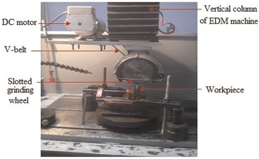
Experimental setup on EDM machine.
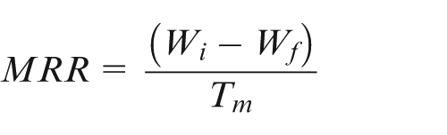
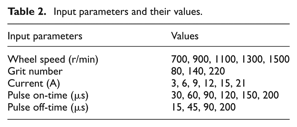
All the experiments were performed using one parameter at a time approach. 15 The values of various input parameters are given in Table 2. Polarity of tool and workpiece has been chosen as positive (+) and negative (−), respectively, because positive tool polarity gives higher MRR than negative polarity. 16 Generally, MRR reflects the productivity, while Ra refers to the quality of the product; thus, these parameters are selected as output responses. The MRR is calculated by dividing the weight loss of workpiece by machining time, which is determined as
Input parameters and their values.
where Wi is the initial weight of workpiece before machining, Wf is the final weight of workpiece after machining and Tm is the machining time.
For measurement of the weight of workpiece before and after machining, a digital micro-weighing balance (model: CAUW-D) was used. The other response parameter Ra was measured at three different points for each machined surface, and the average value was used for the analysis of the experimental data. A digital surface measuring instrument (model: Surtronic-25, cut-off length: 0.08 mm) was used to measure the average surface roughness of the machined surfaces.
The experiments were performed on a hybrid composite comprising aluminum alloy as a matrix material and SiC and Gr particles as reinforcing materials. Generally, Al/SiC composites are widely used in automobile, aerospace and nuclear industries. By adding graphite particles into aluminum matrix with silicon carbide, it becomes hybrid MMCs of Al/SiC/Gr and gains additional properties of self-lubricating. Therefore, it becomes more advantageous and applicable to inaccessible places where proper lubrications are impossible. It is also applicable for valve and valve seat, piston and piston ring, cam follower, metal-bonded abrasive wheel for dry grinding and equipments for nuclear furnace. Thus, with the wide applicability and difficulty in machining, the Al/SiC/Gr composite has been selected as a workpiece material for this study.
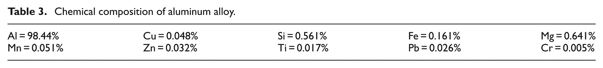
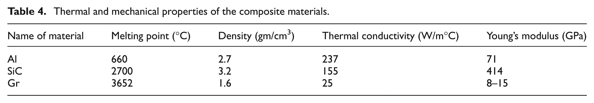
The specimen pieces of Al/SiC/Gr composites are commercially not available; hence, it was made by stir casting method. For the development of specimen pieces, aluminum alloy was reinforced with 10% volume of SiC and 10% volume of Gr with an average particle size of 37 µm of each reinforced materials. The chemical composition of aluminum alloy is given in Table 3, while Table 4 shows the thermal and mechanical properties of the composite materials. First, the aluminum alloy was melted in a graphite crucible up to 850 °C and then it was stirred for 30 min at 300 r/min. Then, the preheated mixture (300 °C) of silicon carbide and graphite particles was slowly introduced into the molten aluminum matrix and again stirred for 30 min. Finally, the molten mixture was poured into a pre-designed mold, and after solidification, the desired size (50 mm × 10 mm × 5 mm) of workpiece specimen was taken out of the mold cavity.
Chemical composition of aluminum alloy.
Thermal and mechanical properties of the composite materials.
Results and discussion
Comparison between EDM and SEDAG
To know the feasibility of developed process, the performances of SEDAG are compared with the well-known EDM process at constant EDM parameters such as current (12 A), pulse on-time (120 µs) and pulse off-time (90 µs) with the developed slotted grinding wheel of grit number-80. First, the slotted wheel was kept stationary, and the metallic tooth was made contact with the workpiece to perform EDM process. In the second case, it rotates with 1300 r/min to perform SEDAG process. The comparative experimentations were performed on Al/SiC/Gr composite workpiece. The actual photograph of the workpiece after machining is shown in Figure 4, while Figure 5(a) and (b) shows the scanning electron microscopic (SEM) image of the workpiece surface after EDM and SEDAG processes, respectively. The analysis of experimentations to evaluate the performances of the machining processes is shown in Figure 6(a) and (b).
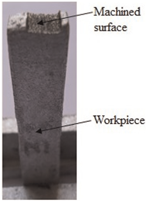
Workpiece after machining.
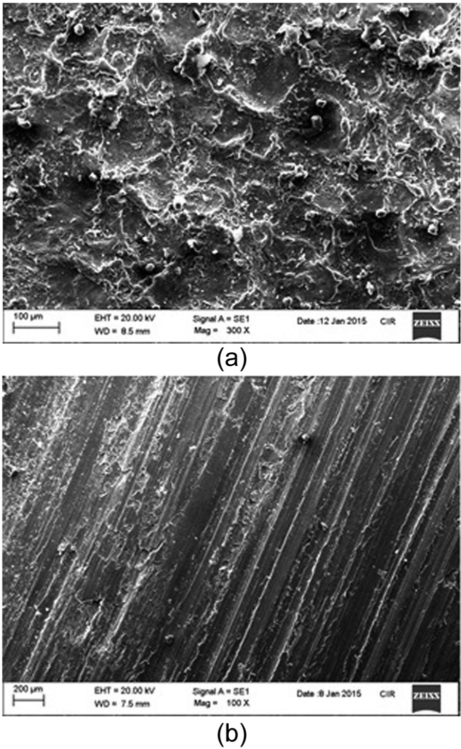
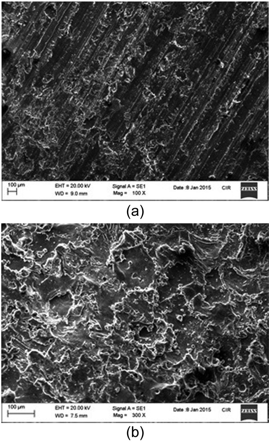
(a) EDM-machined surface and (b) SEDAG-machined surface.
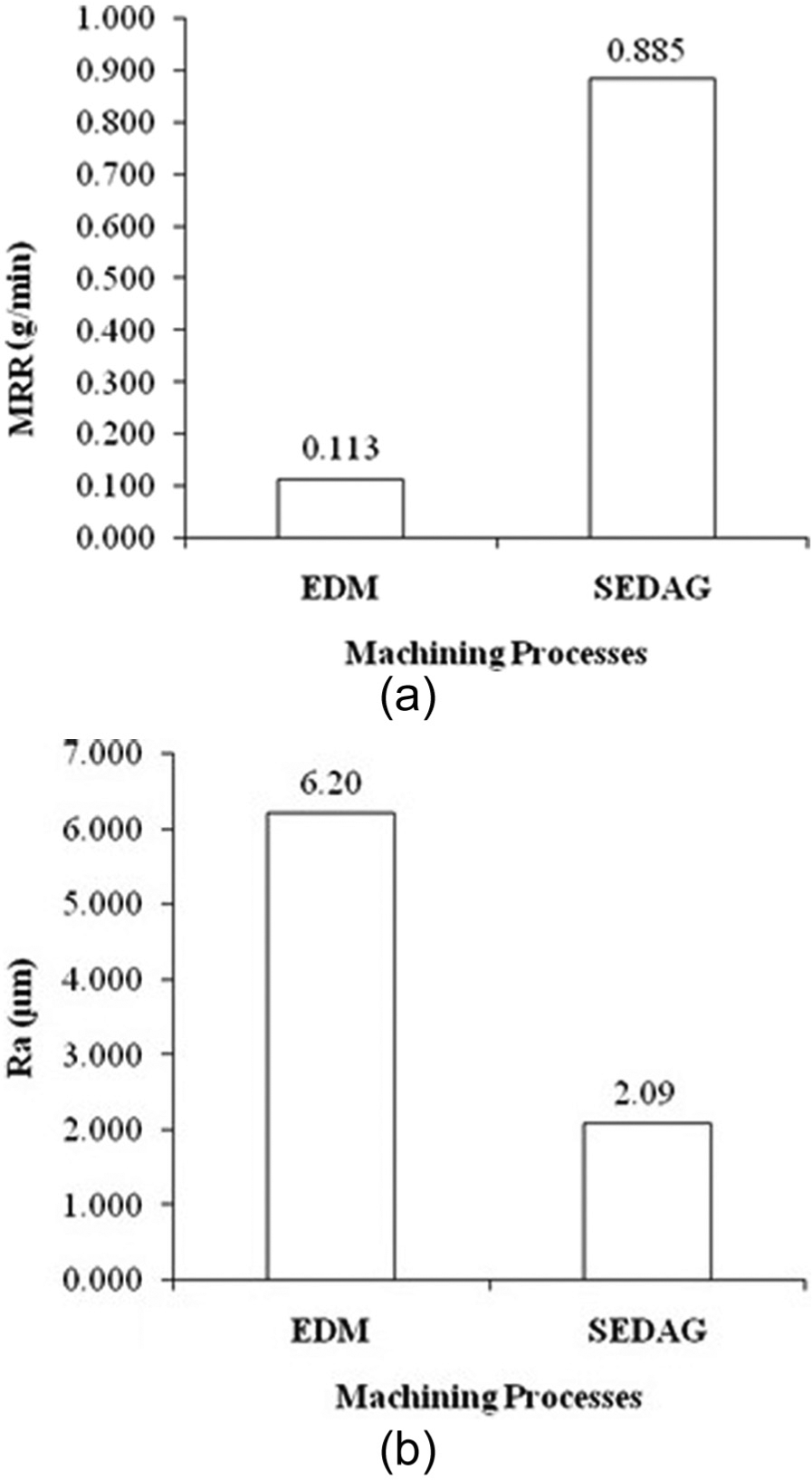
Effect of EDM and SEDAG processes on (a) MRR and (b) Ra.
Figure 6(a) shows that SEDAG process gives higher (about eight times) MRR as compared to the EDM process due to the effective erosion and abrasion actions. In EDM process, molten material is partially removed from the workpiece surface and partially resolidified, resulting in the formation of a recast layer as shown in Figure 5(a). It has been observed that the loose reinforcement particles lying on the workpiece surface due to the ineffective flushing, resulting in the decline of MRR and surface finish. Figure 6(b) shows that the SEDAG process gives a better surface finish as compared to the EDM. This is because a lot of abrasives make contact during the abrasion process and remove the recast layer with loose particles from the workpiece surface; as a result, a better surface finish is obtained, as shown in Figure 5(b).
Effect of current
Figure 7 shows the variation of MRR with respect to current for different grit numbers (80, 140 and 220) of abrasive particles, while other parameters are kept constant, such as pulse on-time (90 µs), pulse off-time (45 µs) and wheel speed (900 r/min). It has been observed that MRR increases with the increase in current up to 15 A and then decreases for all grit numbers of abrasives. This is because the spark energy increases with the increase in the current; thus, more heat energy is transmitted into the workpiece. Due to this, a large amount of material is melted and softened below melt zone. The melted material is removed during pulse off-time of EDG process, while softened material is removed during grinding process, resulting in the increase in MRR. With the increase in current beyond 15 A, relatively large amount of spark energy is generated, which results in the melting of material in large volume. Due to this, the pulse off-time becomes insufficient to remove the molten material completely from the workpiece surface, which results in the formation of a recast layer on the workpiece surface. Therefore, the total width of the recast layer with softened layer becomes so high, making the protrusion heights of abrasive particles inefficient to remove the total width during abrasion, which results in the decrease in MRR.
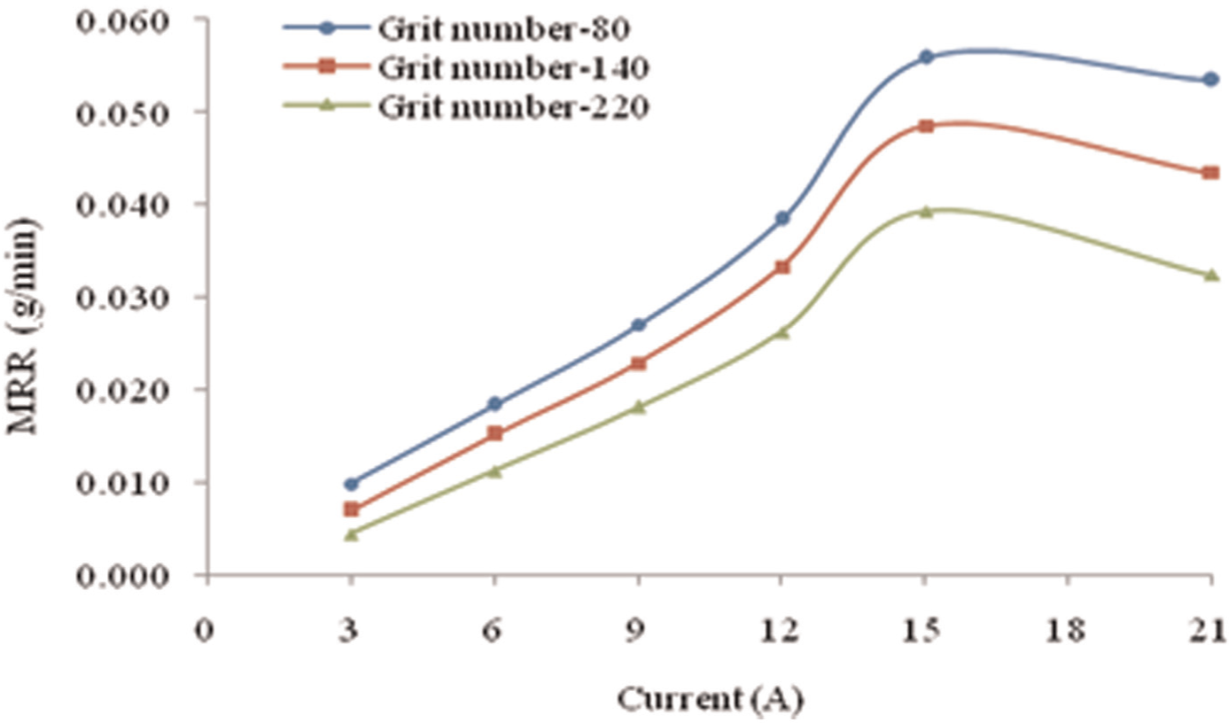
Effect of current on MRR with different grit numbers.
For a particular current, it is also observed (Figure 7) that lower grit number of abrasives gives higher MRR as compared to the higher grit number of abrasive particles. The lower grit number of abrasives are larger in size as compared to higher grit number of abrasives; thus, the protrusion heights of lower grit number of abrasives are higher. Due to this, lower grit number of abrasives effectively removed the softer material from the workpiece surface, resulting in the increase in MRR.
Figure 8 shows the variation of Ra with respect to current for different grit numbers of abrasives, while other parameters are kept constant, such as pulse on-time (90 µs), pulse off-time (45 µs) and wheel speed (900 r/min). It is observed that Ra value increases with the increase in current for all the grit numbers of abrasives. An increase in current means more heat energy transferred to the workpiece, resulting in the formation of deeper and wider craters which increase in Ra value. For a particular current, it has been also observed that higher grit number of abrasives gives better finish than lower grit number of abrasives. The higher grit number of abrasives means smaller particle size; thus, a large number of abrasive particles make contact on the workpiece surface in a small area during grinding. Therefore, the amount of material removed by each particle is very small, and as a result, a better surface finish has been obtained.
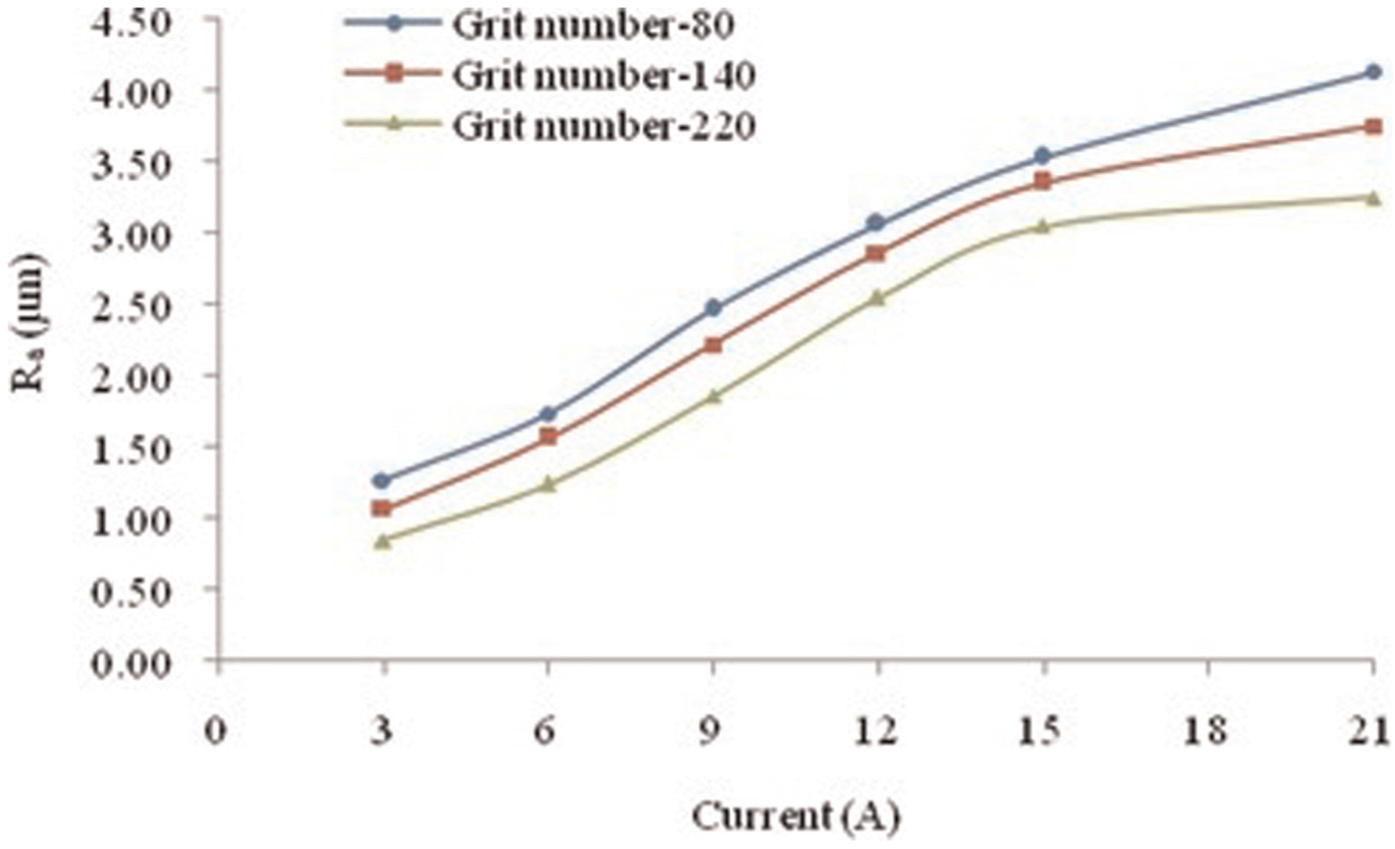
Effect of current on Ra with different grit numbers.
Effect of pulse on-time
Figure 9 shows the variation of MRR with respect to pulse on-time for different grit numbers of abrasives while other parameters are kept constant, such as current (9 A), pulse off-time (45 µs) and wheel speed (900 r/min). It is observed that MRR increases with the increase in pulse on-time for all grit numbers of abrasives. An increase in pulse on-time means relatively longer time available for each electrical discharge. Thus, heat energy is transmitted into the workpiece per spark relatively for a longer time. Due to this, a higher volume of workpiece materials are melted and softened below the molten material, which is removed by EDG and the grinding process separately, resulting in MRR increases. For a particular pulse on-time, it is also observed that lower grit number of abrasive gives high MRR as compared to higher grit number of abrasive due to effective protrusion heights.
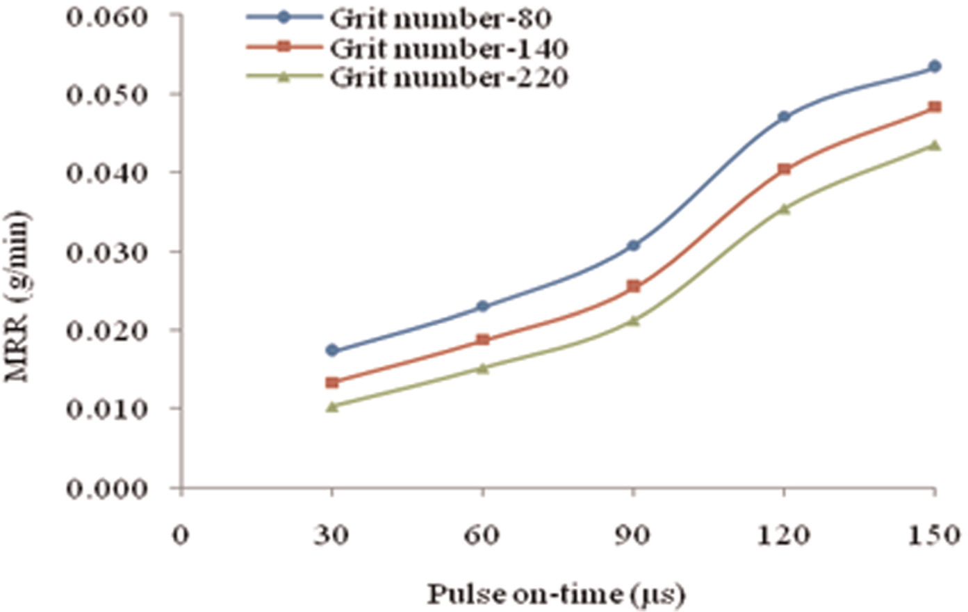
Effect of pulse on-time on MRR with different grit numbers.
It is also observed (Figure 9) that MRR increases with steady rate with the increase in pulse on-time from 30 to 90 µs, but in between pulse on-time of 90 and 120 µs, it increases suddenly and after that it decreases slightly. This is because the range of pulse on-time from 90 to 120 µs is more appropriate; hence, molten materials with softened layer are completely removed during machining which results in the sudden increase in MRR. Pulse on-time beyond 120 µs responsible for the melting of a huge volume of material, but some of the discharge energy consumed to maintain the constant temperature of the molten material results in a slight decline in MRR.
Figure 10 shows the effect of pulse on-time on Ra with different grit numbers of abrasives, while other parameters are kept constant, such as current (9 A), pulse off-time (45 µs) and wheel speed (900 r/min). It is observed that Ra value increases with the increase in pulse on-time for all abrasives. This is due to the fact that increase in pulse on-time means longer duration for each discharge; as a result, a large volume of material is melted. Due to this, large craters are formed after ejection of molten material metal from the workpiece surface, resulting in the increase in roughness value. For a particular pulse on-time, it is also observed that higher grit number of abrasive gives better surface finish, as compared to lower grit number of abrasives, due to the removal of material in small amount by each abrasive particle.
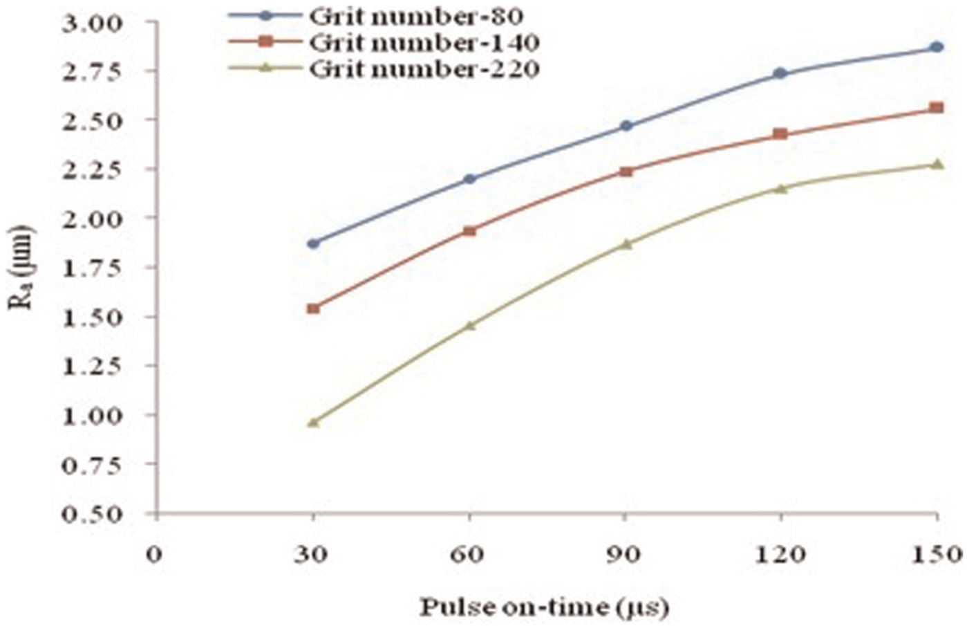
Effect of pulse on-time on Ra with different grit numbers.
Effect of pulse off-time
Figure 11 shows the variation of MRR with respect to pulse off-time with different grit numbers of abrasives, while other parameters are kept constant, such as current (9 A), pulse on-time (90 µs) and wheel speed (900 r/min). It has been observed that MRR increases with the increase in pulse off-time for all the abrasives. This is because an increase in pulse off-time means longer time available for ejection of molten material; hence, molten material is completely removed, which results in the increase in MRR. It is also observed (Figure 11) that higher MRR is achieved with lower grit number of abrasives due to effective removal of material by lower grit number of abrasives.
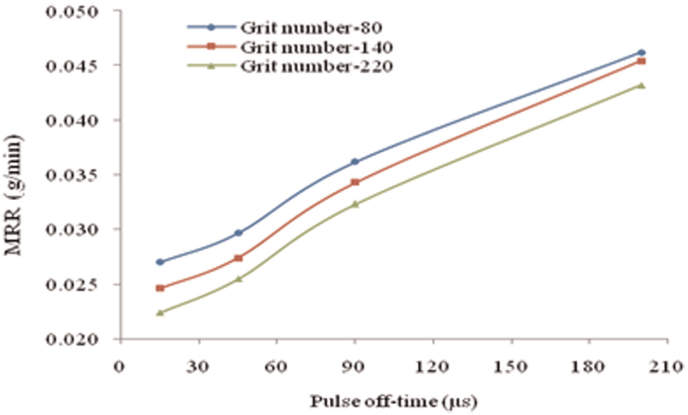
Effect of pulse off-time on MRR with different grit numbers.
Figure 12 shows the variation of Ra with respect to pulse off-time with different grit numbers of abrasives, while other parameters are kept constant, such as current (9 A), pulse on-time (90 µs) and wheel speed (900 r/min). It is observed that Ra value increases with the increase in the pulse off-time for all the abrasives. An increase in the pulse off-time means large amount of fresh dielectric enters into the gap for a longer time. Thus, the softer workpiece material becomes harder due to quenching effect. Due to the hard surface, abrasive particles are blunted rapidly during grinding, and as a result, Ra value increases. It is also observed (for a particular pulse off-time) that roughness value decreases with higher grit number of abrasives which is followed by lower grit number of abrasives. This is because a small amount of material is removed by each particle of higher grit number of abrasives.
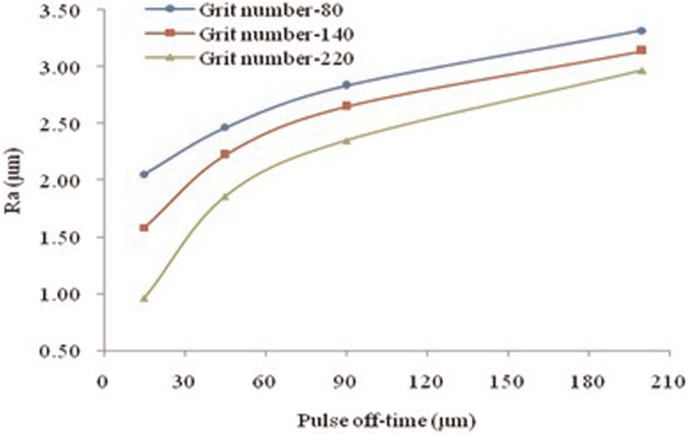
Effect of pulse off-time on Ra with different grit numbers.
Effect of wheel speed
Figure 13 shows the effect of wheel speed on MRR with various grit numbers of abrasives, while other input parameters are kept constant, such as current (9 A), pulse on-time (90 µs) and pulse off-time (45 µs). It is observed that MRR increases with the increase in wheel speed for all the grit numbers of abrasives up to 1300 r/min and then decreases. An increase in wheel speed means increases in the flushing efficiency. Thus, molten material is effectively removed during off-time, resulting in the increase in MRR. It may be also possible that the gap is properly cleaned, and thus, debris accumulation could not take place in the gap due to high flushing efficiency, and as a result, more stable sparks are generated and MRR increases. It is also observed (for a particular wheel speed) that lower grit number of abrasive gives higher MRR due to the effective protrusion height of abrasive particles.
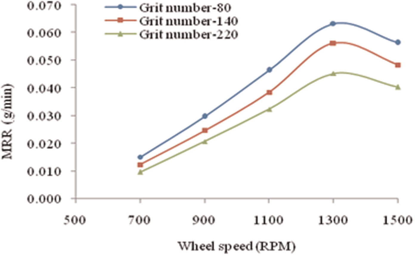
Effect of wheel speed on MRR with different grit numbers.
It is also observed (Figure 13) that MRR decreases with the increase in the wheel speed beyond 1300 r/min with all the abrasives. At higher wheel speed, the metallic teeth make contact with the workpiece for a shorter time, and thus, there is insufficient time for spark generation. As a result, instable sparks are generated which have an adverse effect on the MRR. It may be also possible that peripheral speed of wheel protects the dielectric which is entering into the gap at higher wheel speed. Thus, the process behaves similarly to dry grinding, resulting in abrasive particles being blunted rapidly and a decrease in MRR.
Figure 14 shows the variation of Ra with respect to wheel speed with different grit numbers of abrasives, while other parameters are kept constant, such as current (9 A), pulse on-time (90 µs) and pulse off-time (45 µs). It has been observed that Ra value decreases with the increase in wheel speed up to 1300 r/min for all the abrasives and then increases. An increase in the wheel speed means increases in the peripheral speed of wheel; hence, more kinetic energy is transmitted to dielectric, which enhanced the flushing efficiency. Thus, the molten material is completely ejected from the workpiece surface, and no recast layer is formed and as a result Ra value decreases. It may be also possible that large numbers of abrasive particles make contact with the workpiece surface at higher wheel speed and as a result Ra value decreases.
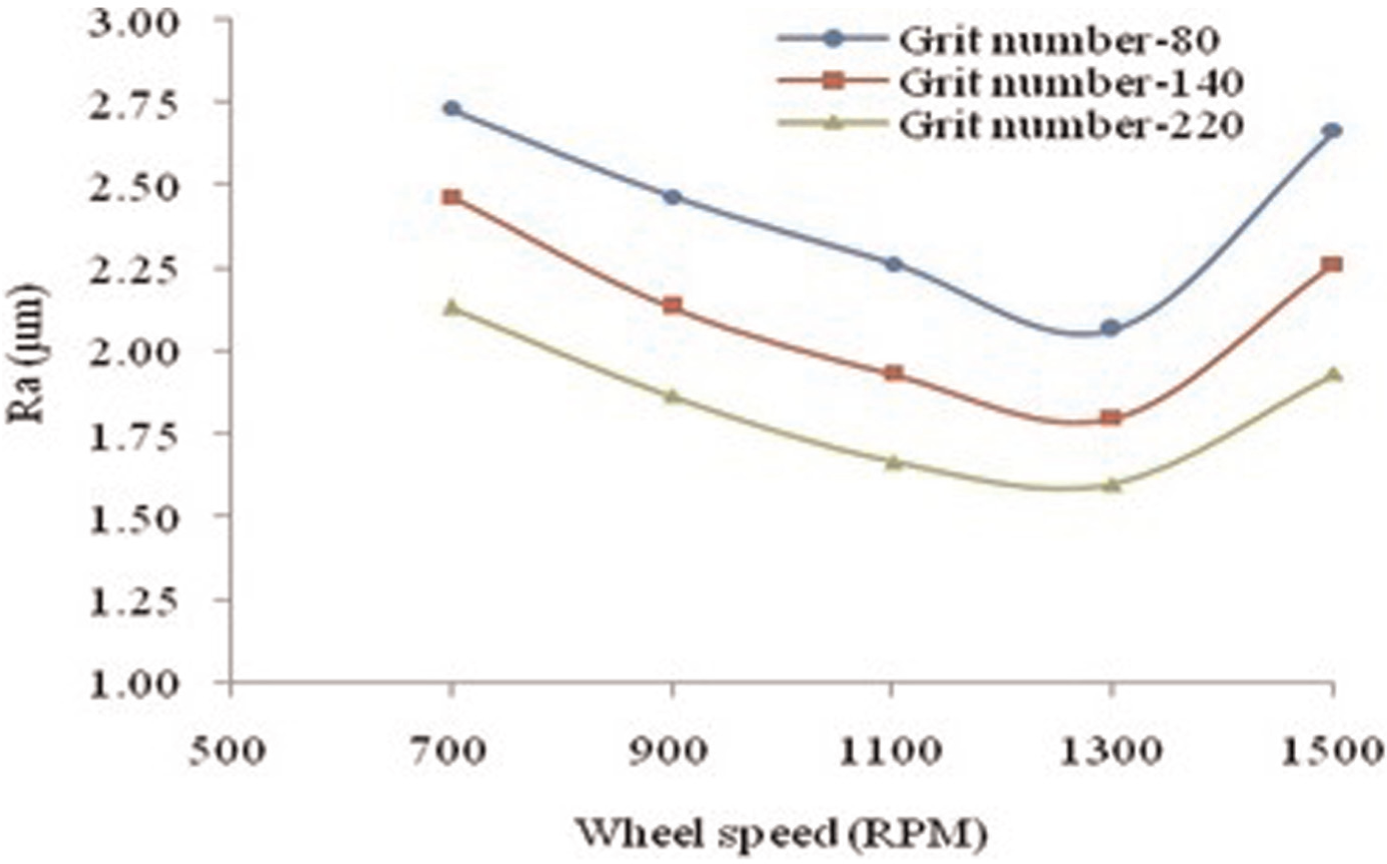
Effect of wheel speed on Ra with different grit numbers.
It is also observed (Figure 14) that Ra value increases with the increase in the wheel speed beyond 1300 r/min for all the grit numbers of abrasives. There are many reasons for the increase in the Ra value at high wheel speed. At higher wheel speed, weak and unstable sparks are generated as Ra value increases. It may be also possible that at high wheel speed, insufficient amount of dielectric entered into the inter electrode gap due to high peripheral speed. Hence, debris particles accumulate in the gap, and as a result, abnormal arcing or spark takes place, resulting in the increase in the Ra value. It may be also possible that the process behaves similar to dry grinding, resulting in rapid loss in cutting ability of abrasives and increase in the Ra value.
SEM analysis
SEM micrographs of machined surface are shown in Figure 15(a) and (b). The recast layers and abrasion marks are shown in Figure 15(a) as a result of decline in MRR and surface finish. There are many causes such as higher pulse current, longer pulse on-time, insufficient pulse off-time and ineffective protrusion heights of abrasive particles. Figure 15(b) shows the recast layers with craters on the machined surface. This is possible at longer pulse on-time because there is sufficient time for melting of the matrix material surrounding the reinforcements. Due to this, matrix materials surrounding the reinforcements are melted, and the reinforcements are easily pulled out from the matrix and formed pits. These phenomena lead to decreases in MRR and increases in the Ra value of the machined surfaces. The insufficient pulse off-time at longer pulse on-time is responsible for the formation of the recast layers.
(a and b) SEM images of machined surface.
In EDM process, the reinforcement particles are not melted during sparking and are only removed or made free after melting of the bonded metal surrounding them as shown in Figure 5(a). These phenomena are also responsible for abnormal arcing, resulting in the decline in the MRR and Ra values. The free or loose abrasive particles are easily pulled out during SEDAG process as shown in Figure 5(b), resulting in better machining performances in terms of higher MRR with better surface finish.
Conclusions
In this study, the performances of SEDAG process are tested on Al/SiC/Gr composite considering the effect of current, pulse on-time, pulse off-time, wheel speed and grit number on MRR and Ra. Following conclusions are drawn from the experimental studies:
SEDAG process gives better performances in terms of higher MRR and better surface finish as compared to EDM process due to effective application of the erosion–abrasion phenomena.
The lower grit number of abrasive gives higher MRR but simultaneously surface finish deteriorates. Thus, lower grit number of abrasives is suggested for rough machining, while finish operation is done with higher grit number of abrasives.
MRR increases with the increase in current and pulse off-time with simultaneous improvement in the surface roughness due to the ineffectiveness of the protrusion heights at the higher current and longer pulse on-time.
MRR and Ra values increase with the increase in the pulse off-time within the range of selected input parameters.
MRR increases with the increase in the wheel speed with simultaneous improvement in the surface finish due to the enhancement in the flushing efficiency of dielectric fluid. After appropriate value of the wheel speed, the process behaves similar to dry grinding, and MRR and Ra values are declined.
Footnotes
Acknowledgements
The authors are extremely thankful to Dr S.K.S. Yadav, Mechanical Engineering Department, HBTI, Kanpur, India, for his support and providing the EDM machine to conduct the actual experimental works.
Declaration of conflicting interests
The author(s) declared no potential conflicts of interest with respect to the research, authorship, and/or publication of this article.
Funding
The author(s) received no financial support for the research, authorship, and/or publication of this article.