
Abstract
This work investigates the effects of cutting parameters on surface roughness (Ra, µm), cutting temperature (T, °C) at the chip–tool interface and the material removal rate during hard machining of AISI 1015 (43 ± 1 HRC) steel using carbide insert under dry and spray impingement cooling environment. A combined technique using orthogonal array and analysis of variance was employed to investigate the contribution of spindle speed, feed rate, depth of cut and air pressure on responses. It is observed that with spray impingement cooling, cutting performance improves compared to dry cutting. The predicted multi-response optimization setting (N3-f1-d1-P2) ensures minimization of surface roughness, cutting temperature and maximization of material removal rate.
Keywords
Introduction
Machining operation such as hard turning is the most suitable finishing process because some processes such as rough machining and fine grinding are eliminated. Hard turning generally involves three sequential steps of manufacturing hardened components, that is, rough machining of unhardened steel, heat treated to the required hardness and finish machining to the required dimensional accuracy as reported by Konig et al. 1 During the process of hard turning, large amount of heat is generated at the chip–tool interface. This heat generation has large effect on life of the cutting tools as well as surface quality of the workpiece. Therefore, in hard turning, selection of suitable cutting parameters, superior cutting tool such as coated carbide or ceramic insert and workpiece material are important to improve quality response and high material removed.
Although by introduction of cutting fluid at the cutting zone, better cutting performance can be achieved, which will result in better surface finish, low cutting force and reduction of tool wear as reported by Dhar et al. 2 But, in recent years, according to the regulations of Occupational Safety and Health Administration (OSHA), using coolant liquid possesses threat to the environment. Under dry environment, metal cutting is considered as safety to the environment by Sreejith and Ngoi. 3 Therefore, materials with hardness within the range of 40–45 HRC are to be studied under the proper selection of cutting parameters such as cutting speed, feed rate and depth of cut (DoC) and even other factors such as air pressure or water pressure.
De Lima et al. 4 studied the turning of AISI 4340 steel hardened from 250 to 525 HV using coated carbide tools in order to investigate whether this cutting tool grade is capable of providing a satisfactory performance when machining steel with increasing levels of hardness. Abrasion was the principal wear mechanism observed and catastrophic failure took place when attempting to machine the 525 HV steel. Dinc et al. 5 presented in their work on heat transfer analysis of metal cutting that the temperature at the tool–work interface increases quickly due to the speed of the cut. Increased speed is good for tool life because it converts more heat into energy that is carried away by the chip. Increased cutting speeds resulted in decreased machine surface temperatures due to the higher metal removal rate, which results in more heat being carried away by the chip and thus less heat being conducted into the workpiece. Similar results were also reported by O’Sullivan and Cotterell 6 when machining Al 6082-T6. Feed causes the frictional force created by the tool motion against the workpiece. Tool geometry also attributes to heat generation. The shape of a tool when it contacts the surface of the workpiece, while it is in rotation, could decrease or increase the amount of heat generated by the cutting process is explained by Boothroyd and Knight. 7 Byrne et al. 8 have indicated that the turning of various types of steel can be performed under dry cutting conditions in concerns related to the environmental problems associated with cutting fluids, and this dry machining cutting condition is set to continue. Trent 9 found that when cutting speed increases, both radial and feed forces tend to decrease due to temperature increase, and partly to the decreasing of the chip–tool contact length. Additionally, the DoC apparently has an influence larger than the cutting speed and feed rate has a moderate effect on forces. In general, when machining steel with coated carbide tools, different tool wear mechanisms occur, such as abrasion, adhesion, oxidation and even some diffusion, which act simultaneously and in proportions depending mainly on the temperature as suggested by Usui. 10 Ezugwu et al. 11 have found that temperature can reach up to 1500 °C during machining of stainless steel with carbide tool in conventional lathe. Therefore, water-based fluid is widely used to dissipate the heat in order to reduce the strength of the cutting tool, leading to tool failure by diffusion wear. CheHaron et al. 12 reported that wet cutting was better than dry cutting for coated carbide tools when machining tool steels (23 HRC). However, Khrais and Lin 13 studied wear mechanisms and tool performances of TiAlN physical vapour deposition (PVD)–coated inserts during machining of AISI 4140 steels at high speeds for both dry and wet machining. Dry cutting was better than wet cutting at around 200–400 m/min speed. Dhar et al. 2 employed minimum quantity lubrication (MQL) machining technique in turning AISI 4340 steel with uncoated carbide tool (SNMM120408). During experimentation, process parameters such as cutting velocity, feed rate and DoC were kept constant at 110 m/min, 0.16 mm/rev and 1.5 mm, respectively. Water-soluble cutting fluid was supplied at flow rate of 60mL/h and mixed with compressed air prior to being impinged on the cutting zone at a high speed. Under same cutting conditions, MQL caused a significant reduction in tool wear and surface roughness as compared to dry and wet turning. Kumar Vikram and Ramamoorthy 14 compared the performance of different coated carbide tools in conventional dry turning and wet turning processes with minimal fluid application method by varying speed and feed keeping the DoC constant. Kumar Vikram et al. 15 compared the performance of TiCN- and TiAlN-coated tools in machining AISI 4340 hardened steel under dry, wet and minimum fluid application conditions. Minimum fluid application yields better result compared to wet and dry machining. However, the performance of the TiAlN-coated tool performed better with reference to wear resistance and surface finish on the components. Benga and Abrao 16 investigated the effect of speed and feed rate on surface roughness and tool life using three-level factorial design (32) on machining of hardened 100Cr6 bearing steel (62–64 HRC) using ceramic and cubic boron nitride (CBN) tools. They found that feed rate is the most significant factor affecting surface finish and cutting speed has very little influence on surface finish for both ceramic and CBN cutting tool. More et al. 17 compared the performance between CBN-TiN-coated inserts and polycrystalline cubic boron nitride (PCBN) tipped inserts in terms of tool wear, surface roughness and cutting forces for the same machining conditions and machining cost on AISI 4340 steel. They found that CBN-TiN-coated carbide inserts demonstrated a tool life of approximately 18–20 min per cutting edge and the surface roughness was below 1.3 µm. For PCBN tools, it produced a tool life of 32 min and constant surface roughness value at cutting conditions of V = 125 m/min, F = 0.15 mm/rev and DoC = 0.25 mm. Also, machining cost using CBN-TiN-coated inserts is between 12% and 30%. El-Wardany et al. 18 investigated experimentally the effect of cutting parameters and tool wear on chip morphology and surface integrity during high-speed machining of D2 tool steel (60–62 HRC) using CBN tool. Lalwani et al. 19 have made an experimental investigation on the effect of cutting parameters such as cutting speed, feed rate and DoC on the feed force, thrust force, cutting force and surface roughness in finish hard turning of MDN250 (50 HRC) steel using coated ceramic tool. They found that the cutting speed has no significant effect on cutting forces and surface roughness. Sahoo and Sahoo 20 studied some machinability studies on flank wear, surface roughness, chip morphology and cutting forces in finish hard turning of AISI 4340 steel using uncoated and multilayer TiN- and ZrCN-coated carbide inserts at higher cutting speed range. The process has also been justified economically for its effective application in hard turning.
The Taguchi method is a systematic application of design and analysis of experiments for the purpose of designing and improving product quality. A high-quality product can be produced quickly and at low cost. It is a relatively simple method that can be used for optimizing different production stages with few experimental runs with several different factors varied together. Davim 21 studied the influence of cutting conditions on the surface finish based on the Taguchi method. The results indicated that the cutting velocity had a greater effect on the roughness, followed by the feed rate. Kopac et al. 22 used the Taguchi design to determine the optimal machining parameters for a desired surface roughness in fine turning of cold preformed steels. They analysed the influence of workpiece material properties, cutting parameters and TiN (PVD) hard coating on the surface roughness. According to their analysis, cutting speed was the most significant influence on the surface quality, and a higher cutting speed resulted in a smoother surface. Asiltürk and Akkus 23 carried out hard turning experiment on hardened AISI 4140 steel (51 HRC) with coated carbide insert using Taguchi orthogonal array for surface roughness. The results of this study indicate that the feed rate has the most significant effect on Ra and Rz. In addition, the effects of two-factor interactions of the feed rate–cutting speed and DoC–cutting speed appear to be important. However, other machinability characteristics such as tool wear, tool life, cutting force, chip morphology and cutting temperature have not been considered for study, which is essential for hard turning. Sahin 24 develops the tool life model using main cutting parameters such as cutting speed, feed rate and cutting tool’s hardness based on the Taguchi method when machining hardened AISI 52100 bearing steels. First-order linear and exponential and second-order predicting equations for tool lives were developed within reasonable error. Furthermore, analysis of variance (ANOVA) was employed to investigate the cutting characteristics of steel bars. Davim and Figueira 25 investigated the machinability evaluation in hard turning of cold work steel (D2) with ceramic tools using statistical techniques. It was concluded that the tool wear was highly influenced by the cutting velocity (57.4%) and, in a smaller degree, by cutting time (13.4%). The specific cutting pressure was also strongly influenced by the feed rate (64.1%) and also the surface roughness is influenced by feed rate (29.6%) and cutting time (32%). Aslan et al. 26 attempted to achieve optimal parameter when turning hardened AISI 4140 steel (63 HRC) with Al2O3+ TiCN mixed ceramic tools using Taguchi techniques. In order to minimize the tool wear, the highest level of the cutting speed, 250 m/min, and the low levels of axial DoC, 0.25 or 0.50 mm, should be preferred. They also developed mathematical model by multiple linear regression. Cutting speed–feed rate and feed rate–axial DoC have been found to be statistically significant on the surface roughness. Sahin and Motorcu 27 developed the surface roughness model using response surface methodology in turning AISI 1050 hardened steels by CBN cutting tools under different conditions. Feed rate was found out to be the most significant factor on the surface roughness. Sahoo and Sahoo 28 presented the mathematical modelling and parametric optimization on flank wear and surfaceroughness based on response surface methodology and grey-based Taguchi method in finish hard turning of AISI 4340 steel (47 ± 1 HRC) using multilayer-coated carbide (TiN/TiCN/Al2O3/TiN) insert under dry environment. The economical feasibility of utilizing multilayer TiN-coated carbide insert has been described. Model adequacy has been checked using correlation coefficients. From main effect, it is evident that cutting speed is the most significant factor for flank wear followed by DoC and feed. Again, feed is the most significant factor for surface roughness followed by cutting speed and DoC.
From the literature review, it is evident that the application of spray impingement cooling in machining of hardened steel component is lacking. This may help to improve the machinability aspects such as reduction of cutting temperature and surface roughness compared to dry machining.
Therefore, an attempt has been made to study the performance of cutting parameters on cutting temperature, surface roughness and material removal rate (MRR) during machining of hardened AISI 1015 (43 ± 1 HRC) steel with carbide inserts under dry and spray impingement cooling environment. The purpose is to compare the machining performances under both environments. The experiment has been planned as per Taguchi L27 orthogonal array. Grey relational approach has been adopted for parametric optimization for spray impingement cooling.
Experimental details
Workpiece material
In this experimental work, AISI 1015 steel is chosen where machining length and its diameter are taken as 150 and 50 mm, respectively. The chemical composition of workpiece by weight percentage analysed by energy-dispersive X-ray spectroscopy (EDX) is as follows: carbon 0.14%, silicon 0.29%, manganese 0.40%, phosphorous 0.021%, sulphur 0.035%, chromium 0.30%, nickel 0.28%, copper 0.30% and molybdenum 0.06%. Hardness of workpiece material after heat treatment was found to be 43 ± 1 HRC (hot rolled).
Cutting insert
In tests, commercially available cemented tungsten carbide inserts (manufactured by WIDIA-Kennametal) of ISO designation SNMG 120408 THM of square type have been used in the experiment. Cutting inserts were mounted on a tool holder of ISO designation PSBNR2525 M12, which gives a maximum approach angle of 75°.
Cutting fluid delivery system
In spray impingement, cutting fluid delivery through spray system was supplied by Spraying Systems India Pvt. Ltd (Bangalore, India). The spray wet machining was done by the air/water spray through one internal mixing air blast nozzle. Spray nozzles used in this study were the air atomizing nozzles (1/8 J and 1/4 J Pressure Spray Set-ups Internal Mix). The spray cooling test set-up was specially designed for the purpose to spray impingement cooling.
Temperature measurement set-up
Fluke Ti32 IR Camera infrared high-performance camera manufactured by Fluke (Everett, WA, USA) was used in this study. This IR Camera can detect minute temperature changes within a scene. Temperature differences as small as 0.018 °C are easily distinguished by the indium antimonide sensor. Higher signal-to-noise (S/N) ratio in reduced frame rate modes of 30 or 15 Hz and integration times as long as 33 and 66 ms, respectively, can be achieved. The details of IR camera specifications for temperature measurements are as follows: range of 20 °C–600 °C and accuracy of ±2 °C or 2%; imaging performances are as follows: frequency of 9 or 60 Hz and minimum focus distance of 46 cm. Finally, smart view full analysis and reporting software were used.
Machine tool
Machining experiments for hard turning tests were performed in a self-centring HMT heavy-duty conventional lathe (NH 22), maximum power of 11 kW and maximum spindle speed of 2040 r/min. The performances are measured during machining, that is, cutting temperature, arithmetic surface roughness average, MRR and finally machining time were calculated.
Surface roughness measurement
The arithmetic surface roughness average (Ra) of the workpiece is measured by Surtronic 25 (Taylor Hobson, Leicester, UK) surface roughness tester, where the cut-off length and assessment length were fixed as 0.8 and 4 mm, respectively. The instrument was calibrated using a standard calibration block prior to the measurements. The measurement was taken around the circumference of the workpieces and repeated four times on the face at different locations of the machined surface, and the average values are reported for the response. The schematic diagram of experimental set-up is shown in Figure 1.
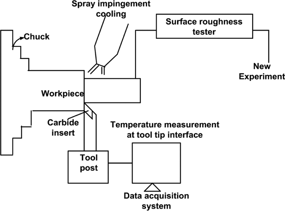
Schematic layout of experiment set-up.
Taguchi design of orthogonal array
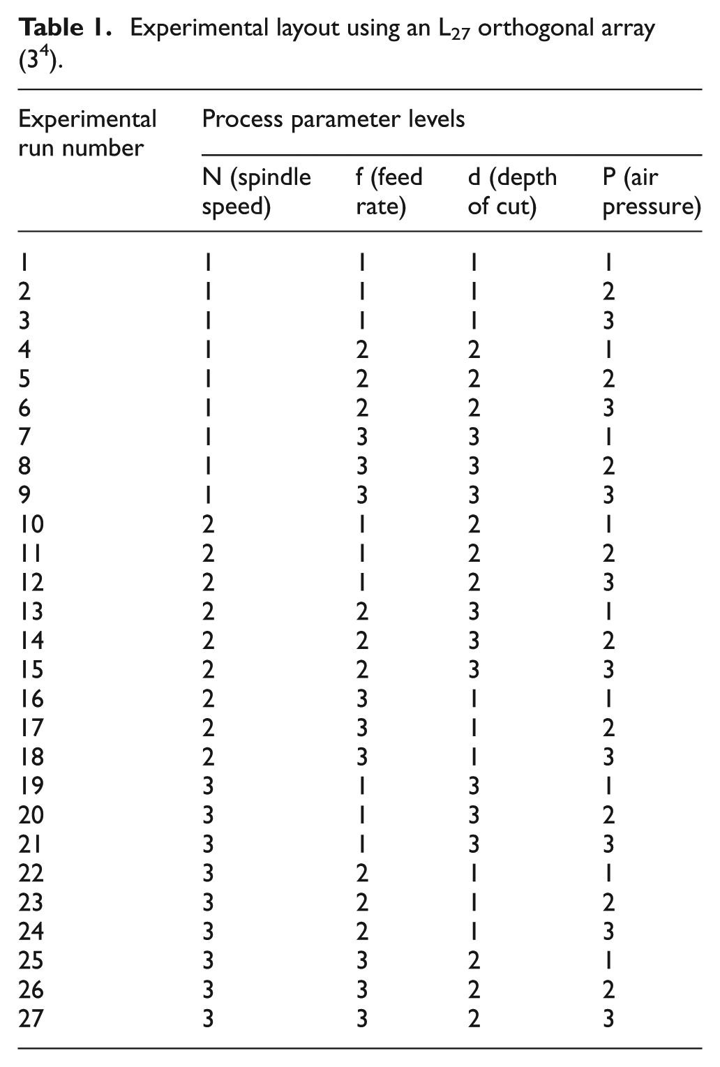
The Taguchi method is a systematic application of design and analysis for experiments. The advantage of Taguchi design of experiment (DOE) is to reduce cost and time in machining by selecting suitable orthogonal array. The data collected from all the experiments in the set are analysed to determine the effect of various design parameters. In this article, L27 orthogonal array (34), which has 27 rows corresponding to the number of tests (26 degrees of freedom) with four columns at three levels, is taken, as shown in Table 1. The first column of the table was assigned to the spindle speed (N, r/min), the second to the feed rate (f, mm/rev), the third to the DoC (d, mm) and fourth to the air pressure (P, bar). The machining experiment was performed at three different levels of cutting parameter, namely, spindle speed (N = 325, 550 and 930 r/min), feed rate (f = 0.04, 0.08 and 0.12 mm/rev), DoC (d = 0.4, 0.8 and 1 mm) and air pressure (P = 1, 1.5 and 2 bar) keeping water pressure (p) constant as 1.0 bar. All the parameters have been selected as per tool manufacturer’s recommendation as well as industrial practices for machining steel with carbide insert SNMG 120408 THM and performance of cutting insert was studied by Taguchi L27 orthogonal array.29,30
Experimental layout using an L27 orthogonal array (34).
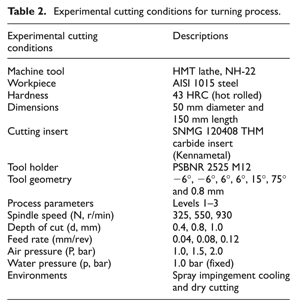
Responses measured are the cutting temperature (T, °C), arithmetic surface roughness average (Ra, µm) and MRR (mm3/min). The results of ANOVA can determine the significance of each process parameters on the outputs. The experimental cutting conditions for hard turning process and experimental layout based on Taguchi L27 orthogonal array for spindle speed, feed rate, DoC and air pressure are shown in Tables 1 and 2.
Experimental cutting conditions for turning process.
Results and discussions
Experimental results by Taguchi L27 orthogonal array under spray impingement cooling are presented in Table 3 and Figures 2–4. Main effect plots for all responses – temperature (T, °C), surface roughness average (Ra, µm) and MRR (mm3/min) with respect to all cutting parameters: spindle speed (N, r/min), feed rate (f, mm/rev), DoC (d, mm) and air pressure (P, bar) at constant water pressure p = 1.0 bar – are shown in the Figures 2–4, respectively. Table 7 indicates the comparisons of experimental responses in spray impingement cooling and dry cutting, respectively. In this case, machining with spray impingement cooling shows better result. In spray impingement, cutting fluid is supplied at high pressure and high velocity, which penetrates (capillary action) into the chip–tool interface that causes the reduction of friction. This cutting fluid chemically reacts to produce a thin solid film of low shear strength, which separates chips and the tool apart. 14 The experimental findings (graphical and statistical analysis) in detail are presented as follows:
Experimental results.
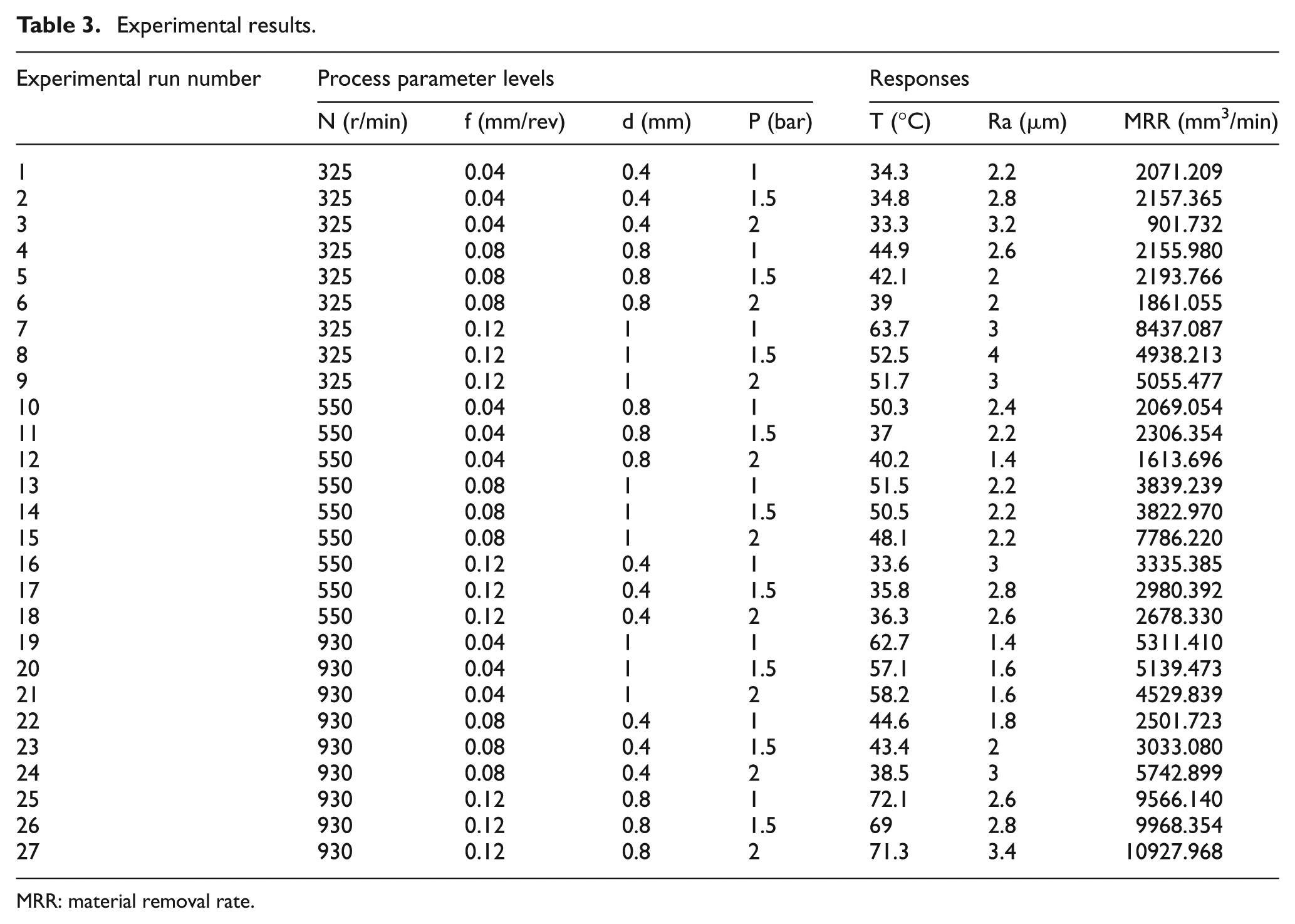
MRR: material removal rate.
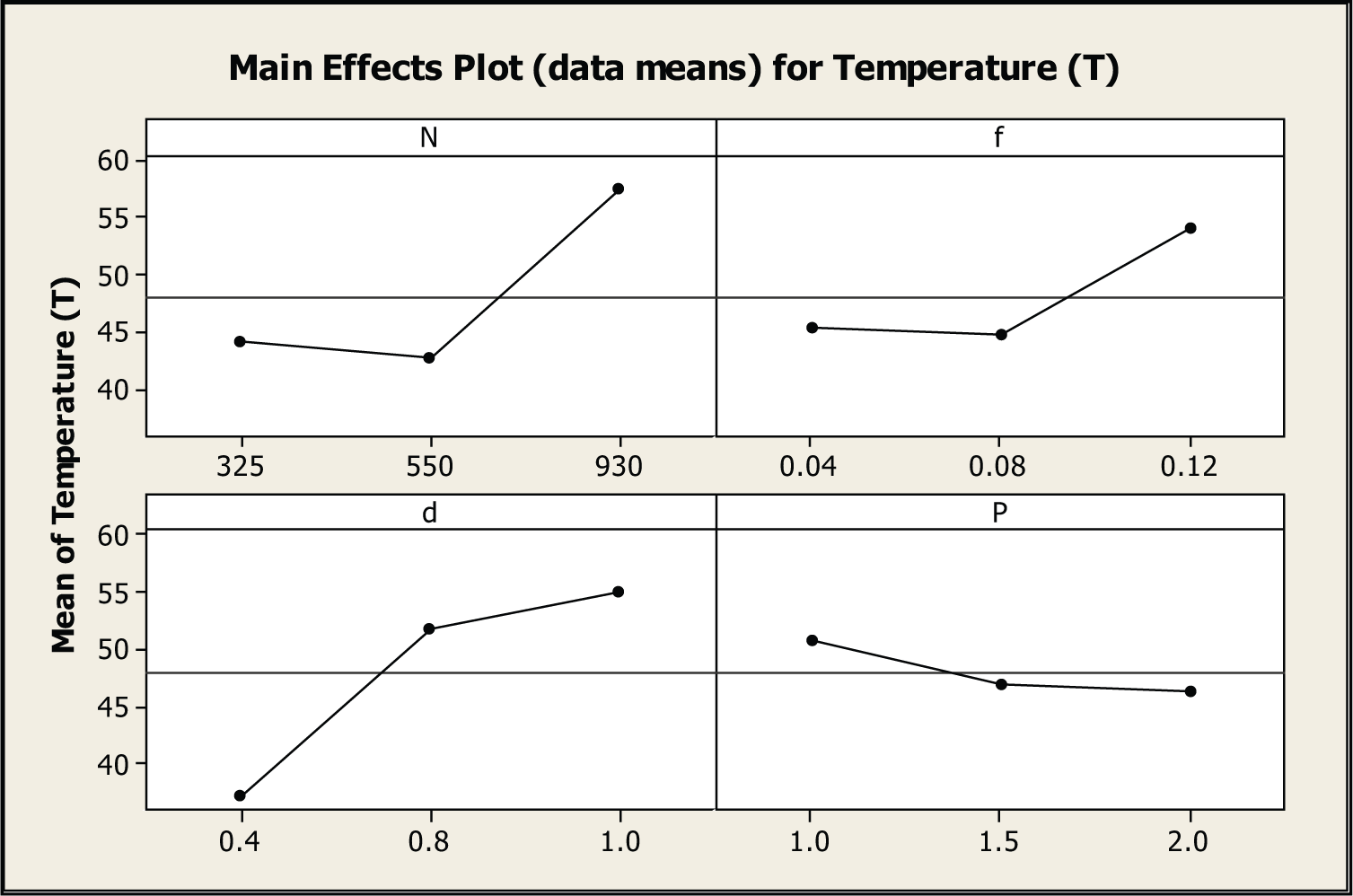
Main effect plot for temperature (T, °C).
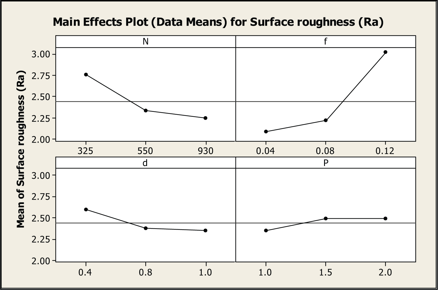
Main effect plot for arithmetic surface roughness average (Ra, µm).
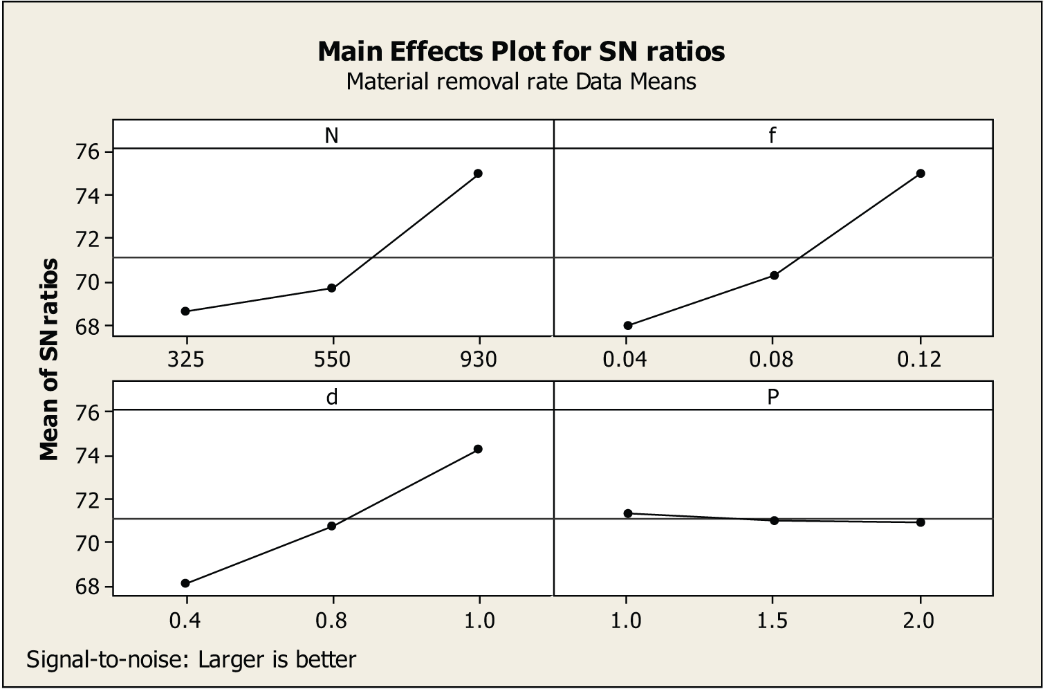
Main effect plot for material removal rate (mm3/min).
1. In Figure 2, the main effect plot for temperature (T) depicts the effect of each turning parameters. From Figure 2, it reveals that with the change in spindle speed (N) from 325 to 550 r/min, cutting temperature (T), that is, at chip–tool interface increases and maximum (57 °C) at 930 r/min. A similar trend is followed when feed (f) varies from 0.04 to 0.12 mm/rev as well as for DoC (d), it increases from 0.4 to 1 mm. But as pressure (P) increases from 1.0 to 1.5 bar and then to 2.0 bar, cutting temperature (T) reduces drastically below the mean line. It is found that at constant pressure (P) for each level (1.0, 1.5 and 2.0 bar) with varying spindle speeds (325, 550 and 930 r/min), cutting temperature at chip–tool interface shows a decreasing trend for each levels of parameter (N). Also with varying feed rates (0.04, 0.08 and 0.12 mm/rev) and DoC (0.4, 0.8 and 1.0 mm), cutting temperature shows the same results under the application of supply of spray impingement cooling.
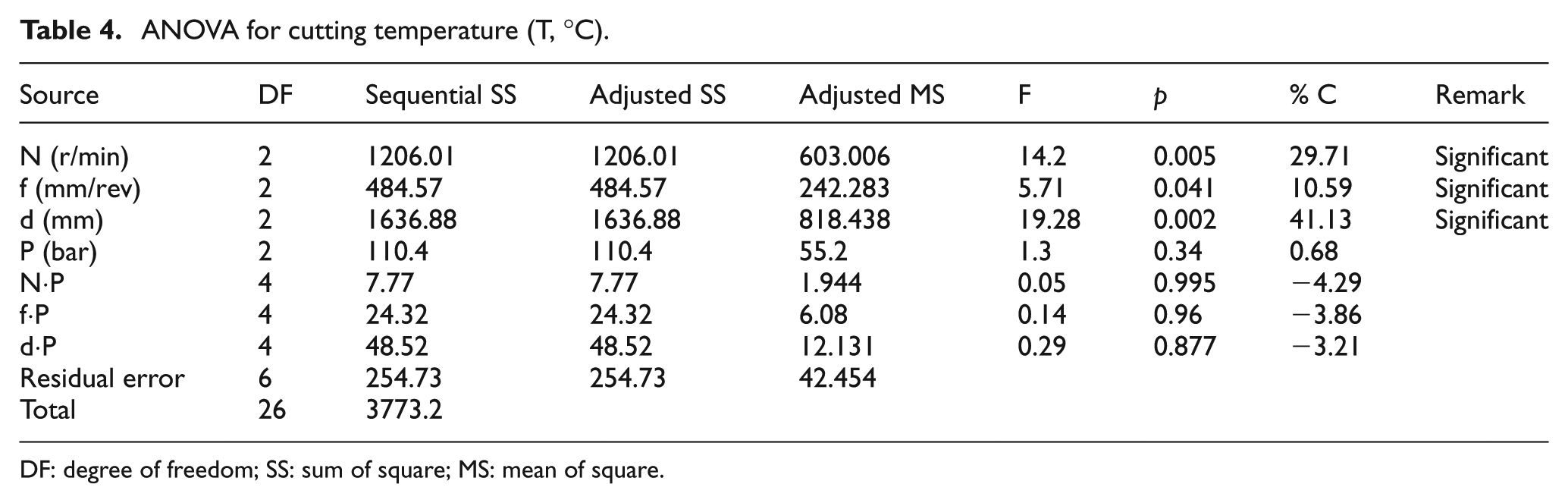
The result of the ANOVA for the cutting temperature is shown in Table 4. This analysis was carried out for a confidence level of 95% (5% significance). Table 4 shows the percentage of each factor contribution (p %) on the total variation with F value, thus indicating the degree of significance on the response (T °C). The sources with a p-value (probability of significance) less than 0.05 are considered to have a statistically significant contribution to the responses. Table 4 shows that significant factor for each response which explains 29.71% of spindle speed, 10.59% of feed and 41.13% of DoC. DoC (d) has been found to be the maximum contribution followed by spindle speed (N) and feed rate (f). Air pressure (P) and interaction (N-P, f-P, d-P) have much lower contribution.
ANOVA for cutting temperature (T, °C).
DF: degree of freedom; SS: sum of square; MS: mean of square.
2. As spindle speed increases from 325 to 550 r/min, arithmetic surface roughness value decreases, and with further increase in spindle speed of 930 r/min, it achieves smallest roughness value. This may be attributed due to the absence of built-up edge (BUE) formation at higher cutting speed and consequently, surface quality increases. At larger feed rate from 0.04 to 0.12 mm/rev, surface roughness average shows poor surface finish (Figure 3). At higher feed, the cutting tool traverses too rapidly on the workpiece and increases the chatter. This leads to the development of poor surface finish on the workpiece. With the varying DoC (d = 0.4, 0.8 and 1.0 mm) and air pressure (P), surface quality improves very well. At constant pressure (P) of each level, that is, at 1.0, 1.5 and 2.0 bar with varying spindle speeds (N), surface quality improves. As the feed rate (f) increases from 0.04 to 0.08 mm/rev and to 0.12 mm/rev with the same constant pressure, there is the rise in surface roughness (Ra) value for p = 1.0, 1.5 and 2.0 bar, respectively. Also with the DoC, surface roughness value increases at lower DoC and decreases at higher DoC. With constant values of feed rate and DoC at varying air pressure, surface roughness increases.
Table 5 shows the significant cutting factor for arithmetic surface roughness average (Ra). Feed rate (f) has the highest contribution of 38.15%. Spindle speed, DoC, air pressure and all interaction terms are statistically insignificant from the ANOVA study.
ANOVA for surface roughness (Ra, µm).
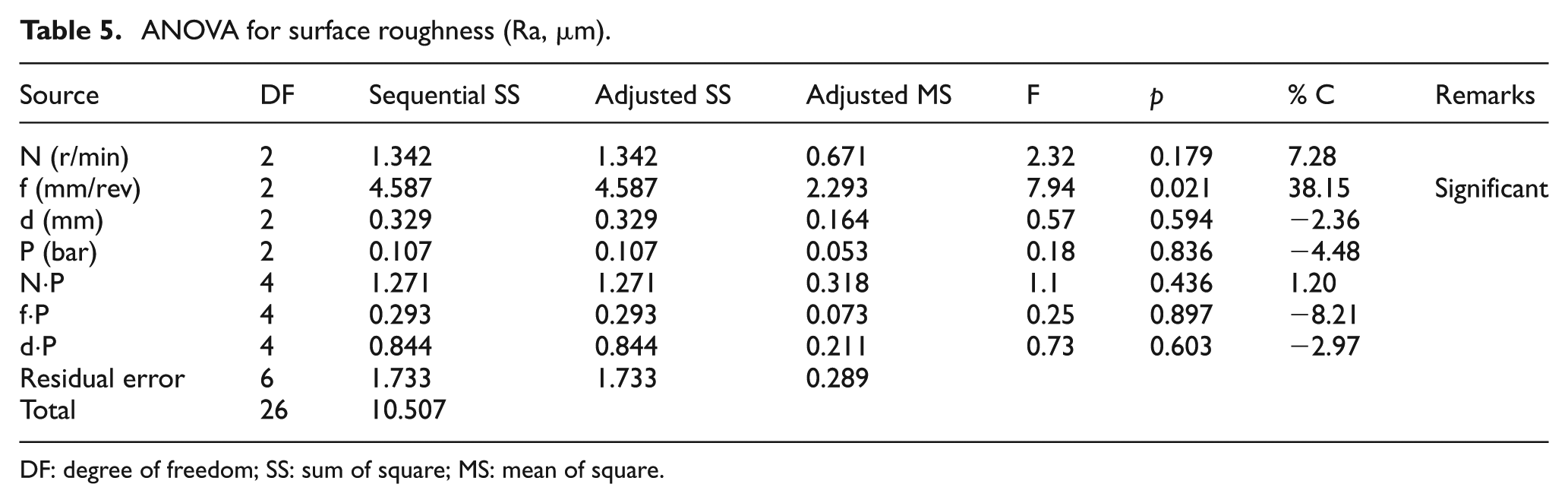
DF: degree of freedom; SS: sum of square; MS: mean of square.
3. Due to the temperature generation at the chip–tool interface, some amount of heat is transferred to the workpiece that softens the material shear strength and improves the material removal. Machining time was calculated by the relation 31
where t is machining time (min), L is machining length (mm), f is feed rate (mm/rev) and N is spindle speed (r/min).
The MRR for various cutting conditions was calculated (mm 3 /min) and shown in Table 3. By the relation from Tamizharasan et al. 32

where MRR is material removal rate (mm3/min) and V is volume of material removed (mm3).
In the MRR analysis, S/N ratio is calculated taking larger-the-better relationship. The effects of each cutting parameters on MRR are presented in Figure 4 and Table 6. From the analysis, it is clear that with the increase in spindle speed, feed rate and DoC, MRR is more as compared to the supply of air pressure (P) through spray impingement cooling. For individual constant pressure (P = 1.0, 1.5 and 2.0 bar) at each level with varying spindle speed (N), feed rate (f) and DoC (d), MRR for AISI 1015 is high.
ANOVA (larger is better S/N ratio) for material removal rate (mm3/min).
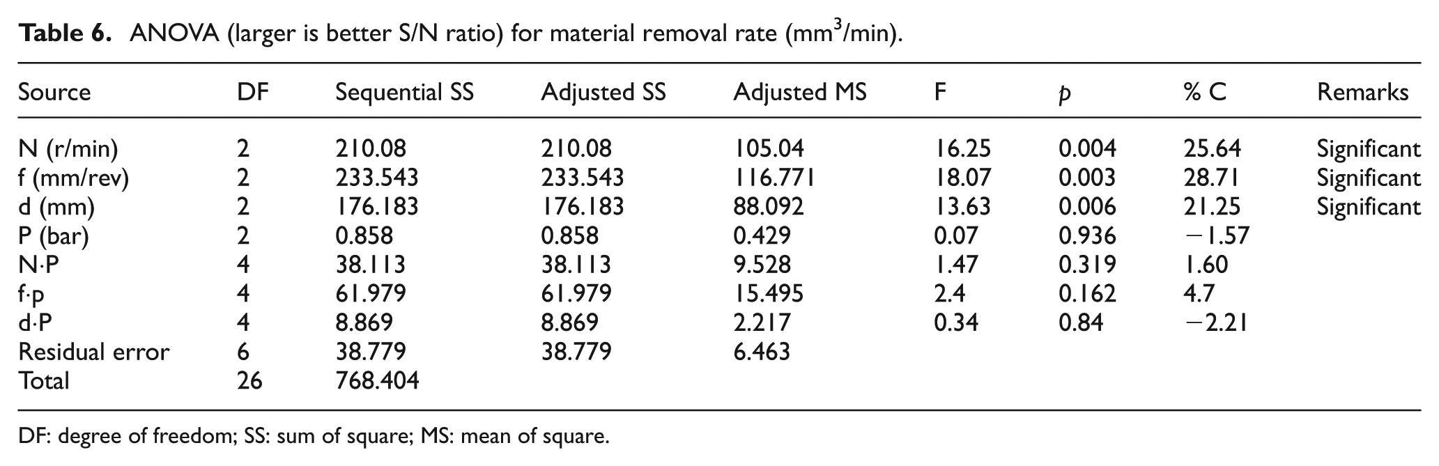
DF: degree of freedom; SS: sum of square; MS: mean of square.
From ANOVA of S/N ratio (Table 6) for MRR, feed rate is found to be most significant factor (28.71%) followed by spindle speed (25.64%) and then DoC (21.25%). Interactions of N-P, d-P, f-P, feed rate–air pressure (f-P) gives the contribution, that is, 4.7% and found to be insignificant as its p-value is greater than 0.05.
Comparison test
For comparisons between the performances of spray and dry cutting environment, the experiment has been performed as per Taguchi L9 orthogonal array, as shown in Table 7. Table 7 represents the variation in cutting temperature, arithmetic surface roughness average and MRR during hard turning of AISI 1015 steel with carbide insert with varying spindle speeds, feed rates and DoCs under spray impingement cooling and dry cutting environment. It is observed that the cutting temperature is less for spray impingement cooling compared to dry cutting. Spray impingement allows the cutting fluid to penetrate at the elastic contact zone (chip–tool interface) by capillary action; cooling occurs by convective as well as evaporative heat transfer mode. Reduction in cutting temperature and BUE formation resulted in better surface finish in spray impingement cooling environment. Surface roughness is observed to be better in spray cooling compared to dry cutting environment. However, their differences are very minimal for both cutting environments.
Experimental results as per L9 orthogonal array between spray impingement and dry cutting.
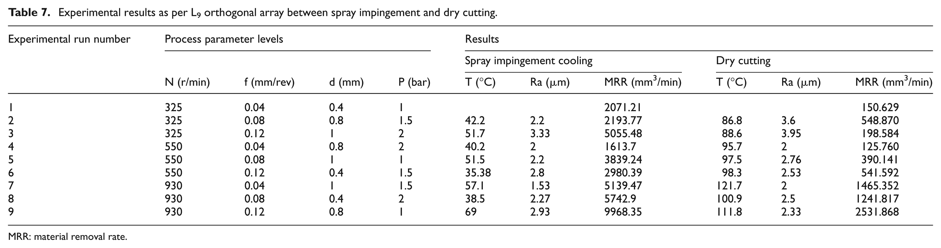
MRR: material removal rate.
The surface roughness value varies from 1.53 to 3.33 µm for spray impingement cooling, whereas it varies from 2 to 3.95 µm in dry environment. Thus, spray impingement has marginal effect on surface roughness of AISI 1015 through cemented carbide tool SNMG 120408. From Table 7, it indicates that the volume of material removed per min (MRR) in case of spray impingement is maximum with respect to spindle speed, feed rate and DoC. The infrared view of cutting temperature for spray impingement cooling and dry cutting is shown in Figures 5 and 6. These figures reveal the comparison of cutting temperature between spray cooling and dry cutting, and spray cooling appears to be better compared to dry cutting operation.
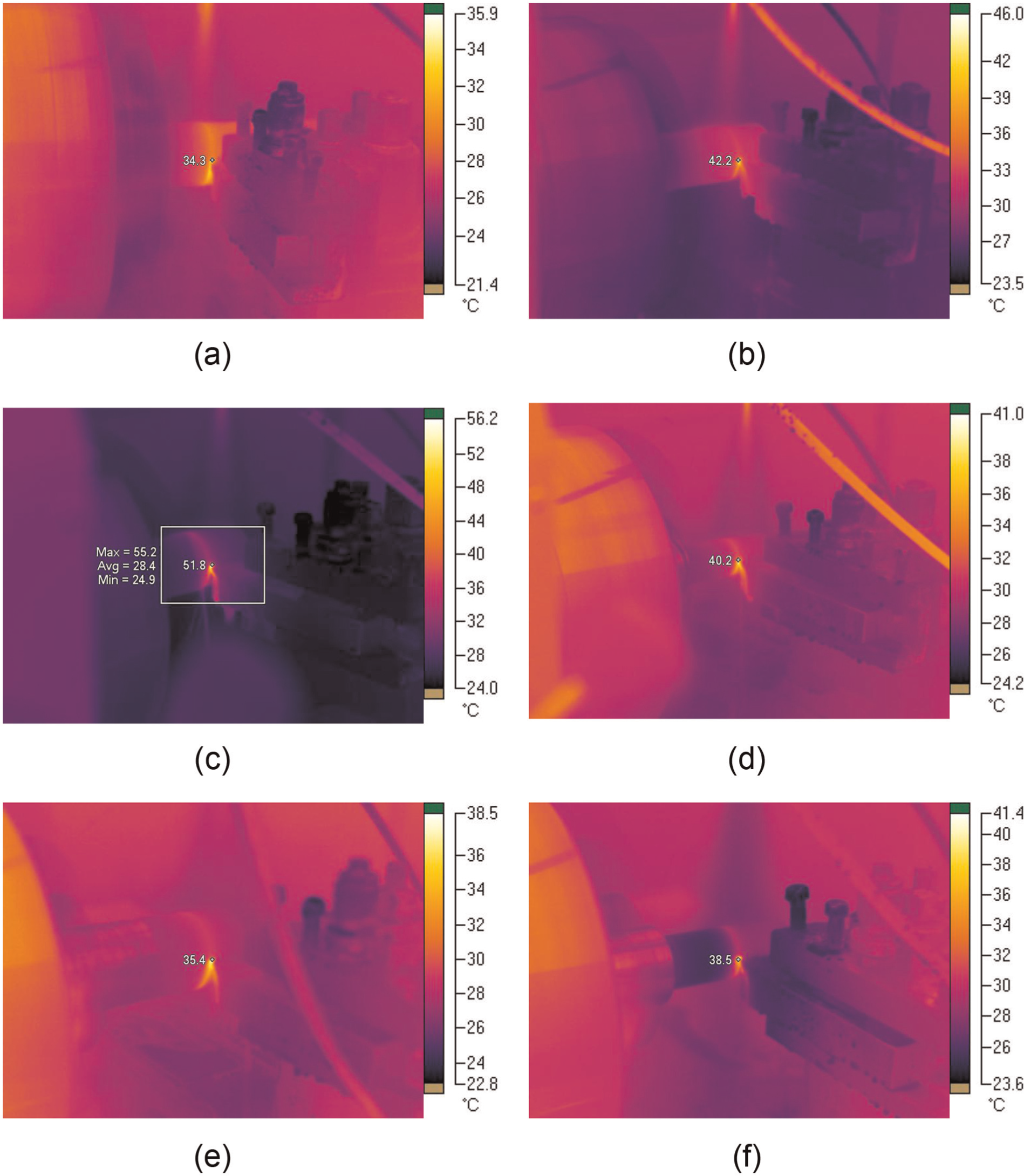
Infrared view of cutting temperature for spray impingement cooling at (a) 34.3 °C, (b) 42.2 °C, (c) 51.8 °C, (d) 35.4 °C, (e) 35.4 °C and (f) 38.5 °C.
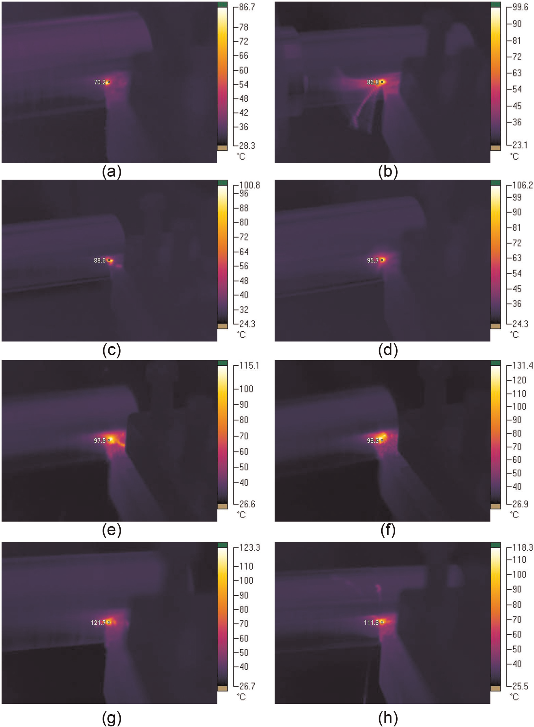
Infrared view of cutting temperature for dry cutting at (a) 70.2 °C, (b) 86.8 °C, (c) 88.6 °C, (d) 95.7 °C, (e) 97.5 °C, (f) 98.3 °C, (g) 121.7 °C and (h) 111.8 °C.
Optimality test
For comparison test results as per Taguchi L9 orthogonal array, it is found that spray impingement cooling shows the best result than the dry cutting in terms of all responses investigated. It is also observed that the arithmetic surface roughness average has marginal effect on spray cooling and gives approximate result as in dry cutting. Hence, optimality test (multi-response parametric optimization) has been performed for spray impingement cooling (Table 7) only as it outperforms dry cutting.
Grey relational analysis for turning is the multi-response optimization technique in which multi-responses can be converted into optimization of single grey relational grade (GRG). In this, experimental responses (cutting temperature, arithmetic surface roughness average and MRR) are normalized in the range between 0 and 1 called the grey relational generation. Next, the grey relational coefficient is calculated from the normalized experimental data to express the relationship between the desired and actual experimental data. After that, GRG is calculated by average of grey relational coefficient corresponding to each process response. Optimization of a cutting parameter is the level with the highest GRG. 33
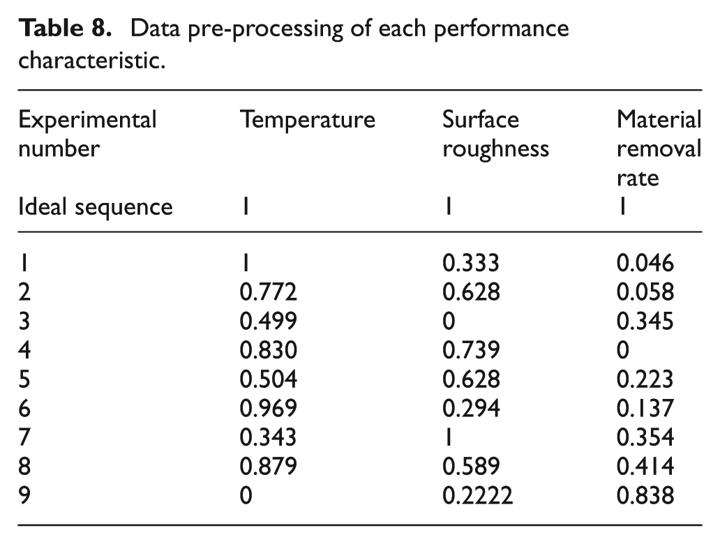
In this experimentation, linear data pre-processing method, 34 smaller-the-better is used for cutting temperature and arithmetic surface roughness average to get grey relational generation. This is expressed as

For MRR, higher-the-better characteristics is used and expressed as

where xi(k) is the value after the grey relational generation, min yi(k) is the smallest value of yi(k) for the kth response and max yi(k) is the largest value of yi(k) for the kth response. An ideal sequence is x0(k) (k = 1, 2, …, 9) for all responses in the study
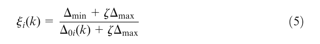
Table 8 shows the sequence after the grey relational generation. Next is to calculate grey relational coefficient. The purpose is to show the relational degree between the nine sequences x0(k) and xi(k), i = 1, 2, …, 9; k = 1, 2, …, 9. The grey relational coefficient can be calculated as
Data pre-processing of each performance characteristic.
where
The grey relation coefficient results for the experimental layout are shown in Table 9. The GRG can be calculated by averaging the grey relational coefficients; the GRG
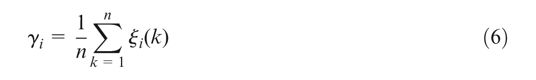
Grey relational coefficient of each performance characteristic.
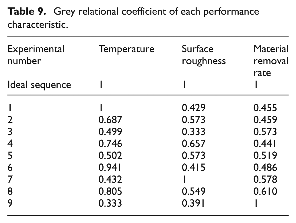
where n is number of responses.
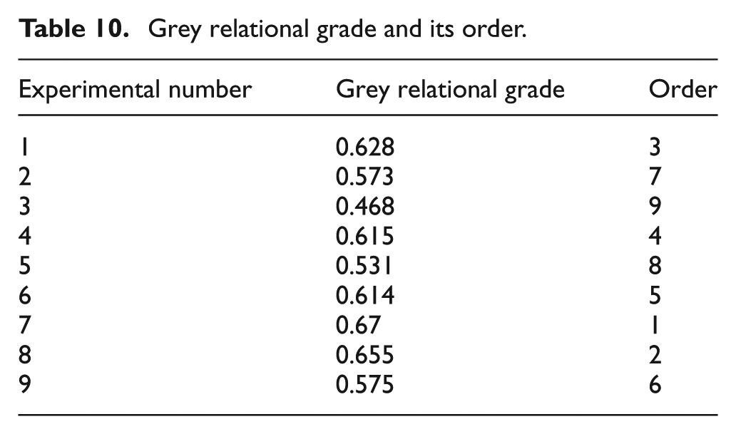
Table 10 shows the GRG. Higher value of GRG
35
represents stronger relational degree between the reference sequence
Grey relational grade and its order.
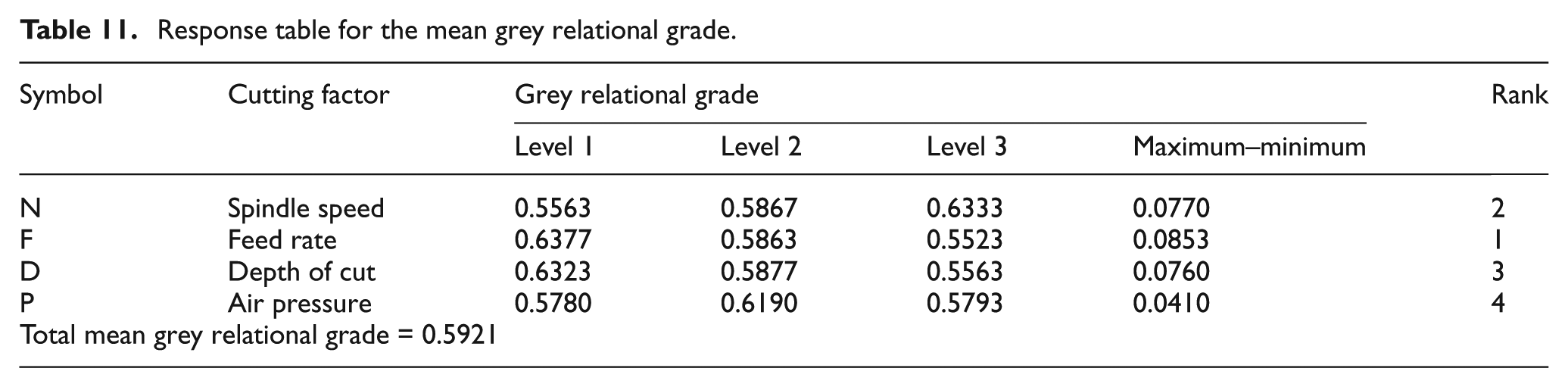
Response table for the mean grey relational grade.
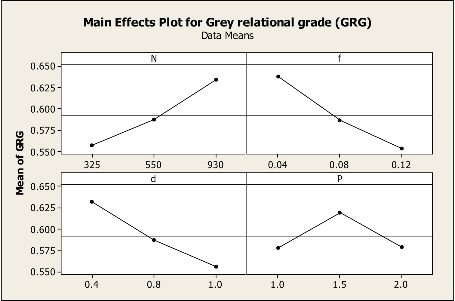
GRG graph.
Conformity test
After the optimal levels of cutting parameters are selected, the next step is to predict the performance characteristic and to find the improvement using the optimal level of cutting parameters. The estimated GRG

where
Table 12 shows the result of the confirmation experiment using optimal cutting factors. The results show that cutting temperature is decreased from 51.7 °C to 38.7 °C, surface quality improves to a great extent from 3.33 to 1.8 µm and more MRR is found between initial cutting factors (5055.48 mm3/min) to that of optimal cutting factors (6803.512 mm3/min). Thus, it is found that there is a good agreement between predicted (0.746) and experimental results (0.757) of GRG. The improvement in GRG from initial cutting factors (N1-f3-d3-P3) and optimal cutting factors (N3-f1-d1-P2) is found to be 0.288.
Results of cutting performance using the initial and optimal cutting factors.
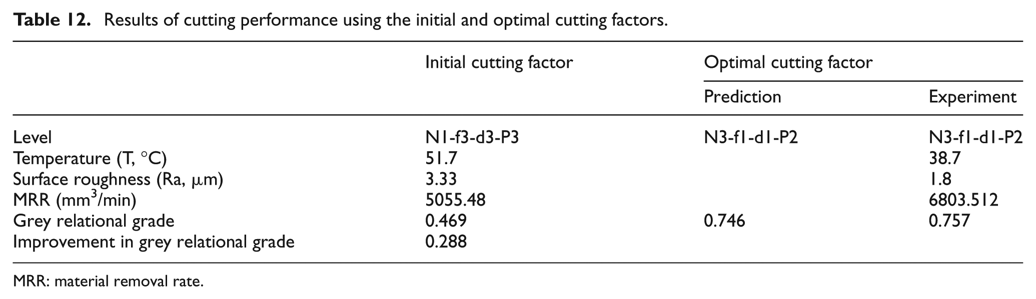
MRR: material removal rate.
Conclusion
In this work, Taguchi L27 orthogonal array is used to identify the main and the interaction effects of different factors, which include spindle speed, feed rate, DoC and air pressure supplied by the spraying system on the response pattern. Comparison is made between dry cutting and spray impingement cooling with same combination under L9 orthogonal array. Finally, multi-response optimization is adopted. The following major conclusions may be drawn from the above analysis:
With increases in spindle speed, cutting temperature increases. A similar trend is observed when feed rate (0.04–0.12 mm/rev) and DoC (0.4–1 mm) vary.
ANOVA signifies maximum percentage of contribution of DoC (41.13%) followed by spindle speed and feed rate.
Feed rate is the only significant factor (p < 0.05, % C = 38.15) for surface roughness.
Material removal is maximum at N = 930 r/min, f = 0.12 mm/rev, d = 0.8 mm and P = 1.5 bar. Feed rate plays the most significant factor followed by spindle speed and DoC.
Spray impingement cooling appeared to be effective compared to dry cutting.
From mean GRG, optimal parametric combination is found to be N3-f1-d1-P2, that is, spindle speed of 930 r/min, feed rate of 0.04 mm/rev, DoC of 0.4 mm and air pressure of 1.5 bar.
The improvement in GRG from initial cutting factor (N1-f3-d3-P3) to optimal cutting factor (N3-f1-d1-P2) is found to be 0.288. Thus, performance characteristics are greatly improved.
Footnotes
Acknowledgements
The authors would like to thank the School of Mechanical Engineering, KIIT University, Bhubaneswar, Odisha, India, for helping and carrying out experiment and measurement works.
Declaration of conflicting interests
The authors declare that there is no conflict of interest.
Funding
This research received no specific grant from any funding agency in the public, commercial or not-for-profit sectors.