
Abstract
Surfactant and graphite powder–assisted electrical discharge machining was proposed and experiments were performed on titanium alloy in this investigation. Analysis was carried out to observe changes in dielectric fluid behaviour, material removal rate, surface roughness, recast layer thickness, surface topography and energy-dispersive X-ray spectroscopy. It was found out that the addition of surfactant to dielectric fluid (electrical discharge machining oil + graphite powder) improved the material removal rate and surface roughness. It was noticed to have reduced the recast layer thickness and agglomeration of graphite and sediment particles. Biface material migrations between the electrode and the workpiece surface were identified, and migration behaviour was powerfully inhibited by the mixing of surfactant. Surfactant added into dielectric fluid played an important role in the discharge gap, which increased the conductivity, and suspended debris particles in dielectric fluid reduced the abnormal discharge conditions of the machine and improved the overall machining efficiency.
Keywords
Introduction
Titanium alloy is widely used in various fields such as aerospace, automobile, chemical and biomedical fields due to its prominent properties like high strength-to-weight ratio, high temperature stability and exceptional corrosion resistance. Machining of titanium alloy is a very difficult and expensive process, and to overcome these technical difficulties, Electrical Discharge Machining (EDM) is widely used. 1 EDM is a non-conventional thermoelectric process for machining hard metals and alloys. It has the ability to machine conductive materials irrespective of their mechanical and chemical properties. It has been widely used for producing dies, moulds and finishing parts for aerospace, automotive and surgical components. 2
In the EDM process, electrical discharge occurs between the electrode and the workpiece. The workpiece is held by positioning to a fixture with a discharge gap between the workpiece and the electrode that are submerged in a dielectric fluid. When pulsating direct current (DC) power supply is turned on, voltage pulses will be transformed into electrical sparks. These sparks will then be passed on to the electrode and to the workpiece through the discharge gap. The DC Servo controller mechanism stabilizes the spark gap distance, and discharge current condition generates the spark and is transferred to the workpiece wherein high temperature is produced in the machining zone. This results in melting more amount of material and is flushed along with the debris and tar particles with the dielectric fluid, but some amount of material will re-solidify on the metal surface. As the dielectric fluid concentration increases, the sedimentation of the particles concentration increases, due to which more debris and tar particles are agglomerated on the machined workpiece surface. This makes the machine unstable, degrades the material removal rate (MRR) and increases the surface roughness (SR). On the workpiece surface, unwanted defects such as cracks, porosity and improper recast layer are formed. 3
Thus, a comprehensive study to improve the machining efficiency of EDM is to be carried out using the titanium alloy. Past researchers have approached different techniques and various conditions such as ultrasonic vibration-assisted electrical discharge machining (UAEDM), gas-assisted electrical discharge machining (GAEDM), cryogenic cooling–assisted electrical discharge machining (CAEDM), powder-mixed electrical discharge machining (PMEDM), rotary-assisted electrical discharge machining (RAEDM) and magnetic-assisted electrical discharge machining (MAEDM). But the literature on the study of the effect of graphite powder and surfactant-mixed dielectric fluid on the machining characteristics of titanium alloy is very limited.
Additives like graphite powder and surfactant were added into the dielectric fluid for better circulation in the discharge gap and to avoid the particle agglomeration.4,5 During the machining process, particles entering the discharge gap, breakdown the voltage easily, which reduces the insulating strength by increasing the discharge gap and passage discharges are also evenly distributed during the entire machining process. As a result, the process becomes more stable, thereby improving the machining efficiency, which lowers the SR and increases the MRR.
For instance, Jeswani 6 studied the effect of the addition of graphite powder to kerosene, used as the dielectric fluid during the EDM. It is observed that adding graphite powder to kerosene changed the ionization–deionization characteristics of the liquid to permit more spark discharges per unit time. The reduction in the breakdown voltage results in a higher discharge frequency which in turn increases the MRR. Chow et al. 7 investigated the micro-slit operation on Ti-6Al-4V with a modified rotary disc copper electrode and addition of Al and SiC powders separately in kerosene as dielectric in the EDM process. The negative polarity was used. It has been observed that the gap between the electrode and the workpiece increased slightly due to the addition of powders. This increases the MRR and disperses several discharges in several increments due to which the particle size of debris is reduced so that they are removed easily with the increase in SR. The MRR is more when SiC is added to kerosene than aluminium. Kibria et al. 8 compared the effect of various dielectrics such as kerosene, de-ionized water and mixing boron carbide (B4C) powder with kerosene and de-ionized water during micro-hole machining of Ti-6Al-4V using EDM. It has been noticed that MRR and tool wear rate (TWR) are more using de-ionized water than using kerosene. When B4C powder-mixed dielectrics are used, the MRR increases with de-ionized water, but the TWR decreases with kerosene. It has also been observed that the recast layer thickness (RLT) is less in the case of de-ionized water compared to kerosene. Dong et al. 9 studied the application of orthogonal experiment in EDM using the suspended powder fluid. Cr12MoV was employed as a workpiece and copper was used as electrode with positive polarity. Kerosene mixed with Al powder was used as a dielectric. As the powder concentration is increased, MRR increases and SR decreases. Kun Lin Wu et al. 10 studied an experimental investigation of the surfactant mixed with EDM for SKD 61steel. Parameters such as peak current, pulse duration, open voltage and gap voltage were changed to explore their results of the addition of surfactant to dielectric fluid which increases conductivity and machining efficiency. It is observed that MRR is higher in the case of Span 20 than Span 80. The maximum MRR is obtained with Span 20 of concentration 30 (g/L). This MRR is 40% higher than that of pure kerosene without affecting the SR much.
Wu et al. 11 investigated the improvement of surface finish on SKD 61steel using EDM with three dielectrics: pure kerosene, aluminium powder added kerosene and kerosene with aluminium powder and surfactant added dielectric. It was concluded that the insulation is lowered and the gap distance between electrodes is increased with the Al powder and surfactant added dielectric. The thin optimized recast layer can be achieved when the dielectric is mixed with both aluminium powder and surfactant due to well-dispersed aluminium powder and uniform distribution of discharge energy during the EDM process. Dukhin and Goetz 12 conducted the experimental study of non-ionic surfactants and 5% Alumina AKP 30 added to non-polar liquids (kerosene). Span 20 and Span 80 surfactants were added to the water and kerosene, and it was observed that 5% alumina and Span 20 added to kerosene show better dispersion effect compared to Span 80. It was also concluded that two mechanisms are involved in this study: dissociation of the span molecules and apparent dissociation constant with hydrophilic–lipophilic balance (HLB).
Zhang et al. 13 presented a new process, water-in-oil (W/O) emulsion mixed with EDM, and considered the machining parameters, such as peak current, dielectric and pulse duration, and studied their effects on machining performance, such as MRR, SR and relative tool wear rate (RTWR). It was observed that increase in the MRR enhanced the relative electrode wear rate (REWR), due to the high viscosity of dielectric fluid which can restrict the expansion of the discharge channel; the impulsive force is acting on a mined area. They mentioned that when the discharge current is increased. MRR increases due to more discharge energy, and impulse forces act on the machined surface. Liu et al. 14 studied different dielectric fluids used in EDM and measured the characteristics of the recast layer and relationships of other machined parameters. It was observed that the recast layer formed in the W/O emulsion exhibited larger SR, thickness and micro-hardness compared to that formed in kerosene and de-ionized water.
Konig and Jorres 15 studied aqueous solutions of organic compounds as dielectric working media for die-sinking EDM. In this process, the dielectric was mixed with glycerine under the working conditions of discharge current, long pulse duration and high duty factor. It was concluded that tool electrode wear was reduced under the roughing conditions (high discharge current) which improved the machining conditions (MRR). When water is considered as the dielectric fluid, SR is lowered and the metal characteristics of the surface are degraded.
In this research, the influence of surfactant-mixed EDM of titanium alloy is studied. By varying surfactant concentration and keeping other parameters constant such as discharge current, pulse on time, pulse off time and duty factor, the MRR, SR and RLT are considered as the performance characteristics. Hence, further study has been carried out to observe the influence of process parameters on the presence of elements on the machined surface by energy-dispersive X-ray spectroscopy (EDX) and also to observe the surface topography using the scanning electron microscope (SEM).
Experimental work
The experiments were performed on a Formatics EDM 50 die-sinking machine mounted on a custom-built dielectric cycling system. The electrode is fed downwards under DC servo control into the workpiece. Spark Erosion 450 EDM oil and graphite powder particles are used as the dielectric fluid for machining, which are used in die-sinking machines for high machining speed and good surface finish. Surfactant is added in a certain amount into the dielectric fluid and continuously stirred in order to maintain uniform distribution. The homogenously mixed dielectric fluid is pumped into the machining region using side flushing. The surfactant chemical properties are presented in Table 1.
Span 20 surfactant properties.
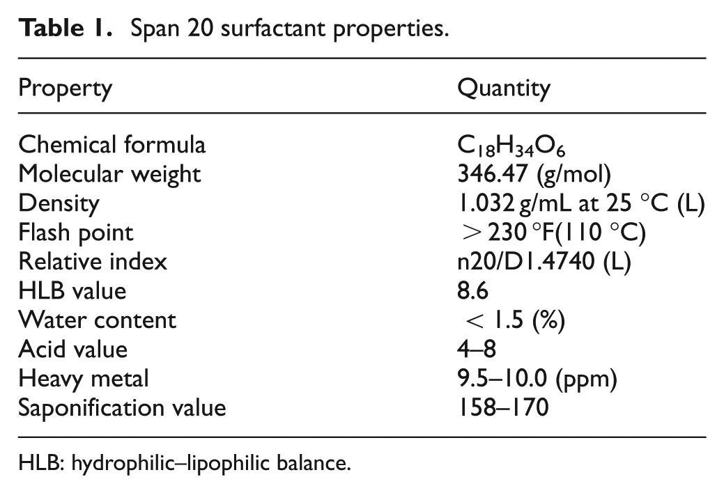
HLB: hydrophilic–lipophilic balance.
Experiments were conducted with a reverse polarity electrode. The electrolyte copper with dimensions of 14 mm diameter and 70 mm length was selected as an electrode. The workpiece with dimensions of 100 mm length, 50 mm width and 5 mm thickness was employed. Each experiment was conducted for 30-min duration. Prior to machining, the workpieces and electrode were cleaned and polished. The workpiece was firmly clamped in the vice and immersed in the dielectric fluid. The die-sinking EDM experimental set-up is shown in Figure 1, and titanium alloy workpiece properties are shown in Tables 2–4. The weight of the workpiece and the electrode tool was measured using a digital weighing balance (CITIZEN Scale India, Pvt Ltd, Hyderabad.) before and after the commencement of machining to calculate the MRR and TWR, respectively. The SR of the machined workpieces was measured using Handysurf equipment. The ranges of each factor were taken based on the capability of the machine, and preliminary experiments were conducted on their performances effects. When straight polarity is used, the MRR is very low due to poor thermal conductivity and high electrical resistivity of workpiece (titanium alloy). This enhances the unstable erosion conditions like arcing, short circuit and so on. The preliminary experiment result shows that lower MRR is observed when straight polarity was used. Hence, this study is focussing on increasing the MRR of the workpiece using reverse polarity.16–20 When the discharge current was kept above 10 A, it was observed that the MRR was significant, and when more than 20 A current was selected, it resulted in higher MRR necessitating the selection of values. The range selected for the pulse-on time and pulse-off time is based on the pilot experiments and the literature. 20 The pilot experiments were carried out with the addition of graphite powder from 1 to 20 g/L into the dielectric fluid. The graphite powder morphology can be observed as shown in Figure 2. From Figures 3 and 4, the effect of graphite powder addition into the dielectric fluid on the MRR and SR can be observed. In Figure 3, it is indicated that the powder concentration of 14 g/L results in higher MRR due to the increasing conductivity of the dielectric fluid in the machining gap, which results in a series discharge effect as well as an even distribution of discharge energy in the machining gap. 21 Figure 3 depicts that 14–16 g/L graphite powder concentration added into the dielectric fluid reduces the SR at a slow rate due to reducing the diameter and depth of craters of the material.21–23 Although graphite powder concentration of 16 g/L is added to dielectric, RLT is slightly increasing, as observed in Figure 5, as the presence of graphite powder particles within the discharge gap creates two opposing effects that affect the RLT. With the increase in powder concentration and resulting gap enlargement, the ease of plasma expansion lowers plasma over-pressure considerably and allows more molten material retentions. 24 Another possible cause is machining parameters, and the type of dielectric fluid also influences the thickness of recast layer.24,25 The quality and quantity of EDX analysis results of 14–16 g/L powder concentration samples are presented in Figure 6. From Figures 2 and 3, all the queries asked by the reviewer are addressed. Hence, for further experimentation, the graphite powder concentration is fixed at 14 g/L. The concentration of the surfactant was varied between 0.25 and 15.0 g/L, but the surfactant used above 10 g/L concentration did not show any considerable improvement in the performance characteristics. No effect on MRR and RLT was observed when 0.25–1 g/L surfactant concentration was added to the dielectric fluid; the reasons are mentioned below. The mixing of aromatic hydrocarbon (surfactant) with EDM oil dielectric fluid consisting of open-chain aliphatic hydrocarbon has a distinct influence on the ignition and breakdown phase of single discharges. Particularly, the non-polar (like EDM oil) group and -I-substituted aromatic compounds caused average fast ignition at lower voltages. These conditions are particularly desired during the finishing of surfaces with a lower roughness and small thermal affected zone. The aromatic compounds are easily dissolved and dispersed into the dielectric fluid and also react more strongly to electron transfer reactions. The developing charges are effectively stabilized by delocalization. The ionization potentials could also be decreased by substituents, and generation is forced by ion exchange. 26
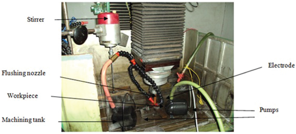
Modified experimental set-up.
Experimental settings.
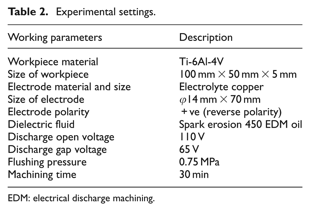
EDM: electrical discharge machining.
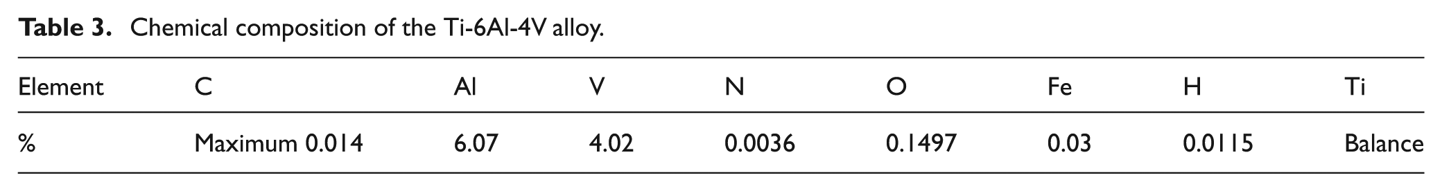
Chemical composition of the Ti-6Al-4V alloy.
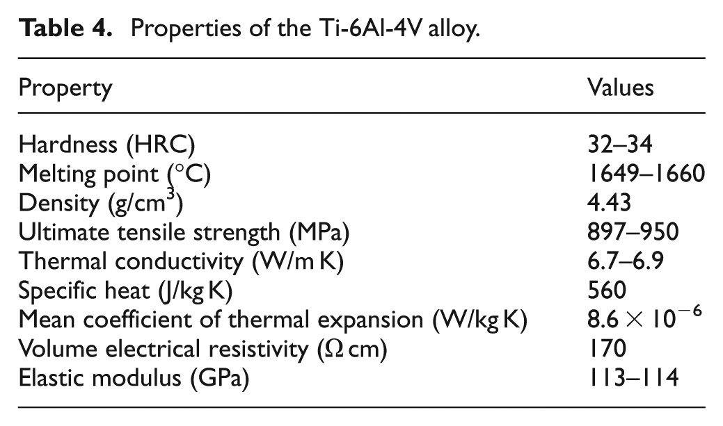
Properties of the Ti-6Al-4V alloy.
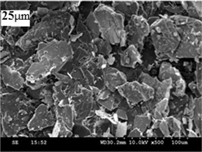
SEM morphology of graphite powder particles (µm).
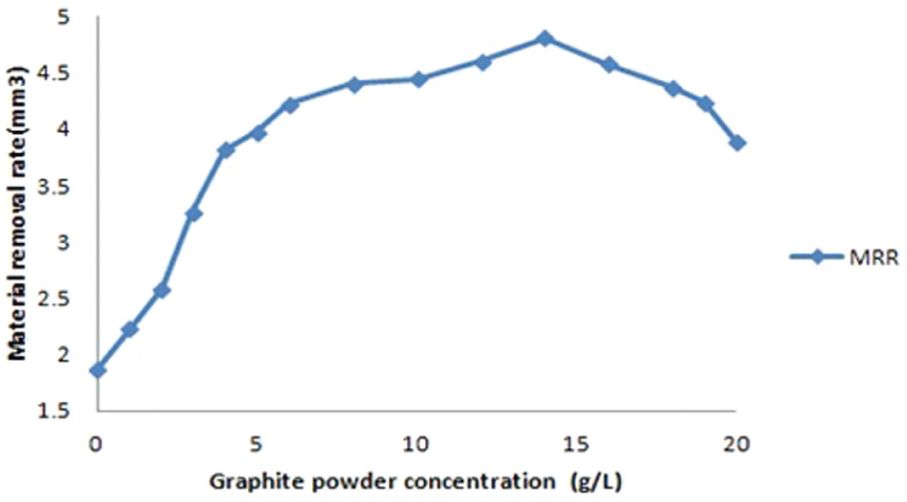
Material removal rate versus graphite powder concentration.
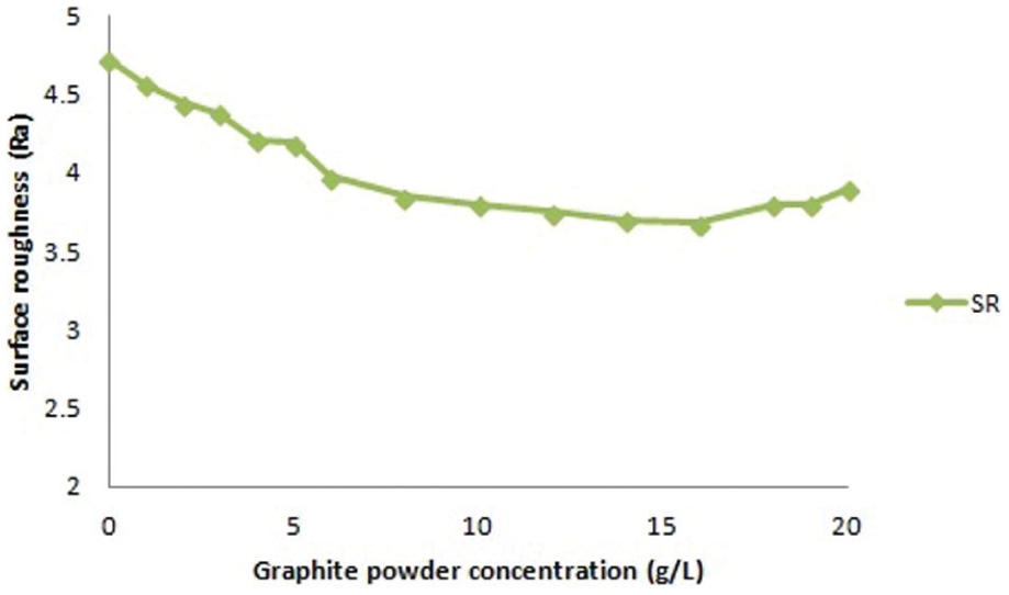
Surface roughness versus graphite powder concentration.
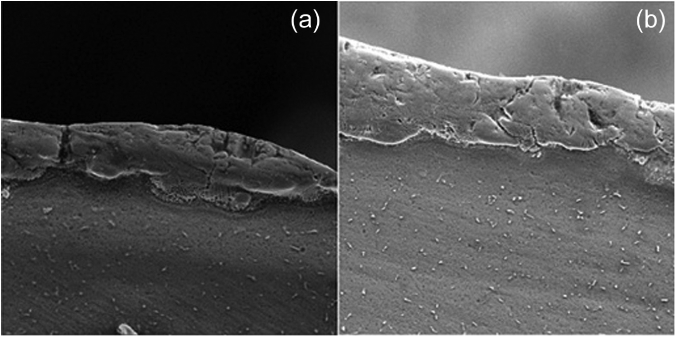
SEM micrographs of the EDMed RLT samples (a) Gr powder 14 g/L + EDM oil and (b) Gr powder 16 g/L + EDM oil.
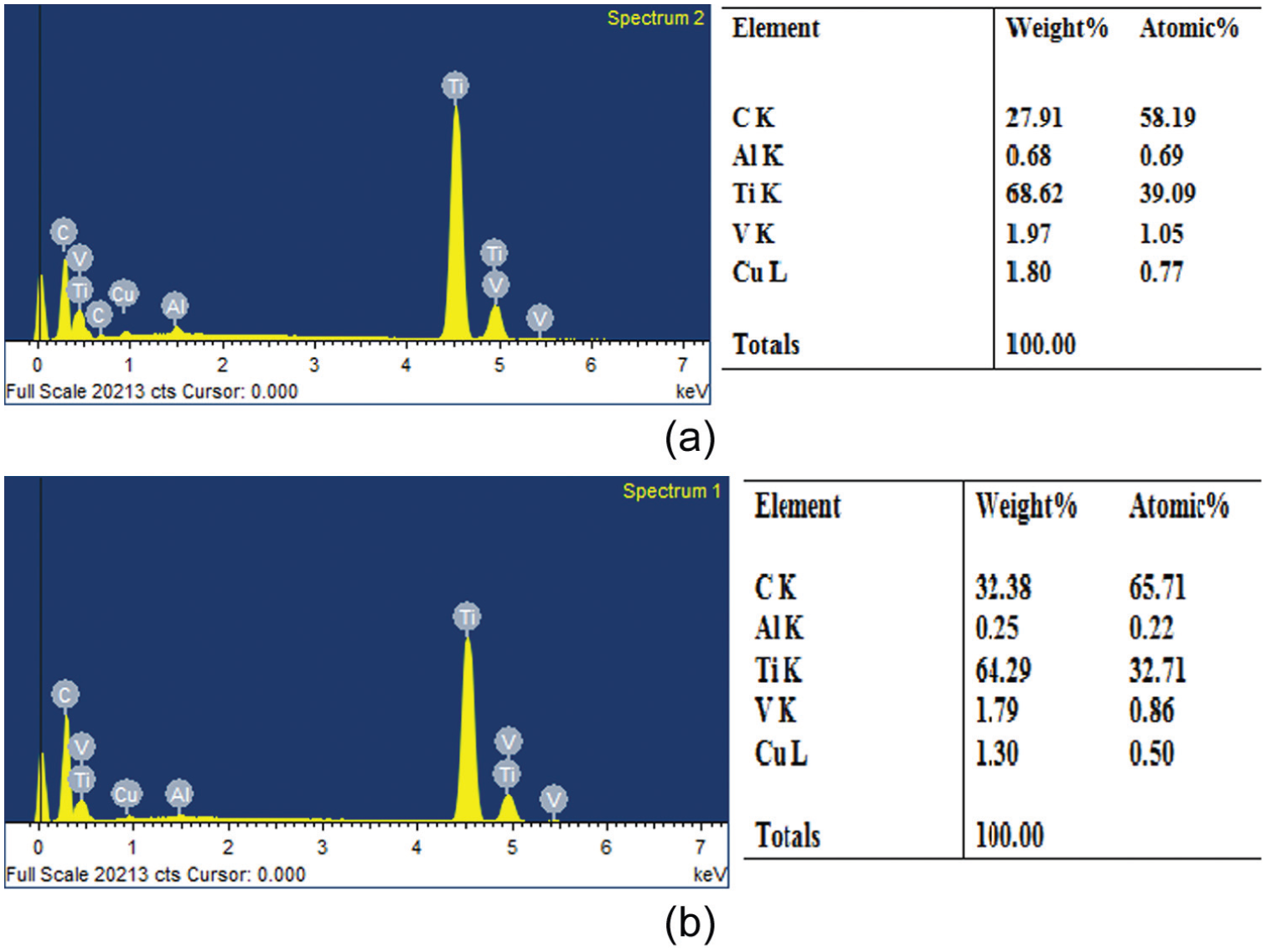
EDX analysis of the machined samples of (a) Gr powder 14 g/L + EDM oil and (b) Gr powder 16 g/L + EDM oil.
Equal dispersion of graphite particles and surfactant in the dielectric fluids can be stabilized by stirrer and in the absence or presence of electrical barriers. Such barriers can be produced by the surfactant molecules (lyophilic chains) adsorbed on the surface of the powder particles extended into the dielectric phase and interact with each other (surfactant + powder particles + dielectric). If the surfactant head group is of the same charge as that of the substrate, electrostatic repulsion may oppose adsorption. If the head groups are of the opposite sign to that of the surface, adsorption may be enhanced. The adsorption depends on the magnitude of the hydrophobic bonding free energy; the amount of surfactant adsorbed increases directly with the increase in the alkyl chain length in accordance with the trouble created.4,5,27
Low concentration of organic compounds used in the dielectric fluid causes an increase in conductivity, and equal discharge energies formed on the working gap result in lower SR and nominal MRR. The MRR increases when the organic compound concentration as well as organic compound molecular weight increases (it is largest).15,28
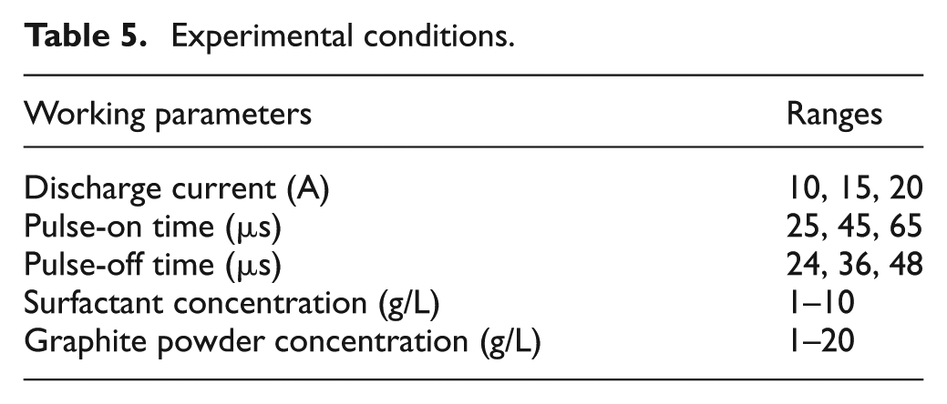
The experimental conditions are considered as mentioned in Table 5. Topographic observation through the EDM surfaces was performed using a VEGA3TESCAN (Tescan, Czech Republic) SEM. For microstructural observation, samples were prepared using conventional metallographic techniques on cross-sections; 94% distil water, 4% HNO3 and 2% HF acid mixture was selected as an etchant reagent based on its ability to etch the metal.
Experimental conditions.
Results and discussion
Dielectric fluid behaviour
To examine the effect of surfactant-mixed dielectric fluid behaviour (EDM oil + graphite 14 g/L) on EDM, a graphical representation was used to observe the discharge gap between the copper electrode and the titanium alloy. Figure 7 shows the graphical representation of dielectric fluid behaviour on EDM; Figure 7(b) represents surfactant-mixed dielectric fluid (surfactant 6 g/L + graphite 14 g/L + EDM oil) and Figure 7(a) without surfactant-mixed dielectric fluid (graphite 14 g/L + EDM oil). From Figure 7(b), it is clearly observed that the graphite powder particles were suspended in dielectric fluid due to surfactant addition compared to Figure 7(a), indicating that graphite particles are agglomerated in the dielectric fluid of EDM.
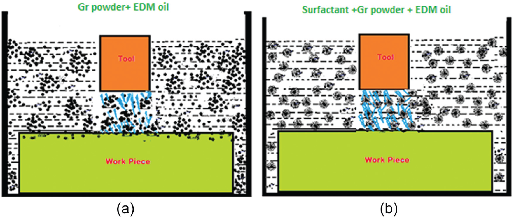
Dielectric fluid behaviour (a) Gr powder 14 g/L + EDM oil (b) Gr powder 14 g/L + EDM oil+ Surfactant 6g/L.
Based on the microstructural views, SEM observation, performing droplet size experiments related to dielectric fluid and also supported by the literature, Figure 7(b) was drawn. 29 Figure 7(b) shows that surfactant improved the surface tension of graphite particles, debris, carbon dregs and tars, and also increased the dispersion and dissolubility of particles, finally debris dispersed and deposited in the dielectric fluid.4,5
SEM micrograph and EDX results are shown in Figures 11 and 12 that further clarify the surfactant concentration effect on the migration of copper, oxygen and graphite. This result again shows that due to the surfactant and graphite mixture in the dielectric fluid, the dielectric characteristics are greatly improved and hence the machining characteristics of the titanium alloy are improved using EDM.
MRR
The MRR was measured by weight loss method and calculated from the volume of material removed from the workpiece at a particular time. Figure 8 shows that the MRR increases with the increase in surfactant concentration. The maximum MRR is found at the concentration of 6.0 g/L, and furthermore, the MRR reduced with an increase in surfactant concentration. Due to the surfactant added to the dielectric fluid, the conductivity of EDM oil increases, which results in shorter bridging time and improves electrical discharge efficiency, resulting in an increase in MRR. The addition of surfactant into the EDM oil retards the agglomeration of debris, carbon dregs and graphite powder particles due to electrostatic forces or van der Waal’s forces during machining. 10 Uniform distribution of graphite powder particles achieved in a discharge gap minimizes the bridge effect which causes better distribution of discharge energy resulting in an overall increase in MRR.
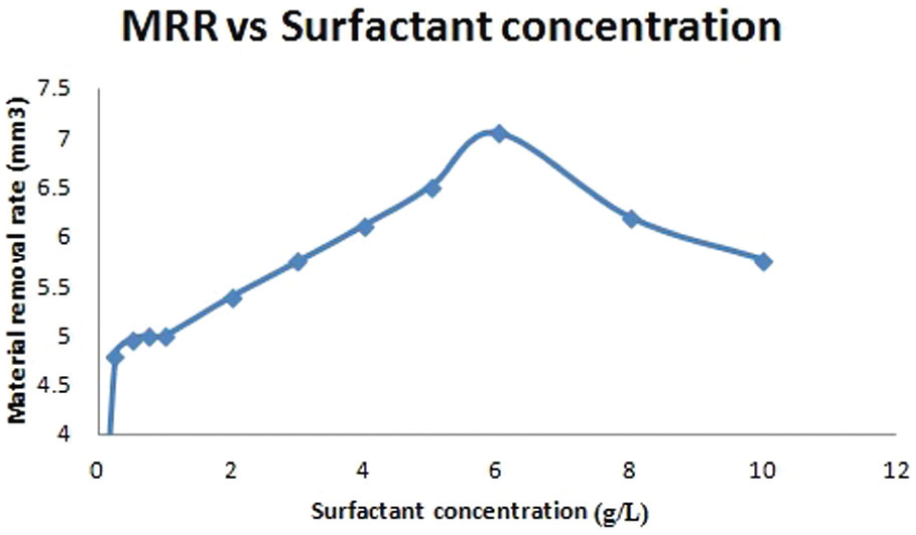
Material removal rate versus surfactant concentration.
The increase in surfactant concentration from 6 to 10 g/L decreases the MRR. This is due to increase in the conductivity of the dielectric fluid in the gap with an addition of surfactant to it. This results in the dissipation of more amount of energy into the dielectric fluid causing reduction in energy available at the workpiece, reducing the MRR. 30 The accumulated powder particles in the gap form a bridge in the discharge gap due to electrostatic and van der Waal’s forces between the electrodes, and the particles are unevenly distributed in the gap due to the addition of high surfactant concentration in the dielectric fluid. This leads to uneven dispersion of energy in sequential increments.
SR
The effect of surfactant concentration on the SR of the machined surface is shown in Figure 9. Under the graphite powder concentration of 14 g/L and when the surfactant concentration varies from 0.25 to 10 g/L, the SR tends to decrease precipitously at a surfactant concentration of .25 g/L and then increases slowly as the concentration increases further. Generally, an increase in the surfactant concentration in the dielectric fluid reduces the SR due to various reasons:
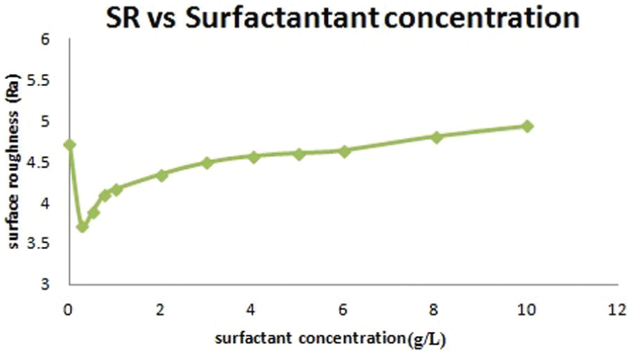
Surface roughness versus surfactant concentration.
Suitable amount of powder concentration, size and properties;
Well-distributed powder particles present in the machining zone;
Particularly, addition of graphite powder to the dielectric fluid results in an increase in conducting electrons and inversely reduces their electrical resistivity; 11
This in turn increases the overall conductivity of the dielectric fluid and decreases the dielectric strength of the working fluid, thus expanding the sparking gap; 26
The expanded sparking gap distance reduces the short-circuiting and arcing, which results in better surface finish at a lower concentration of surfactant and higher concentration of graphite.11,26
However, in this case, SR increases due to various reasons:
When surfactant concentration of the dielectric increases, the discharge energy and impulse force increase, and in turn the discharge current increases and more material will be removed to produce deeper and larger discharge craters. Deep and long micro-cracks are formed on the workpiece machined surface.
The surfactant concentration varies in the dielectric fluid, and the graphite powder particles along with the debris and carbon particles in the spark gap lead to an unstable and inefficient machining.
The surfactant concentration rises with an increase in the discharge gap, voltage and current. Due to this, more smoke is formed in the dielectric tank.
The overall electrical conductivity is increased drastically, and the dielectric strength is reduced considerably. This leads to short circuit, and the time available for ionization and de-ionization of gas in the plasma channel is insufficient.
The proportion of ions in the flow increases with the pulse duration time and surfactant concentration. Thus, the surfactant concentration, powder particles and ions strike the workpiece surface violently with higher impulsive force as negative polarity is employed. 26
RLT
RLT is a significant factor in the EDM process. EDM features such as large spark energy range, variation of surface finish, extreme cooling rates, chemical surface impurities from electrode and dielectric (carbon is a more important contaminant) and a recast layer attracted more attention for surface integrity of EDMed surfaces. The heat-affected zone produced by the EDM contains an upper layer known as white layer or recast layer followed by phase transformation zone and conversion zone.
Figure 10 depicts the sectional micrographs of the samples obtained in pure EDM oil (without powder and surfactant), with added powder (EDM oil and powder) and with added surfactant and powder in the dielectric fluid. From Figure 10(a) and (b), it can be observed that higher RLT is obtained. During the EDM process, higher sparking temperature (8000 °C −12,000 °C) of the machined surface is generated at the both the electrodes, which results in the formation of high amount of carbon and tar particles which reduce the conductivity of the dielectric fluid. 31 The particles are accumulated on the machined surface of the machined zone and these sediment particles cannot be easily removed from the zone, and these form an adhesive bonding with the work surface. These melted sediment particles form a thick layer on the workpiece surface. 16
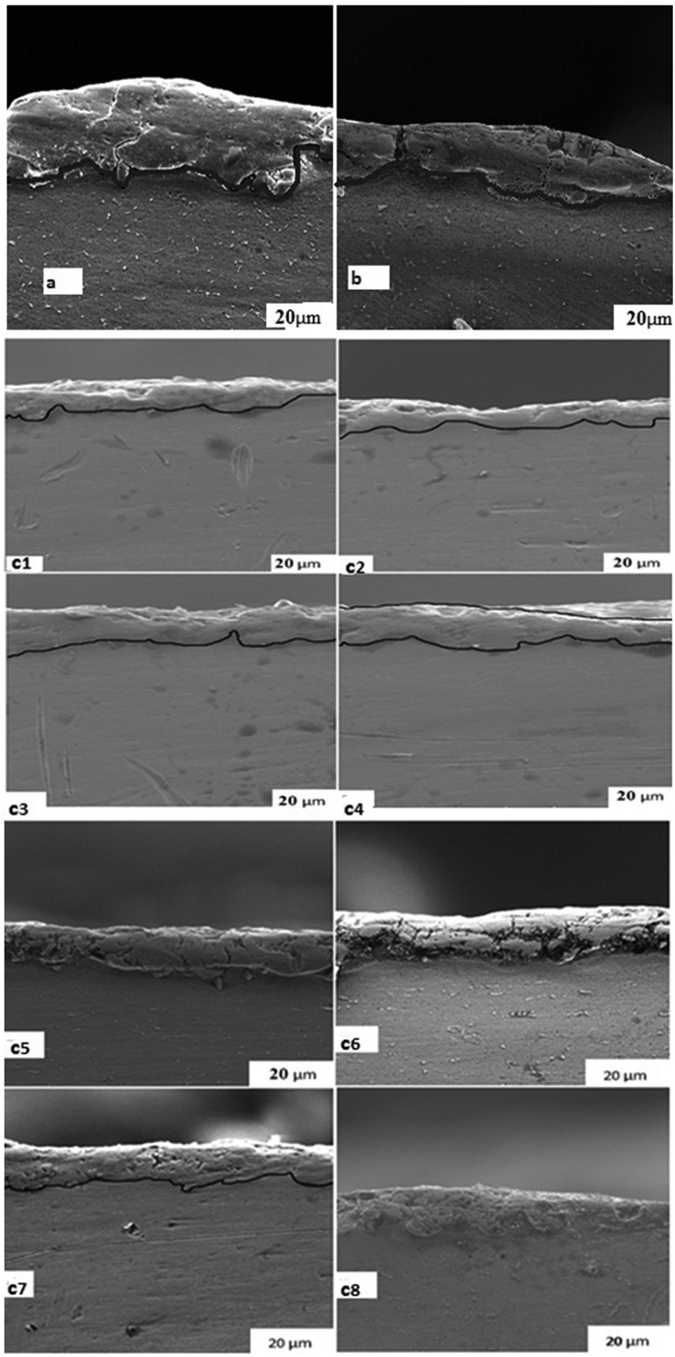
SEM micrographs of the EDMed RLT samples (a) Pure EDM oil, (b) without surfactant +Gr powder 14 g/L + EDM oil, (c) Fixed Gr powder 14 g/L + EDM oil+ Surfactant concentration vary (c1) 1 g/L, (c2) 2 g/L, (c3) 3 g/L, (c4) 4 g/L, (c5) 5 g/L, (c6) 6 g/L, (c7) 8 g/L and (c8) 10 g/L.
Figure 10(c) shows various RLTs for different surfactant concentrations. The addition of surfactant in the dielectric fluid leads to an increase in the RLT on the machined surface. Low surfactant concentration results in the formation of undulating type of recast layer at the metal surface, and even layers are formed with an increase in the concentration of surfactant.
The addition of low concentration of surfactant into the dielectric fluid improves its conductivity and lowers its viscosity, resulting in an easier flow of dielectric into the inter-electro gap. Furthermore, an increase in the dreg removal rate leads to improved flushing conditions. At the same time, the addition of surfactant into the dielectric fluid results in uniform distribution of discharge energy and lowers the amount of penetrated heat energy into the work surface that reduces the thickness of the recast layer.
However, with the increase in surfactant concentration, there will be a slight increase in the thickness of the uniform layer. The increase in the surfactant concentration in the dielectric fluid leads to an increase in the following:
The overall concentration of dielectric fluid and its conductivity;
The discharges’ spark energy and its plasma zone;
High impulse forces and high stress;
Amounts of molten material removed.
SEM micrograph
Figure 11 shows the SEM micrograph of the EDMed surface under various dielectric fluid conditions. Under the experimental conditions at discharge current of 20 A, pulse-on time 65 µm, pulse-off time 48 µm and surfactant concentration added to the dielectric fluid, it was observed that EDM process formed surface of complex appearance covered by globules of debris, large and small melted drops, void marks and various sizes of cracks. Throughout the EDM process, some particles eroded and attached to the surface, and then molten material thereby expelled randomly causing the surface structure to be uneven. 32 Figure 11(a) and (b) shows the scanning micrographs of the titanium alloy machined surface without the addition of powder and surfactant and with the powder added in the dielectric fluid. The presence of powder and debris particles, and different visible surface irregularities such as large crater sizes, more micro-cracks with various sizes (12–16 µm) and more and deep voids (particularly in Figure 11(a)), can be clearly seen in Figure 11(a) and (b).
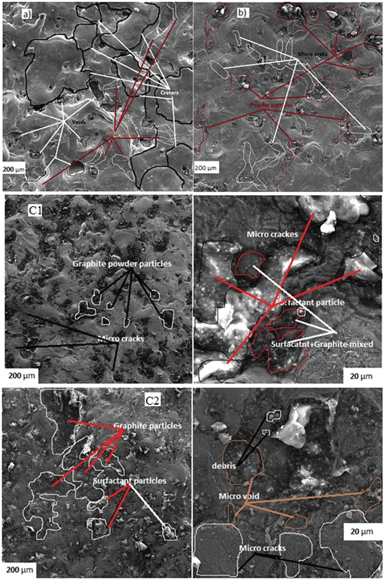
SEM images of the machined sample (a) without mixing graphite and surfactant, (b) with mixing graphite, and (c) with mixing graphite and surfactant concentration of (c1) 5 and (c2) 10 g/L.
The SEM micrographs of the workpiece surface machined with graphite powder and surfactant (6 g/L and 10 g/L) added in the dielectric fluid can be seen in Figure 11(c). It can also be clearly observed in Figure 11(c1) and (c2) that there are even craters, less micro-cracks (3–6 µm), less voids and more mixed particles like surfactant and graphite, and also agglomerated particles when the surfactant concentration is 10 g/L in the dielectric fluid (especially in Figure 11(c2)).
When the discharge current is applied to the machining zone, discharge energy strike the metal surface with more intensity, and a large quantity of molten and flushed metals are suspended in the electrical discharge gap during EDM. This results in the deterioration of the SR of the metal surface and causes poor surface finish, wider and deeper craters and cracks, due to high discharge energy transferred which acts with higher impulsive forces and stresses. 33 Another possible explanation for the formation of micro-cracks on the metal surface is the high discharge current (20 A) and pulse duration (65 µs) that can melt titanium alloy grains in later stages of discharge duration, thus contaminating the spark gap. It resulted in the deterioration of the mechanical properties and increase in cracks on the top layer. 34
EDX analysis
The EDX analysis of workpiece shows the presence of metal particles other than the base metal. The metal particles moving from electrode to workpiece are flushed out by continuous flow of dielectric fluid. Some amount of material is deposited on the machined surface of the workpiece because of the particles that cannot be moved completely or flushed out of the discharge gap. This implies that a significant amount of material is transferred from the electrode to the workpiece that is submerged in the dielectric fluid. EDX results show improved quality and quantity of elemental composition on the titanium workpiece and copper electrode. Figure 12(a)–(c) shows the composition of surfaces machined by EDM using various surfactant concentrations of 5, 6 and 10 g/L, respectively.
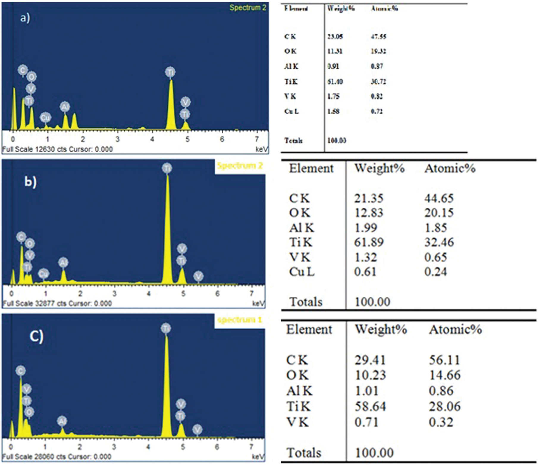
EDX analysis of the machined titanium alloy surface with surfactant concentrations of (a) 5, (b) 6, and (c) 10 g/L.
Figure 12(a) and (b) shows the machined sample using surfactant concentrations of 5 and 6 g/L, in which various elements like carbon, oxygen and copper are visible in the composition. Similarly, it can be seen from Figure 12(c) that the surfactant concentration of 10 g/L indicates the carbon and oxygen elements present on the machined surface by EDM. When surfactant concentrations of 5 and 6 g/L are added to the dielectric fluid, rapid oxidation of a discharge crater under high temperature takes place and shows the existence of oxygen gas. 13 In the discharge channel, very high temperature of around 10,000 °C–12,000 °C will be created, 31 and as a result, the surfactant added to the dielectric fluid decomposed and produced high oxygen and carbon. In such a case, the high oxidation and presence of small amount of copper and carbon elements contributed to higher rates of metal removal. It is clearly visible in the EDX result that medium amount of carbon, high amount of oxygen and low amount of copper are present on the machined surface. Under surfactant effect, more temperature is distributed on the machined surface and carbon debris is ejected from the workpiece material by melting and evaporation. Some of the sediments and graphite particles may be re-deposited on the surface of the workpiece and the carbon content on the surface improved.
When 10 g/L surfactant and 14 g/L graphite powder are added in a dielectric, more carbon particles would be resolidified as surface, and the amount of migration metal would also be higher and this is conformed with experimental results as shown in Figure 12(c). The amount of copper observed on the machined surface is about 1.58%, and oxygen is found to be about 12.83% higher with 5 and 6 g/L concentration of surfactant compared to that of 10 g/L surfactant concentration. This indicates that high amount of metal is removed from the electrode and migrated towards the workpiece surface.
Optimization using Taguchi’s technique
Determining the selection of performance parameters
Trials were conducted by changing one of the process parameters and keeping the other parameters constant. The working range of discharge current, surfactant concentration and powder concentration were explored by examining the MRR and RLT produced in the workpiece by the electrode. The working range of the process parameters selected under this study is presented in Table 5.
Selecting the L9 orthogonal array
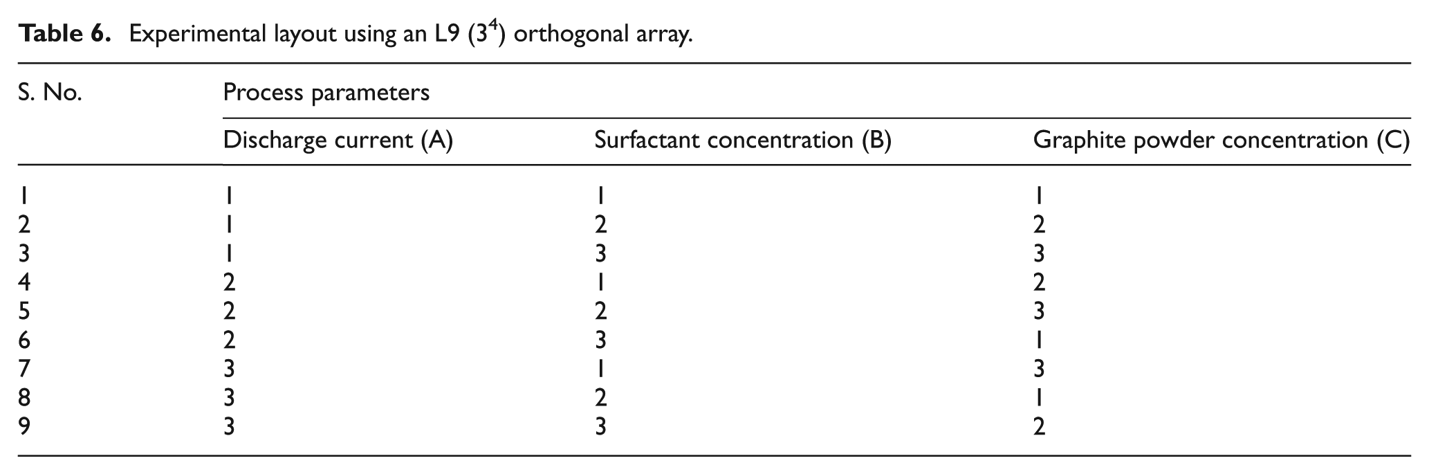
The number of process parameters considered was 3, and the level of each parameter was 3. The degree of freedom (DOF) of all three parameters was 2 (i.e. number of levels = 1) and the total DOF of all the factors was 6 (i.e. 3 × 2 = 6). The selected orthogonal array (OA) DOF (i.e. number of experiments − 1 = 9−1 = 8) must be greater than the total DOF of all the factors (6). Hence, L9 (3 4 ) OA is considered for this study. Based on the preliminary experimentation, there was no interaction between the selected process parameters. Hence, an interaction was not considered for this study. Three trials of each experiment were conducted, and the average of these three values was presented to minimize the pure experimental error. The selected OA is presented in Table 6.
Experimental layout using an L9 (3 4 ) orthogonal array.
Identify the optimum output performance condition and its effect on parameters
The Taguchi technique is very efficient to deal with responses affected by many parameters. It is an easy, effective and efficient approach to determine optimal process parameters. It is a powerful design of experimental tool which reduces drastically the number of experiments that are required to model and optimize the responses. It also saves a lot of time and experimental cost. The Taguchi method is devised for optimization and identification of optimum levels of process parameters for given responses.35–37 In the Taguchi method, the experimental values of various responses are further transformed from signal-to-noise (S/N) ratio. The response that is to be maximized is called ‘higher the better’ and the response that is to be minimized is called ‘lower the better’. Taguchi used the S/N ratio to measure the deviation of the response from the mean value. S/N ratios for ‘higher the better’ and ‘lower the better’ characteristics are calculated using equations (1) and (2), respectively
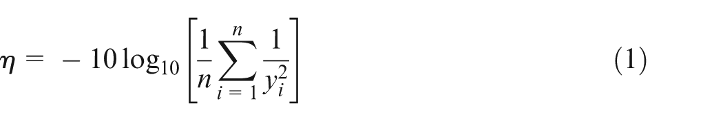
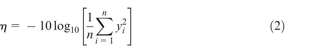
where η denotes the S/N ratio of experimental values, yi represents the experimental value of the ith experiment and n is the total number of experiments. By using the above equations, the S/N ratio values of machining performance for each experiment of L9 OA can be calculated for the MRR, SR and RLT values and are presented in Table 7. By using the experimental results and worked out values of the S/N ratios, the average effect response value and the average S/N response ratios are calculated for MRR, SR and RLT and are presented in Table 8. The S/N ratio response graphs for MRR, SR and RLT are shown in Figures 4–6, respectively. A higher S/N ratio value corresponds to a better performance. Hence, the parameters with the highest S/N ratio values will be the optimum level parameters.
Average results of MRR, SR and RLT.

MRR: material removal rate; SR: surface roughness; RLT: recast layer thickness.
Average results of MRR, SR and RLT and their corresponding S/N ratios.
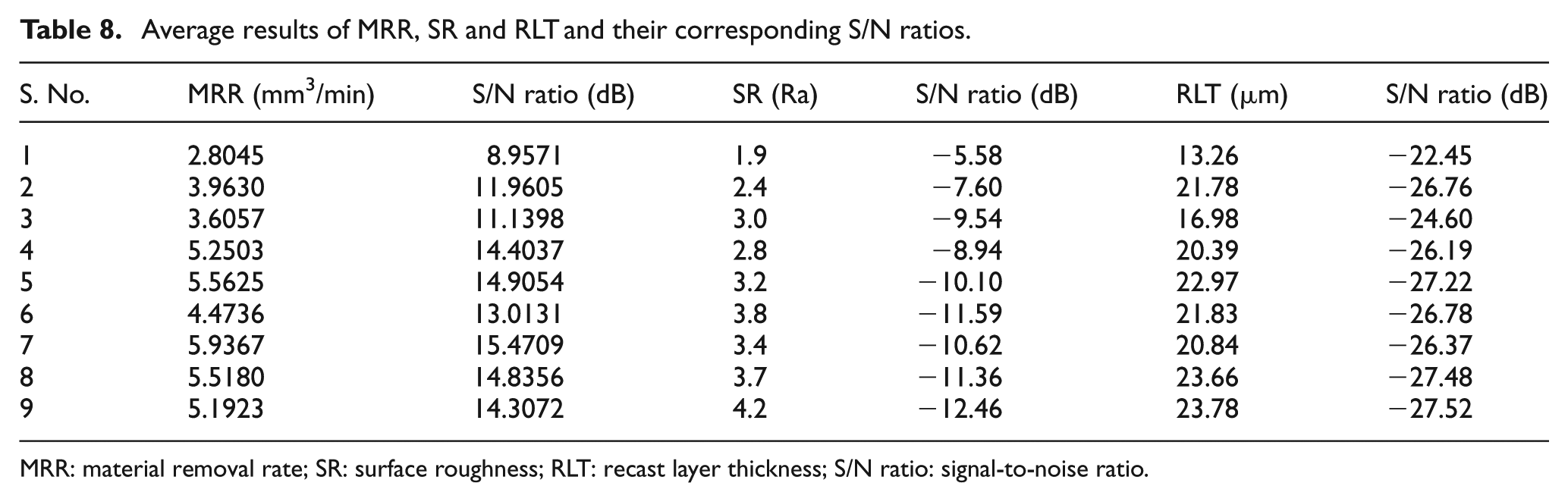
MRR: material removal rate; SR: surface roughness; RLT: recast layer thickness; S/N ratio: signal-to-noise ratio.
Analysis of variance
The analyses of variance (ANOVAs) are influenced by the process parameters on various performance measures. F-test values are used to determine the importance of various process parameters. The ANOVAs are shown in Tables 9–11.
ANOVA for MRR.

ANOVA: analysis of variance; MRR: material removal rate; SS: sum of squares; MS: mean square; DOF: degree of freedom.
ANOVA for SR.
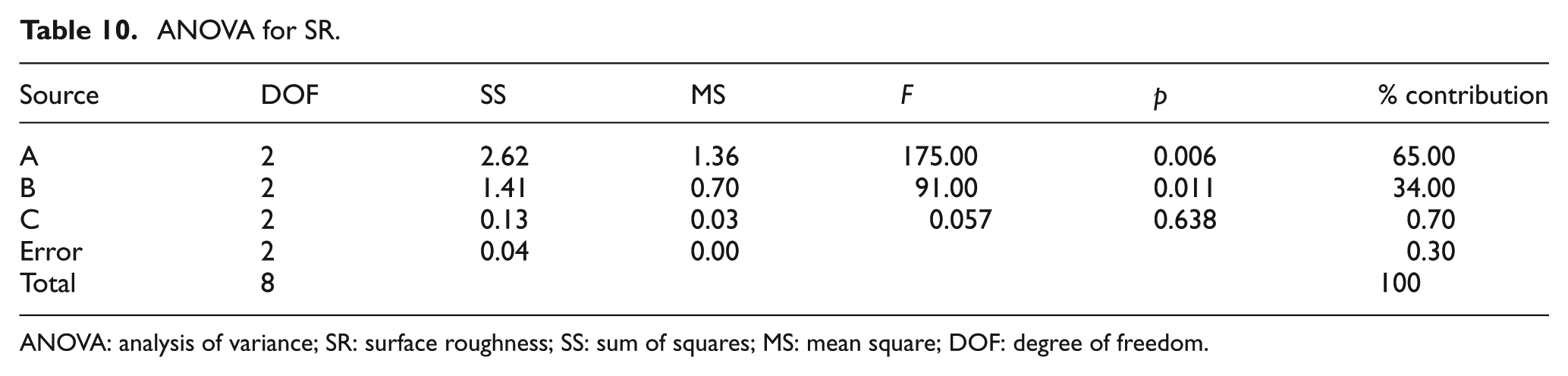
ANOVA: analysis of variance; SR: surface roughness; SS: sum of squares; MS: mean square; DOF: degree of freedom.
ANOVA for RLT.
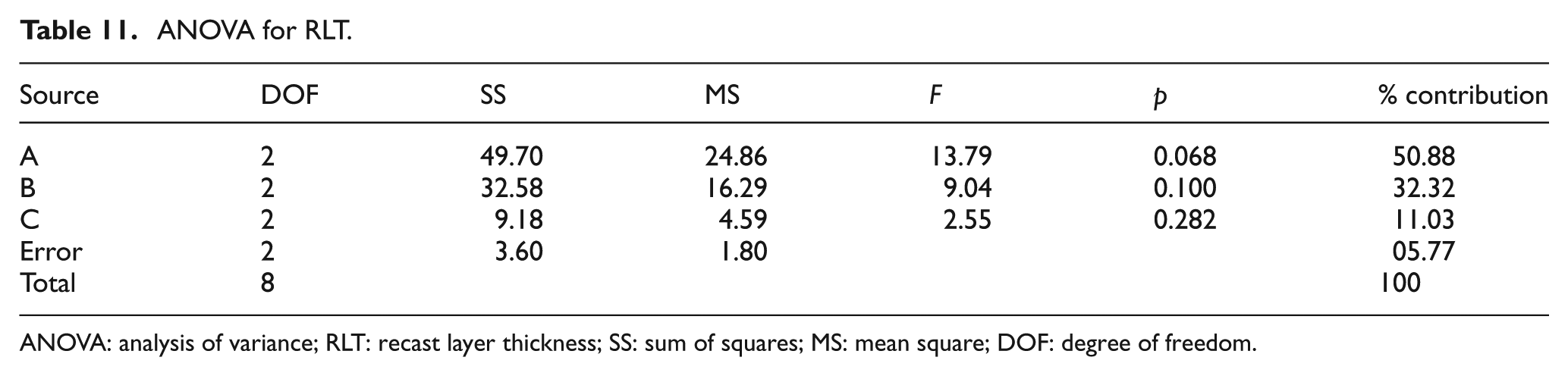
ANOVA: analysis of variance; RLT: recast layer thickness; SS: sum of squares; MS: mean square; DOF: degree of freedom.
ANOVA of MRR
Table 9 shows the OA-based experimental results of the MRR and its corresponding S/N ratio, whose ANOVA results are listed in Table 9. The ANOVA results and F-test values indicate that the most significant factor is discharge current (81.83%) compared to other factors like surfactant concentration (5.97%) and graphite concentration (10.53%). The S/N ratio response graph in Figure 13 shows that the MRR increases upon increasing the discharge current. In other words, higher discharge current is the key factor to obtain the higher MRR in EDM of the titanium alloy.
S/N graph for material removal rate.
Figure 13 shows that the A3B2C3 parameters, that is, the discharge current of 20 A, surfactant concentration of 6 g/L and graphite powder concentration of 13.5 g/L, respectively, are the optimal conditions for better MRR.
ANOVA of SR
Table 9 shows the OA-based experimental results of SR and its corresponding S/N ratio, whose ANOVA results are listed in Table 10. The ANOVA results and F-test values show that the most important parameters are discharge current (65.00%) and surfactant concentration (34.00%). The S/N response graph in Figure 14 shows that the SR decreases upon decreasing the discharge current. In other words, the graphite powder concentration (0.70%) is the less significant factor to obtain the lower surface finish in EDM of the titanium alloy.
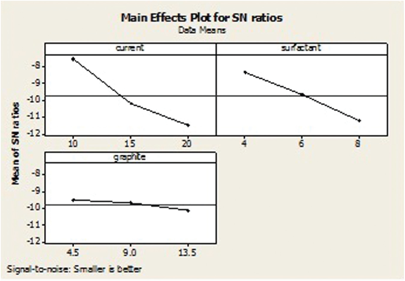
S/N graph for surface roughness.
Figure 14 shows that the A1B1C1 parameters, that is, the discharge current of 10 A, surfactant concentration of 4 g/L and graphite powder concentration of 4.5 g/L, respectively, are the optimal conditions for improved SR.
ANOVA of RLT
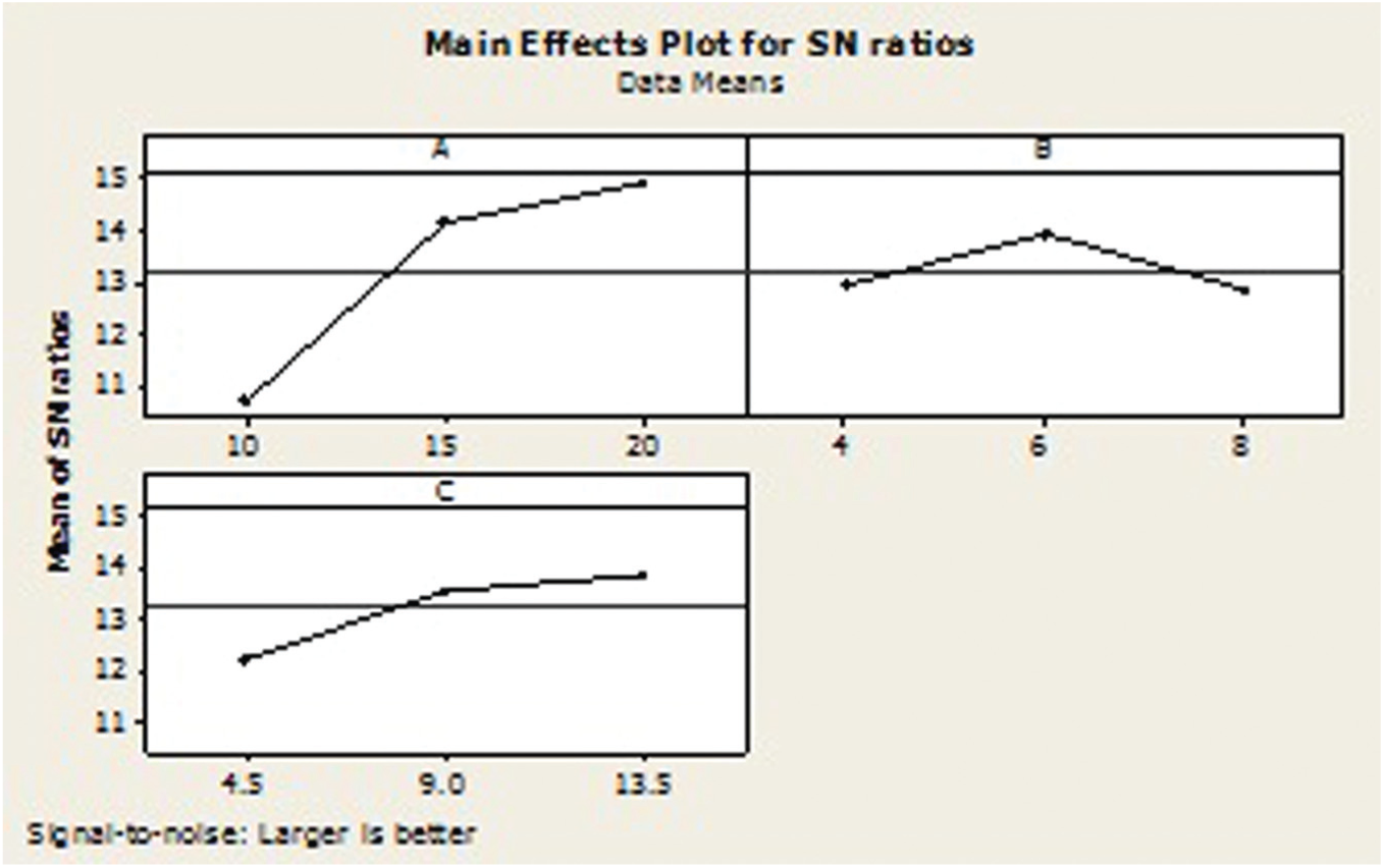
Table 9 shows the OA-based experimental results of RLT and its corresponding S/N ratio, whose ANOVA results are listed in Table 11. The ANOVA results and F-test values indicate that the most significant factors are discharge current (50.88%) and surfactant concentration (32.32%). The S/N response graph in Figure 15 shows that the RLT decreases upon decreasing the discharge current and surfactant concentration. In other words, the graphite powder concentration (11.03 %) is the less significant factor to obtain the lower RLT in EDM of the titanium alloy.
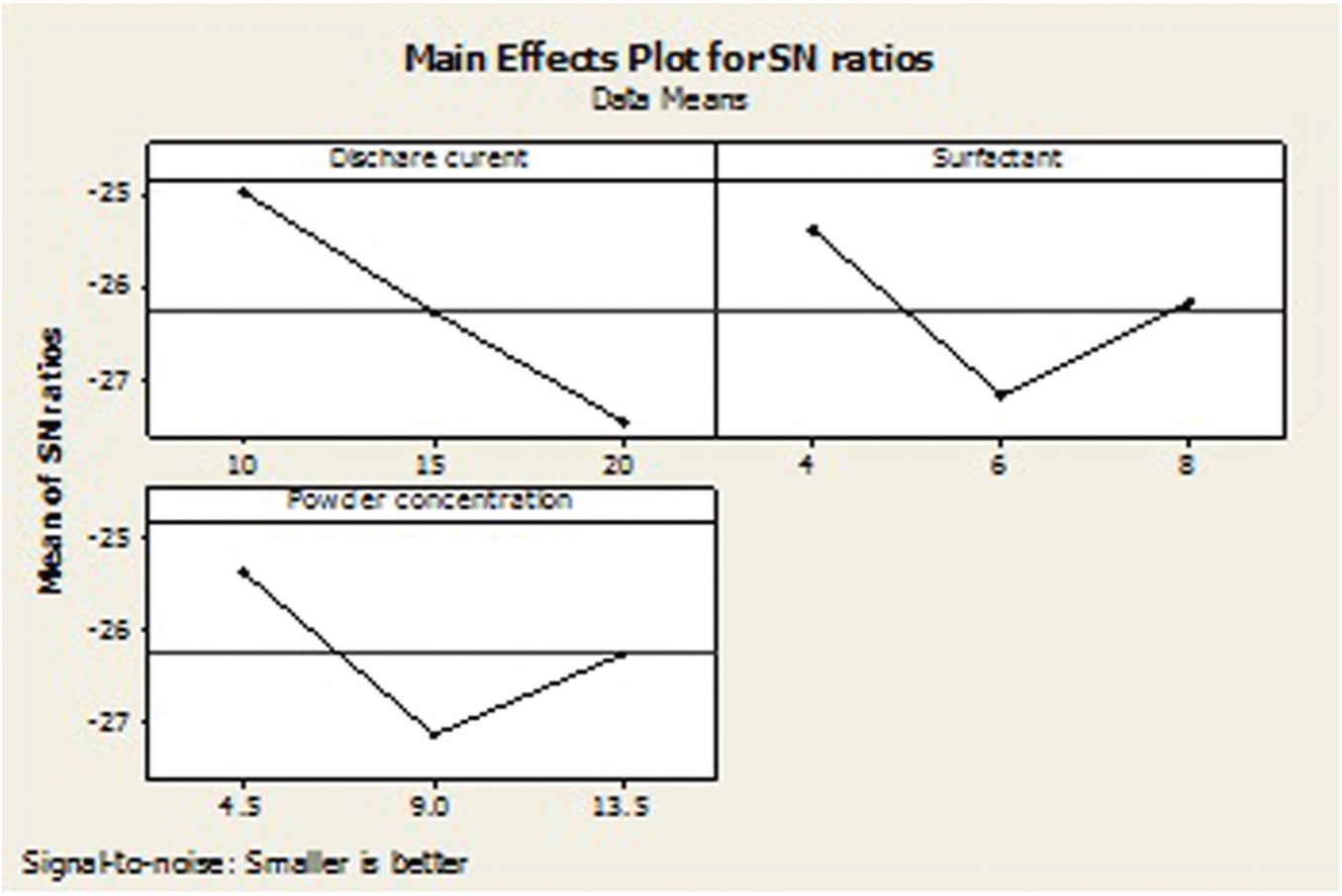
S/N graph for recast layer thickness.
Figure 15 shows the that A1B1C1 parameters, that is, the discharge current of 10 A, surfactant concentration of 4 g/L and graphite powder concentration of 4.5 g/L, respectively, are the optimal conditions for improved RLT.
Confirmation test
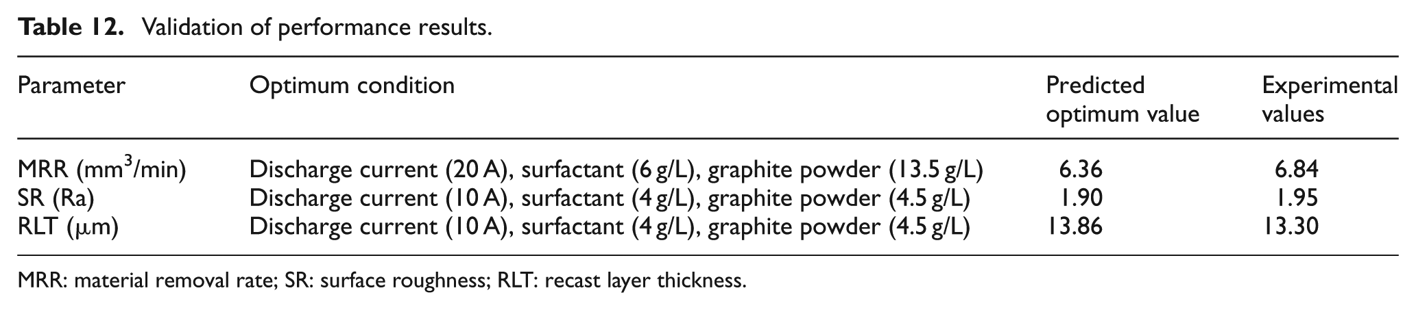
As the optimum condition of the EDM process parameter set is obtained, the confirmation conditions are processed to check the performance parameters’ improvement. The results of confirmation test are compared with the outcome of the OA experimental values and prediction of the design operating parameter values. Table 12 shows the comparison of the experimental results using the initial (OA) and final (predict design) EDM process parameters on the titanium alloy.
Validation of performance results.
MRR: material removal rate; SR: surface roughness; RLT: recast layer thickness.
Conclusion
An experimental study has been conducted to investigate the effect of surfactant added to the dielectric fluid (14 g/L + EDM oil) on MRR, SR, RLT, dielectric fluid behaviour, surface morphology and EDX analysis in EDM of the titanium alloy:
Surfactant added to the dielectric fluid significantly reduces the agglomeration of graphite particles and sediment particles.
The MRR increases for the surfactant concentration of 6 g/L added into the dielectric fluid.
SR reduces by adding surfactant in the dielectric fluid; the lowest SR was achieved at a surfactant concentration of 0.25 g/L.
RLT is reduced by mixing surfactant to the dielectric fluid. The surfactant concentration in the range of 1–6 g/L when added to the dielectric fluid results in the formation of undulated type of recast layer, and by mixing the surfactant at a concentration of 10.0 g/L to the dielectric fluid, even recast layers are formed on the machined surface.
The less micro-cracks and even craters on the workpiece surface machined by EDM are formed with surfactant concentration of 6.0 g/L added to the dielectric fluid.
The EDX analysis results show that the amounts of copper, carbon and oxygen elements are migrated between the tool and the workpiece surface.
The ANOVA and F-test of experimental data values related to the important process parameters of EDM revealed that the discharge current (A) and graphite powder concentration (C) influenced the MRR. The discharge current (A) and surfactant concentration (B) are affected by the SR and RLT.
The MRR at the optimum condition (i.e. A3B2C3) is increased with an increase in the discharge current and graphite powder concentration. As the surfactant concentration increases, it increases the MRR initially; the surfactant concentration of 6 g/L decreases the MRR.
The optimum condition for SR was observed at A1B1C1 having lower values of discharge current, surfactant and graphite concentration. It was observed that the SR is directly proportional to the discharge current, surfactant and powder concentration.
The optimum condition for RLT was observed at A1B1C1 having lower values of discharge current, surfactant and graphite concentration. It was observed that the RLT is directly proportional to the discharge current and powder concentration. As the surfactant concentration increases, the RLT increases initially (4–6 g/L) and then decreases (6–8 g/L).
Footnotes
Acknowledgements
The authors would like to thank the authority of Mishra Dhatu Nigam Ltd Hyderabad, India, for providing the material.
Declaration of conflicting interests
The authors declare that there is no conflict of interest.
Funding
This research received no specific grant from any funding agency in the public, commercial, or not-for-profit sectors.