
Abstract
Detection of tool–workpiece contact before the start of precision machining application is essential as it prevents tool breakage and aids in maintaining the accuracy of the machined workpiece. In this research, a wireless-aided three-axis accelerometer attached to a rotating micro-milling tool is used to detect tool–workpiece contact before the start of micro-milling operations. A three-axis accelerometer (ADXL345), an X-Bee pro wireless module and ATMEL328PP-U microcontroller along with other ancillaries were housed on a printed circuit board rigidly attached to a micro-milling tool using couplings. Subsequently, the micro-milling operation was conducted on three different materials, namely, aluminum, copper and brass, for three different revolutions per minute, depth of cut and feed velocity combinations. The accelerometer signals were received wirelessly in a personal computer. Impulsive change in accelerometer signal along Z-axis during machining indicated tool–workpiece contact. The depth of cut of the machined samples was measured using a profilometer. It was found that the setup was accurate in determining tool–workpiece contact at the start of micro-milling operations.
Introduction
Precision machining processes like micro-milling, micro-turning and micro-drilling have gained significant popularity in today’s world of miniaturization due to their ability to generate ultra-precise holes to complex three-dimensional (3D) features. In all the aforementioned processes, there is a continuous contact between the tool and the workpiece to be machined. The accuracy and repeatability of these processes hence depend on a number of factors like positioning of tool and work before the start of operations, type of the material machined, machining parameters and microstructural material interactions.
Among all these factors, proper tool–workpiece positioning or tool–workpiece contact detection before the start of machine operations is important, as this factor acts as a reference for all other operations that are performed. Usually before the start of machining operations, a predefined revolutions per minute (RPM), feed velocity and depth of cut are logged into the computer numerical control (CNC) machine. The operator using his experience sets the contact between the tool and the workpiece. The predefined depth for machining acts from this contact point into the material. In conventional machining operations, the operator progresses the tool near to the workpiece and by pinching a piece of paper repeatedly between the tool and the workpiece tries to find out if the contact between the two has occurred. Once the operator finds that the paper no longer goes inside tool–workpiece contact point, it is assumed that the contact is achieved. This approach cannot be used for micro-scale material process as the thickness of the paper may be greater than 100 µm and hence inaccuracies would creep in machining.
Before the start of the operations, if tool–workpiece contact is not detected properly, consequences of tool breakage or inaccurate machining occur.1,2 The phenomenon can be understood by an example. Let us consider that the operator has assumed tool–workpiece contact when there was a gap of 10 µm between the tool and the workpiece (Figure 1(a)). In this case, if the depth of cut assigned was 100 µm, then the machined piece will show a depth of 90 µm. Thus, inaccurate machining occurs. On the contrary, as in Figure 1(b), if the operator assumes tool–workpiece contact when the tool goes inside the workpiece by 10 µm, instant tool breakage and surface damage occur.
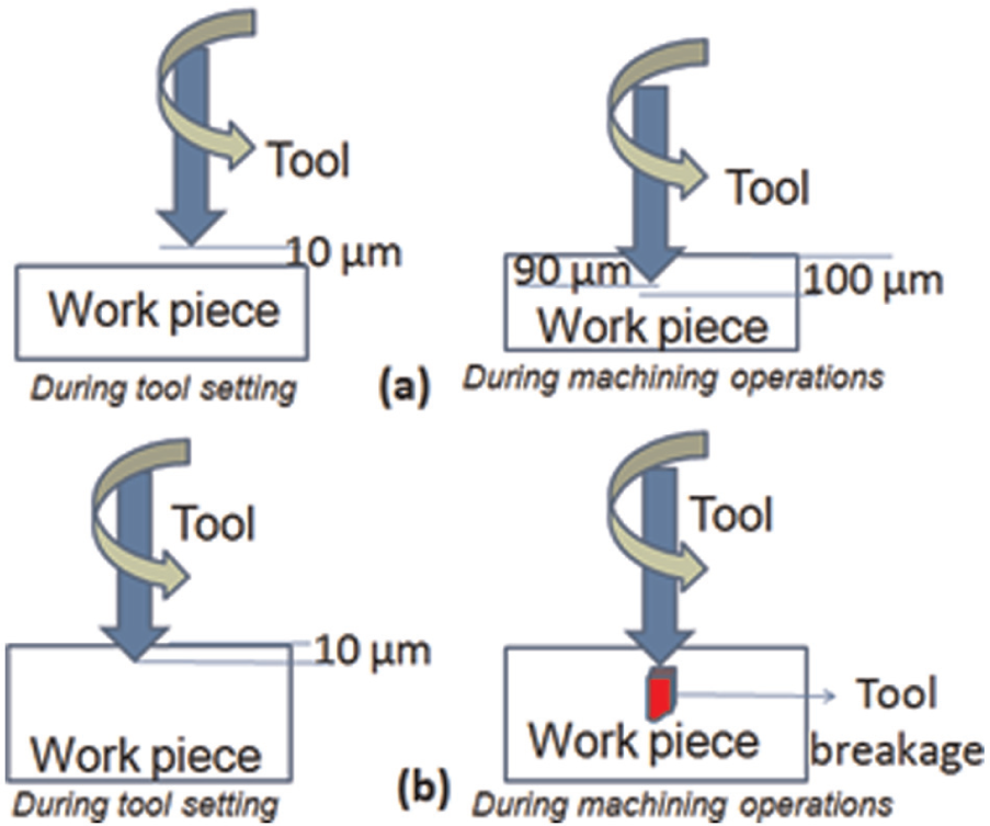
Erroneous tool setting condition: (a) when the tool does not touch the workpiece and its consequences during machining and (b) when the tool goes inside the workpiece and its consequences during machining.
The problem stated above gets intensified for micro-milling operations due to miniature tool size which is difficult to be visualized by human eye. Further in micro-milling, the tool tip is weak and the tool rotates at high speed. At times, it occurs that there is tool breakage due to improper tool–workpiece contact detection before the machining starts due to the cutting forces. 3 This is detrimental in terms of investment for micro-scale production industries. In case when there is no tool breakage, inaccuracies creep in the machined piece due to improper tool positioning. At micro-scale, it is nearly impossible to reassign the accuracy by machining the work for second time due to the limited size of the already machined inaccurate part. It is hence required to devise some methodology for accurate tool–workpiece contact detection in micro-milling process, so that the process fidelity can be achieved and tool breakage can be alleviated.
Existing literature
Few researchers have already investigated tool–workpiece contact detection problem for contact-based material removal processes. The methods include use of acoustic emission (AE) sensors, measurement of machining forces and their predictive assessment, use of laser tool setters and use of electrical continuity test.
In one of the reported literature, 4 variations in AE have been used in order to detect tool–workpiece contact. In this approach, the authors used an AE sensor attached to the bottom of the workpiece to capture the AE data. Though the system was reliable and could detect the contact accurately for smooth work surfaces, putting a sensor below the workpiece is not as sensitive as a sensor attached directly to the tool. Work surfaces may have significant microstructural defects, and the cutting tool experiences the effects for those defects at specific cutting point on the workpiece. 5
Use of machining force data 6 bears similar limitations as the dynamometer is attached to the bottom of the workpiece, and hence, accurate instant of impact occurring between the tool and workpiece is not taken care of.
Use of tool setters is a lucrative alternative to tackle the above-mentioned problem; however, thermal compensation for the rotating tool is to be taken into consideration. 7 During rotation, the tool gets heated up and there is an expansion in the tool tip. Furthermore, tool setters have to be set before start of every machining operation which is a tedious task for machine operators.
Electrical current continuity-based method 8 for tool–workpiece contact detection as suggested suffers from a limitation that the tool and the workpiece must be attached to some insulated surface to prevent inaccurate contact detection and leakage current flow.
It could thus be understood that the proposed methods in the literature bears some limitations. It was hence essential to suggest a method that is online and can directly monitor tool–workpiece contact with preserved re-configurability and 0 setup time. In this work, we propose a wireless-aided accelerometer sensor attached to the micro-milling tool using coupling and process the acceleration signals of three axes to detect tool–workpiece contact.
Proposed methodology
The method for tool–workpiece contact detection consists of a printed circuit board (PCB)–based platform that houses the entire circuitry and is attached to the rotating tool. The accelerometer data are logged into a PC where the signals are correlated to detect the instant of tool–workpiece contact. Details of the experimental setup and the data interpretation methods used are depicted in the following sections.
Experimental setup
The experimental setup consists of a PCB platform that houses an ATMEL 328 PP-U microcontroller, an X-Bee wireless module, accelerometer sensor ADXL345, batteries and other ancillaries. Due to the use of miniature electronic components, the diameter of the PCB-based platform could be limited to 8 cm and a net weight of 36 g. The PCB platform had a center hole through which the micro-milling tool passes. The tool used was supplied by Union Tools (Part No. HSLB2001-005). The tool is a ball end milling cutter with ball end radius of 50 µm and effective cutting length of 500 µm. The PCB was fitted to the tool using coupling on both sides. The coupling methodology and the assembly of the PCB platform with the tool using these couplings are shown in Figure 2. Such coupling methodology was used as it leads to a fit with 0 or nominal allowance. Thus, the coupling of the tool with the PCB platform becomes rigid which would allow the setup to be used at very high speeds required in micro-milling.
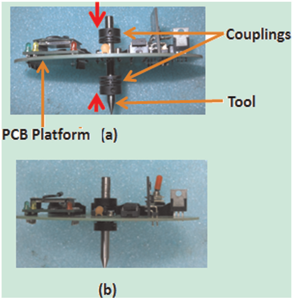
(a) Method to fix the PCB platform with the tool using couplings. (b) Tool–PCB platform assembly.
The tool along with the PCB platform was attached to Mikrotools DT-110 micro-machining center on which the experiments are carried out. The accelerometer sensor could sense a maximum acceleration of 2g units (where “g” is the gravitational acceleration). The experimental setup is as shown in Figure 3. For wireless transmission of accelerometer data, an X-Bee that uses IEEE 802.15.4 protocol was employed. Among various forms of wireless transmission, X-Bee was selected as it has low latency time (typically 15 ms for one-to-one communication), 9 thus satisfying real-time data transmission requirements of the setup.
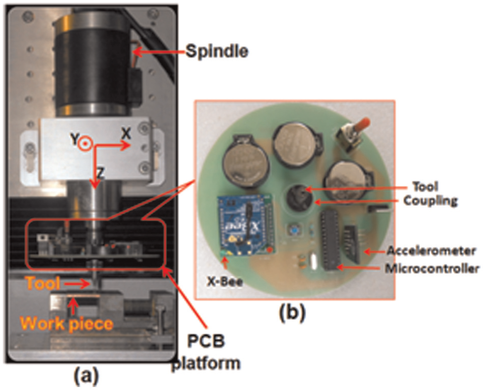
(a) Experimental setup for micro-milling with PCB platform attached to the tool. (b) The fabricated PCB platform housing the accelerometer, controller and wireless module.
Experiments conducted
Milling operation was conducted on three different materials, namely, Aluminum 6061, oxygen free highly conducting (OFHC) copper and brass. The machining conditions under which each of these materials was machined are presented in Table 1.
Machining parameters for the experiment.
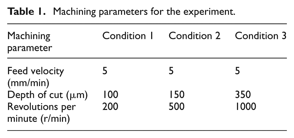
Acceleration data for X-, Y- and Z-axes were logged in the PC for nine different combinations of feed, RPM and depth of cut for each of these materials. These data were plotted for analysis. An impulsive change in Z-axis acceleration was taken as a measure for tool–workpiece contact detection. The impulsive change was detected by slope angle–based criterion. 10 An overview of the same is presented next.
The data points obtained from the accelerometer plots are in the form (ti, zi), where “t” (time) is in the X-axis and “z” (Z-axis acceleration) is in the Y-axis. “i” denotes the ith plot point.
The slope for a particular segment (j) of the plot is thus found by equation (1)

The change in slope of the consecutive line segments is given by equation (2)

The segment for which ΔSlope shows high variations than the previous ones is taken as the instant oftool–workpiece contact. The machining operations with predefined RPM, feed and depth of cut were started after the instant when tool–workpiece contact was detected.
The machined workpieces were then checked for the depth of cut using a stylus-type profilometer (PGI 400) manufactured by Taylor and Hobson. In such profilometers, a stylus traverses over the surface of the material whose profile analysis is to be carried out. The profile so obtained is called primary profile. 11 The primary profile (P-profile) for the cutting geometry was recorded and the depth of cut was compared with the predefined depth of cut set to CNC controller before start of machining operations.
In order to properly correlate the acceleration values during machining with the depth of cuts, microstructural surface evaluation was carried out under an optical microscope at 100 × magnification.
Results and discussions
The acceleration during machining aluminum, copper and brass for three different machining conditions as in Table 1 is stated in Figure 4.
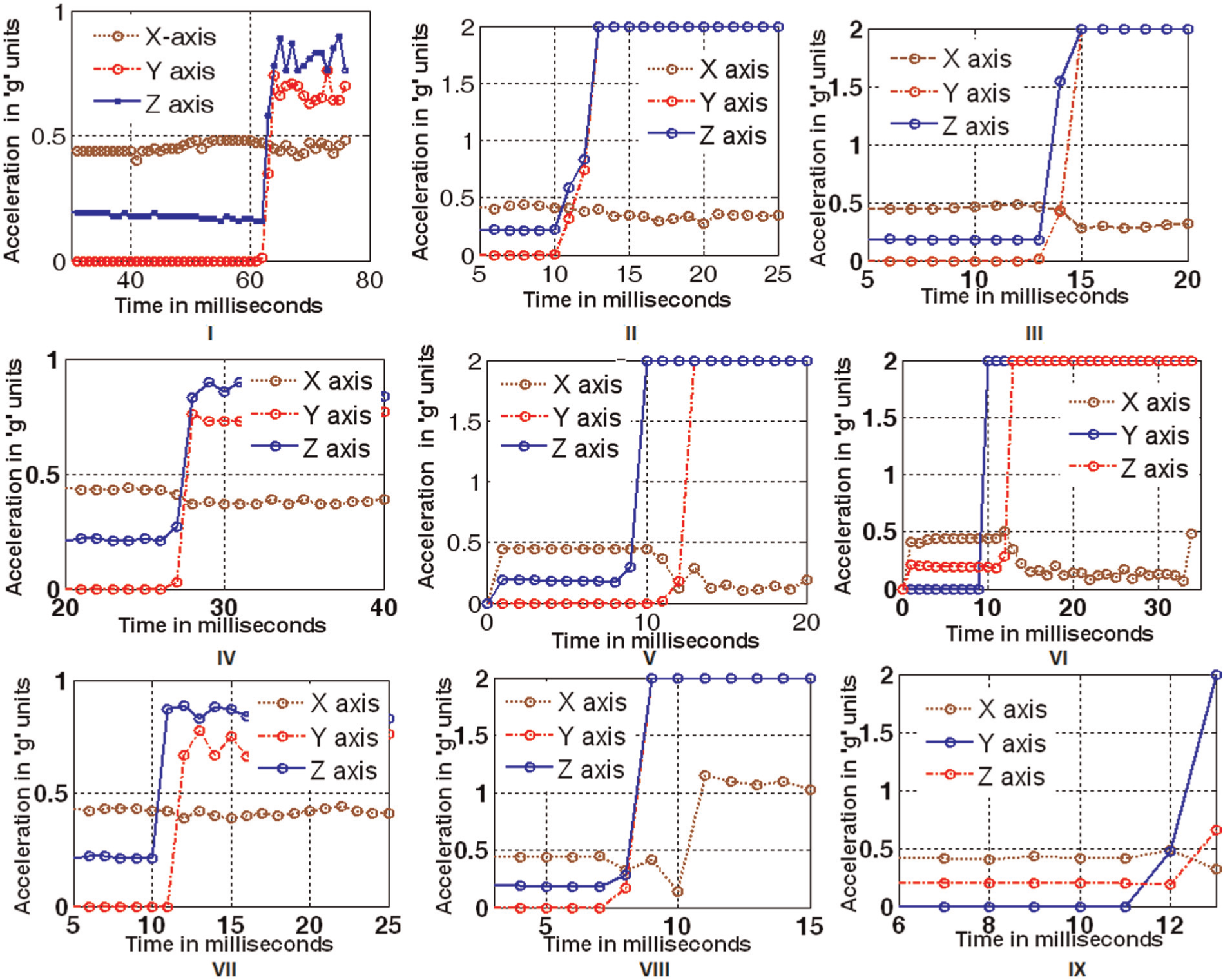
Acceleration profiles along X-, Y- and Z-axes for Aluminum (I with condition 1, II with condition 2 and III with condition 3), copper (IV with condition 1, V with condition 2, VI with condition 3) and brass (VII with condition 1, VIII with condition 2, IX with condition 3) with machining conditions in Table 1.
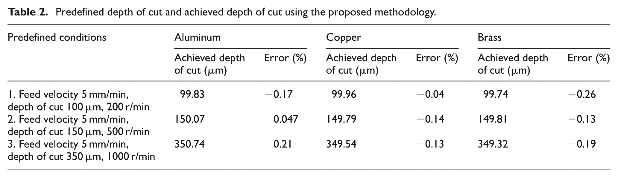
The tool–workpiece contact was determined at the point of time where the acceleration along Z-axis changes abruptly (i.e. rate of change of acceleration is maximum). The depths of the machined profiles were found using a stylus-type profilometer. The depth profile for one of the intended depth (350 µm) for aluminum is shown in Figure 5. The predetermined depth of cut and real depth of cut after machining operations for all the samples machined are presented in Table 2.
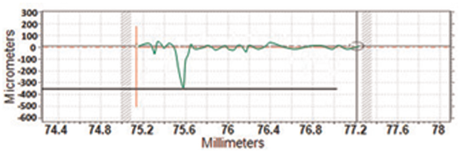
Primary profile for aluminum machined with set depth of cut of 350 µm.
Predefined depth of cut and achieved depth of cut using the proposed methodology.
The microstructural surface quality for the materials considered for machining is as shown in Figure 6.
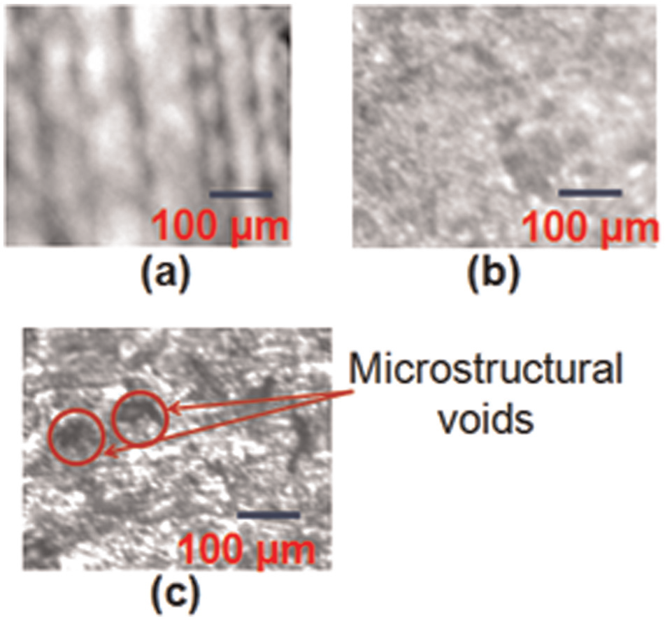
Microstructural surface quality for the work materials: (a) aluminum, (b) copper and (c) brass.
The following inferences could be drawn from the results obtained:
The acceleration value along the Z-axis changes abruptly on tool–workpiece contact and hence are a prominent measure for detection of tool–workpiece contact (Figure 4). Good accuracy could be found in tool–workpiece contact detection process using this technique (Table 2).
At low RPM, the abrupt change in acceleration along Z-axis is prominent (Figure 4 I, IV and VII); however, at higher RPM, a few sub transitions could be seen within the abrupt change duration. This could be accounted due to an increase in plasticity of the material while machining at higher speeds. 12 At higher speeds, the temperature induced at the tool tip is higher which leads to enhancement of plastic behavior of the materials machined.
Higher inaccuracy in tool–workpiece contact detection could be found while machining at higher RPM. This may be accounted due to higher thermal elongation of the tool tip while the tool rotates at higher RPM. 13
Fluctuation in Y-axis acceleration is higher in brass than aluminum and copper (Figure 4). This may be accounted due to higher amount of microstructural defects formed on brass surface during alloying (Figure 6). In aluminum, a few straight line–type projections on the surface could be found while brass had microstructures.
Conclusion
In this work, a simple, cost-effective, reconfigurable and real-time approach–based method is proposed for detection of tool–workpiece contact in micro-milling process. The highest inaccuracy in machining while using this methodology does not exceed 0.26%. Furthermore, the process could be used for the materials with higher microstructural surface defects.
The methodology adds to accuracy as the microelectromechanical system (MEMS)-based accelerometer is attached directly to the rotating tool rather than to some fixed part of the machine as found in previously proposed methods. The footprint and weight of the system are reasonable which allow easy integration with standard industrial micro-milling machines. The methodology would thus be beneficial for production industries as tool breakage due to improper tool–workpiece detection could be mitigated and proper depth of machined workpiece could be achieved.
Footnotes
Declaration of Conflicting Interests
The author(s) declared no potential conflicts of interest with respect to the research, authorship, and/or publication of this article.
Funding
The author(s) disclosed receipt of the following financial support for the research, authorship, and/or publication of this article: This work was funded by CSIR-12th FYP, Govt. of India (grant no. ESC0112-RP-II-T2.2).