
Abstract
This article discusses the effects of process parameters (feed and spindle speed) on quality characteristics (thrust force, torque, surface roughness and ovality) for standard and special geometric design of a drill body in dry drilling of pultruded and sheet moulding compound thick composites. Pultruded (non-laminated) and sheet moulding compound (laminated) thick glass fibre–reinforced plastic composites with a higher percentage of fibre weight fraction are extensively used in construction of bridges, prefabricated platforms, ballistic applications, structural applications, instrument bases and automotive load floors, and therefore, prediction of better performance drill helps the fabrication industry in making good quality holes. The drilling experiments using coated tungsten carbide drills, twist drill (standard geometry) and ratio drill (special geometry) of diameter of 10 mm were conducted using response surface methodology. Analysis of variance of the experimental results reveals that for both twist drill and ratio drill, feed is more significant in influencing the quality characteristics. The experimental values obtained for quality characteristics are empirically related to process parameters by developing response surface models using Design-Expert software. Analysis of the experimental results reveals that ratio drill performs better in pultruded composites and twist drill performs better in sheet moulding compound composites. The optimal process parameter levels within the selected range for minimizing all the quality characteristics together were determined.
Keywords
Introduction
Glass fibre–reinforced plastic (GFRP) composites are most widely used in aerospace, automotive, marine, process industries, construction of military vehicles and machine tools due to their multi-potential properties such as high strength-to-weight ratio, high fracture toughness and good dimensional stability.1,2 Accordingly, the need for accurate machining of composites has increased enormously. Intricacy in the product design necessitates development of the composite product in parts, which are finally assembled. Hole making thus becomes an essential part in product development.
The workpiece is subjected to delamination, fibre breakage, matrix cracking and so on while drilling fibre–reinforced composite materials.3,4 Among these defects caused by drilling, delamination which occurs both at the entrance and exit planes of the workpiece is most critical, since it can result in lowering of bearing strength and thereby reduces service life of the component.3,5,6 Bearing strength is also affected by surface roughness of the side walls of the drilled hole. Hence, utmost care is to be exercised to attain defect controlled drilling performance. The fastening efficiency is largely dependent on the bearing strength which defines the quality of machined holes. Many researchers have proposed that the quality of machined holes is strongly dependent on process parameters such as feed and spindle speed2,3,7–10 which have great influence on the thrust force and torque.
Many attempts have been made by various researchers in drilling thin laminated glass fibre–reinforced composites. They are briefly presented here. Caprino and Tagliaferri 4 found that feed rate significantly influences the damage induced in glass/polyester composites while drilling. König and Grass 11 stated that cutting forces such as thrust force and torque, which depend on cutting parameters, affect the surface quality. Chen 12 correlated the delamination factor with the average thrust force for the drilling of unidirectional (UD) and multidirectional composite materials. Takeyama and Lijima 13 studied the surface roughness on ultrasonic machining of GFRP composites. According to them, higher cutting speed produces more damages on the machined surface. This is because of higher cutting temperature, which results in local softening of work material. When GFRP composites are machined, it is clearly seen that the fibres cut across and along their lay direction, leaving deformed projections and partially disclosed fibres on the machined surface. 14 Ogawa et al. 15 stated that the mean value (static component) of the thrust force influences on a cutting phenomenon occurring at the chisel edge of the drill and the magnitude of variation (dynamic component) of the thrust force influences on a cutting phenomenon occurring at the major cutting edge of the drill. Singh and Bhatnagar 16 drilled UD glass fibre–reinforced polymer (UD-GFRP) laminates with different drill geometries and concluded that drilling-induced damage is not only dependent on thrust force alone but also on torque. They also found that the damage is maximum at higher cutting speeds and minimization of thrust force and torque during drilling can lead to minimal damage of the hole. Singh et al. 17 stated the need for a controller which can control thrust force, torque, cutting speed and feed rate to have damage free drilling in polymer matrix composites. Palanikumar 18 found that the grey relational analysis technique is more convenient for optimizing the drilling parameters within the levels studied. Khashaba et al. 19 studied the effects of feed, drill diameter and cutting speed on thrust force, delamination size and surface roughness while drilling GFRP composites. They found that the increase in the feed results in higher thrust force which in turn increases the resulting surface roughness and delamination damage and subsequently low bearing strength. Rajamurugan et al. 20 stated that feed rate is the factor which has great influence on the thrust force followed by the drill diameter in machining GFRP composites.
Mishra et al. 21 developed a predictive tool using artificial neural network for calculating the likely damage before actual drilling commences in UD-GFRP composite laminates. Rahamathullah and Shunmugam 22 suggested peck drilling for through-holes in microdrilling of GFRP specimens. Kishore et al. 23 exhibited a strong relationship between the drill point geometry and the drilling-induced damage while drilling fibre–reinforced plastic (FRP) composites. Faraz and Biermann 24 witnessed the major contribution of main cutting edges of a drill in inducing hole entry and exit delamination. Guo et al. 25 developed a model to optimize the cutting parameters and tool geometries for drilling carbon FRP composites using a twist drill. Nagarajan et al. 26 compared conventional and adjusted delamination factors and proposed a refined delamination factor based on digital image analysis.
The literature review shows that many researchers have worked towards attaining hole quality considering thrust force, torque, surface roughness and damage/delamination around the drilled hole in thin laminated composites. However, the literature on the drilling of laminated and non-laminated thick composites and that on the drilling of composites with special geometry is scarce. Non-laminated composites, because of its superior mechanical properties than laminated composites, find application in ballistic applications. In ballistic applications, mostly thick non-laminated composites with a higher percentage of fibre weight fractions are used to ensure higher order energy absorption. Hence, the research interest in the present study is to investigate the relative influence of drilling process parameters (feed and spindle speed) on quality characteristics (thrust force, torque, surface roughness and ovality) for standard and special geometry design of a drill body in both laminated and non-laminated thick GFRP composites. If quality characteristics can be improved, the bearing strength of the drilled holes and thereby the service life of the assembled components can be substantially increased. This investigation will be useful for the fabrication industry in predicting better performance drill while drilling pultruded (non-laminated) and sheet moulding compound (SMC) laminated composites. Pultruded composites find application in structural process equipment supports; flooring supports; prefabricated walkways, platforms and bridges; bumpers; bus components; cable-trays; chemical plant hand railings; gratings; ladders; fishing rods; electrical insulator rods and many other innovative new products. SMC composites find application in building products, automotive load floors, water tanks, structural applications, public transport seats, stadium seats, complex ribbed parts such as, automobile front-end panels, business-machine housing, instrument bases and many other innovative new products.
Experimental details
Pultruded (non-laminated) and SMC (laminated) composites with maximum fibre weight fraction were taken as workpieces. Pultruded composites were made using epoxy resin and electrically insulated and corrosive resistant (E-CR) glass directional roving fibres with 80% fibre weight fraction. SMC composite was made by compression moulding using epoxy resin and E-CR glass two directional woven rovings with 70% fibre weight fraction. The fibre weight fraction obtained is maximum with respect to the method of manufacturing. Pultruded and SMC bars having 90° fibre orientations with respect to the drill are 170, 55 and 20 mm in length, width and thickness, respectively. Pultruded composites having 0° fibre orientations with respect to the drill are 25 and 20 mm in diameter and thickness, respectively. Like sheet metal, composite materials having more than 6 mm thickness can be classified as thick composites. The mechanical properties of the workpieces have been found out by various tests and are presented in Table 1.
Mechanical properties of GFRP composites.
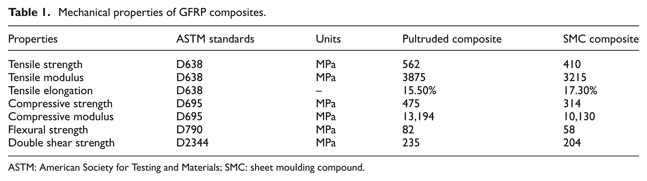
ASTM: American Society for Testing and Materials; SMC: sheet moulding compound.
The micrograph of pultruded and SMC composites obtained through a scanning electron microscope (SEM) is shown in Figure 1. The elemental composition of pultruded and SMC composite in weight % obtained through energy dispersive X-ray spectroscopy (EDX) with a spot size of 350 is given in Table 2. Twist drill (standard geometry, Sandvik No. R840 1000 A1A) and Ratio drill (special geometry, Guhring No. 02475), made of tungsten carbide of grade K, was used in this work (Figure 2) to produce through-holes. The name ratio drill arises due to cross shaped web thinning form which is similar to ratio cross. For the same coating, the difference in the colours of drills is due to the difference between drill companies in applying the same.
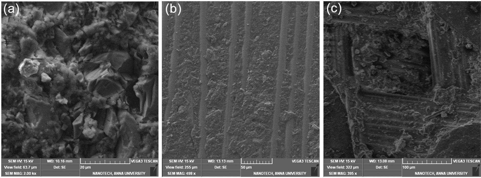
SEM image of workpieces: (a) pultruded rod, (b) pultruded bar and (c) SMC bar.
Elemental composition of the composites.
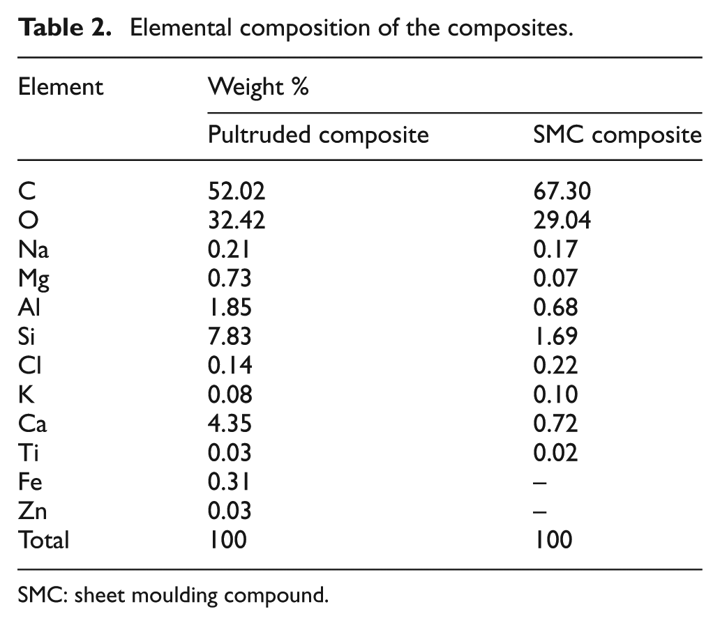
SMC: sheet moulding compound.
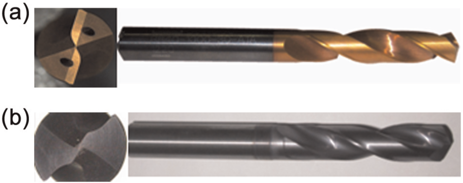
(a) Twist drill and (b) ratio drill.
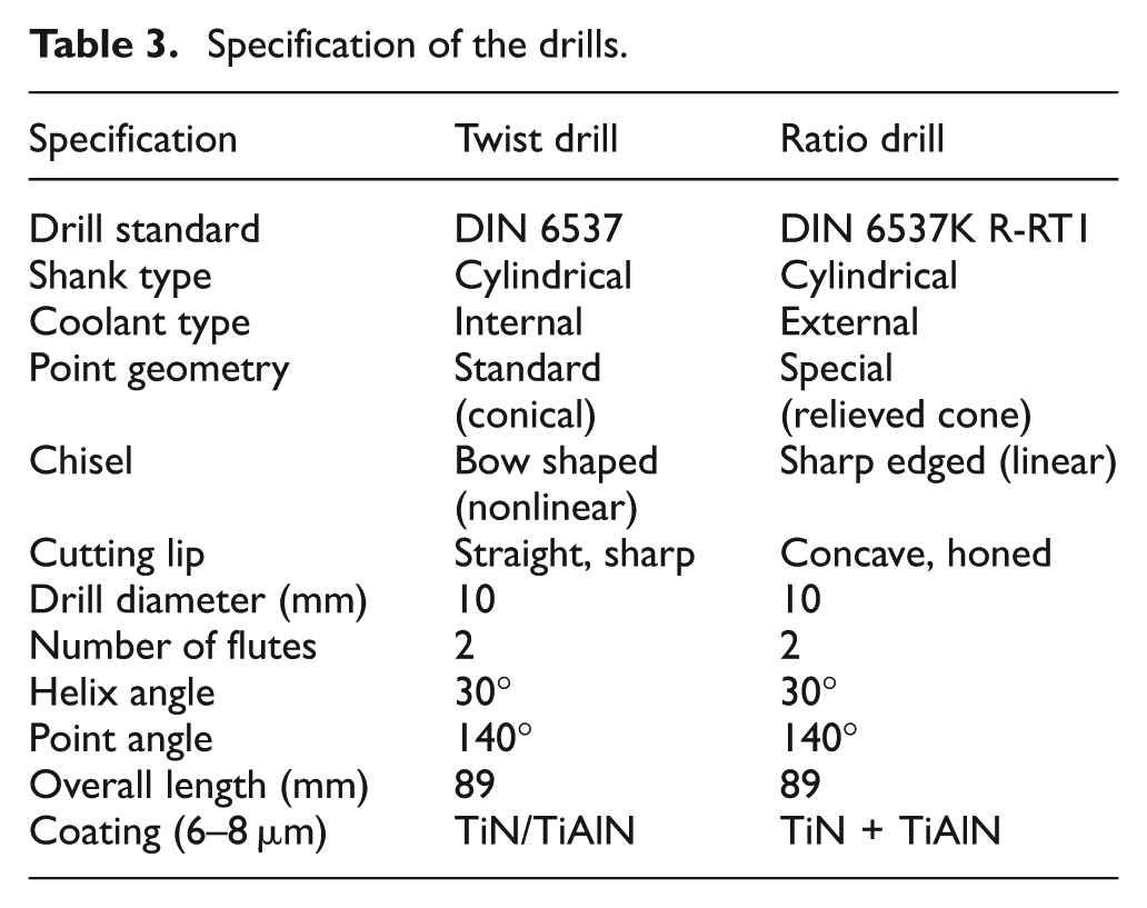
The specification of the drills is given in Table 3. Computer numerical control (CNC) machining centre (ARIX VMC 100) was used to perform the drilling operations. The workpiece was mounted on the fixture which in turn was mounted on a dynamometer on the table in CNC machining centre (Figure 3).
Specification of the drills.
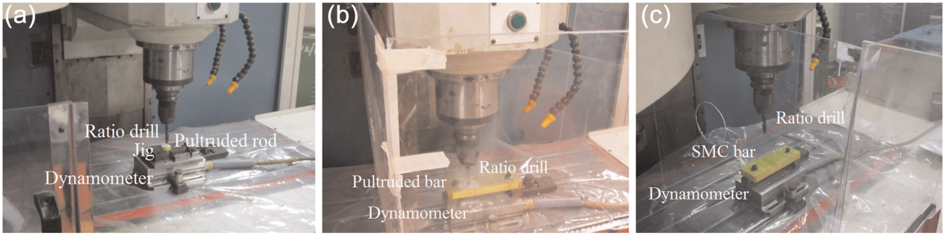
Experimental setup used in the study: (a) pultruded rod, (b) pultruded bar and (c) SMC bar.
Plan of experiments
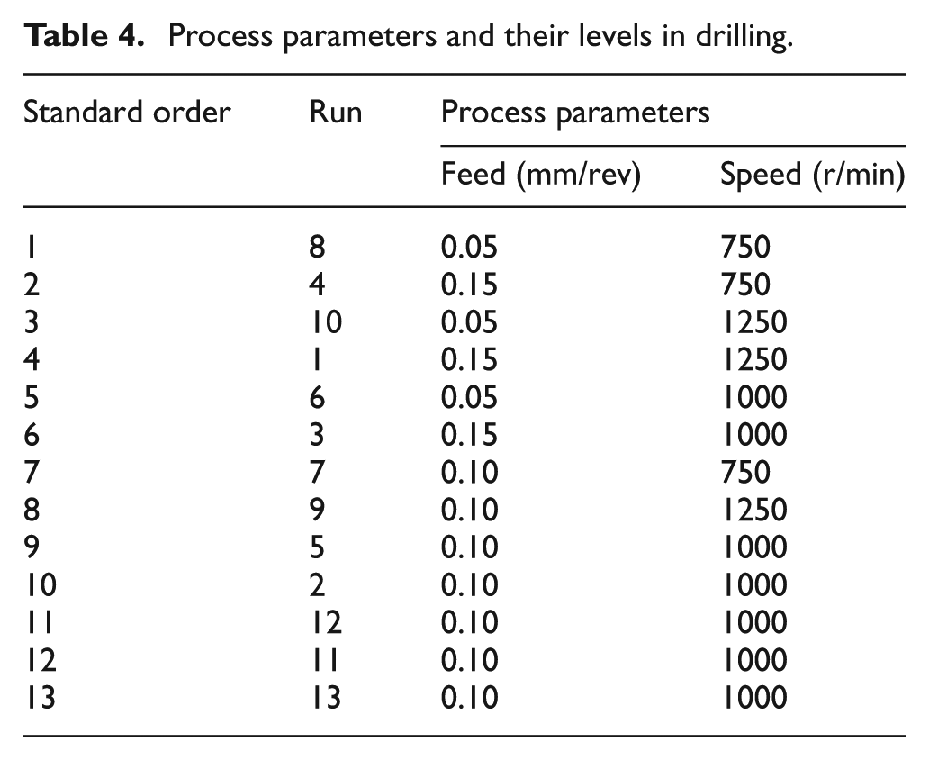
The response surface methodology (RSM) is a collection of mathematical and statistical procedures, used for the analysis of problems in which the desired response is affected by several parameters. 27 The experiments were designed by applying RSM with selected cutting conditions 16 using the Design-Expert (version 7) statistical software package. The process parameters and their levels selected for the experiments are presented in Table 4. In applying RSM, central composite face–centered (CCF) design with one block for one type of drill was used, which requires three levels of each parameter and yields 13 experiments (standard order) for two parameters. Each experiment has been repeated three times and average values of the dynamic component of thrust force, mean torque, surface roughness (Ra) and ovality were taken to study the relative significance of process parameters.
Process parameters and their levels in drilling.
Thrust force, torque, surface roughness and ovality measurement
The axial thrust force and torque during drilling were measured using a piezoelectric dynamometer (Kistler make, Model No. 9257B). Dynamic component of thrust force was taken into consideration for minimizing the damage of the hole. 15 The vacuum cleaner was used to remove powdery chips away from the cutting zone. The surface roughness of the side wall of the drilled holes was measured along the feed direction (i.e. across the lay) using a portable surface roughness measuring instrument, Surftest SJ-201P, whose stylus is of 6 mm height and 3.5 mm width and having a tip radius of 5 µm. The surface roughness instrument was set to a cut off length of 0.8 mm, traverse speed of 1 mm/s and an evaluation length of 4 mm. The ovality (imperfectness of circularity) of the drilled holes was measured using coordinate measuring machine (CMM), Tesa Micro-Hite 3D 474, which uses Tesa-Reflex MH3D software and TESASTAR probe head with adjustable trigger force. The surface roughness (Ra) and ovality were measured many times at the entry, middle and exit of the drilled holes and an average was taken for analysis. The average maximum flank wear of the drills was measured using two-dimensional vision measurement machine (Model OL-2515) having a resolution of 1 µm.
Experimental results and discussions
Pultruded composite with 0° fibre orientations
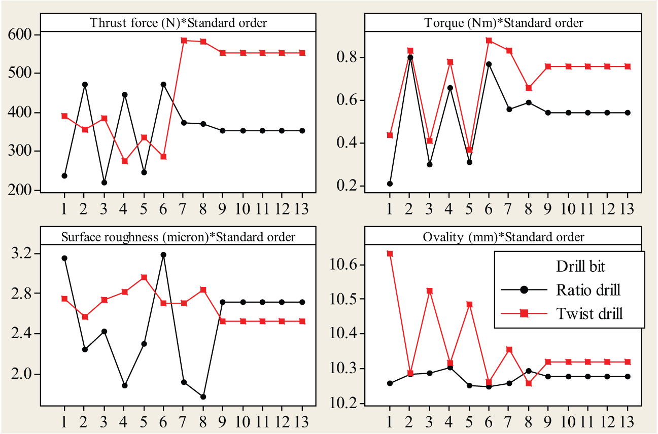
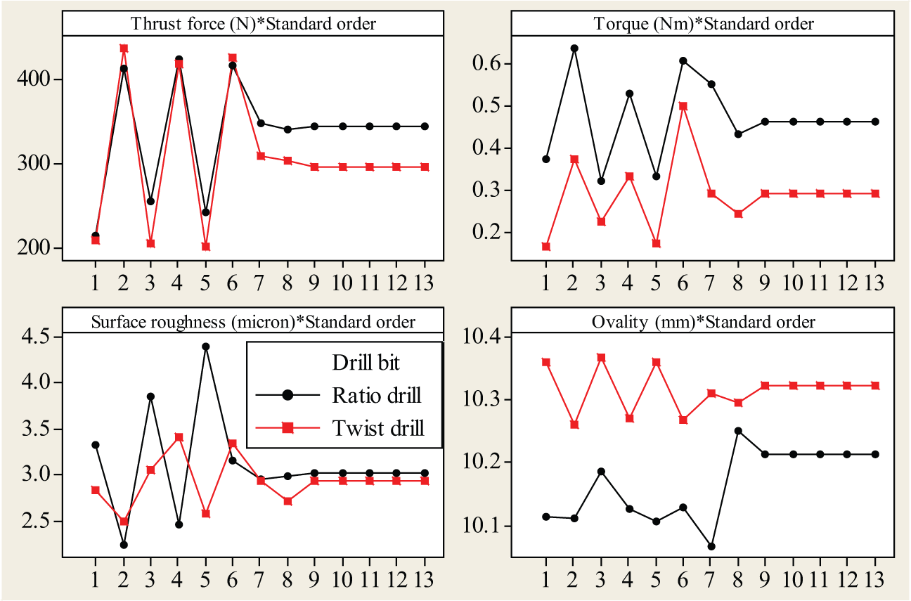
Two twist drills have been used for making 27 holes. The average flank wear of first twist drill after making 14 holes was 0.1133 mm and that of second twist drill after making remaining holes was also 0.1133 mm. Two ratio drills have been used for making 27 holes. The average flank wear of first ratio drill after making 14 holes was 0.011 mm and that of second ratio drill after making remaining holes was 0.0105 mm. The maximum flank wear for reconditioning of tool 28 is 4% of the tool diameter (i.e. 0.4 mm in this case). Therefore, the effect of 0.1133 and 0.011 mm flank wear on hole quality will be negligible and hence, tool wear is not considered in this study. From Figure 4, a plot of experimental results, it is observed that ratio drill gives more number of minimum values for all the quality characteristics than that of twist drill within the range examined, which is desirable towards defect controlled drilling. Also, if torque and ovality are considered separately, then, ratio drill performs much better than twist drills. When thrust force considered separately, ratio drill performs much better than twist drills at low and medium feed values. When surface roughness considered separately, ratio drill performs much better than twist drills at higher speed values.
Response graph of quality characteristics for process parameters in drilling pultruded composite (0°).
The reduction in thrust force observed in the case of higher speed and higher feed condition in twist drill can be attributed to possible thermal softening of the polymeric material. 16 Since GFRP exhibits the properties of low thermal conduction coefficient and low transition temperature, the accumulated heat around the drill edge leads to softening of the polymeric matrix. The accumulated heat around the tool edge destroys the matrix stability and deteriorates the heat-affected zone of the machined hole resulting in low bearing strength. 19 It is to be noted that in the case of higher speed and higher feed condition with ratio drill, the thrust force obtained was 445.95 N. From foresaid, it can be concluded that the ratio drill in contrast to twist drill does not produce thermal softening of polymeric matrix at higher speed and higher feed condition. With increase in feed, torque increases for both the drills. This may be due to the increasing cross-sectional area of the undeformed chip. 29 With an increase in speed, torque almost remains constant for both the drills.
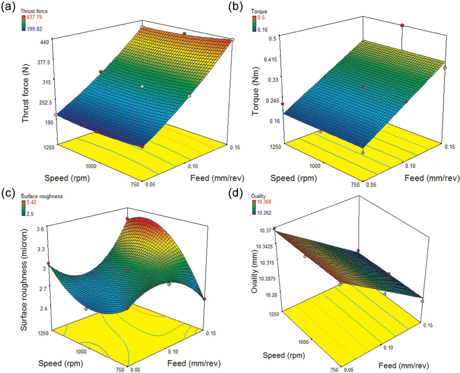
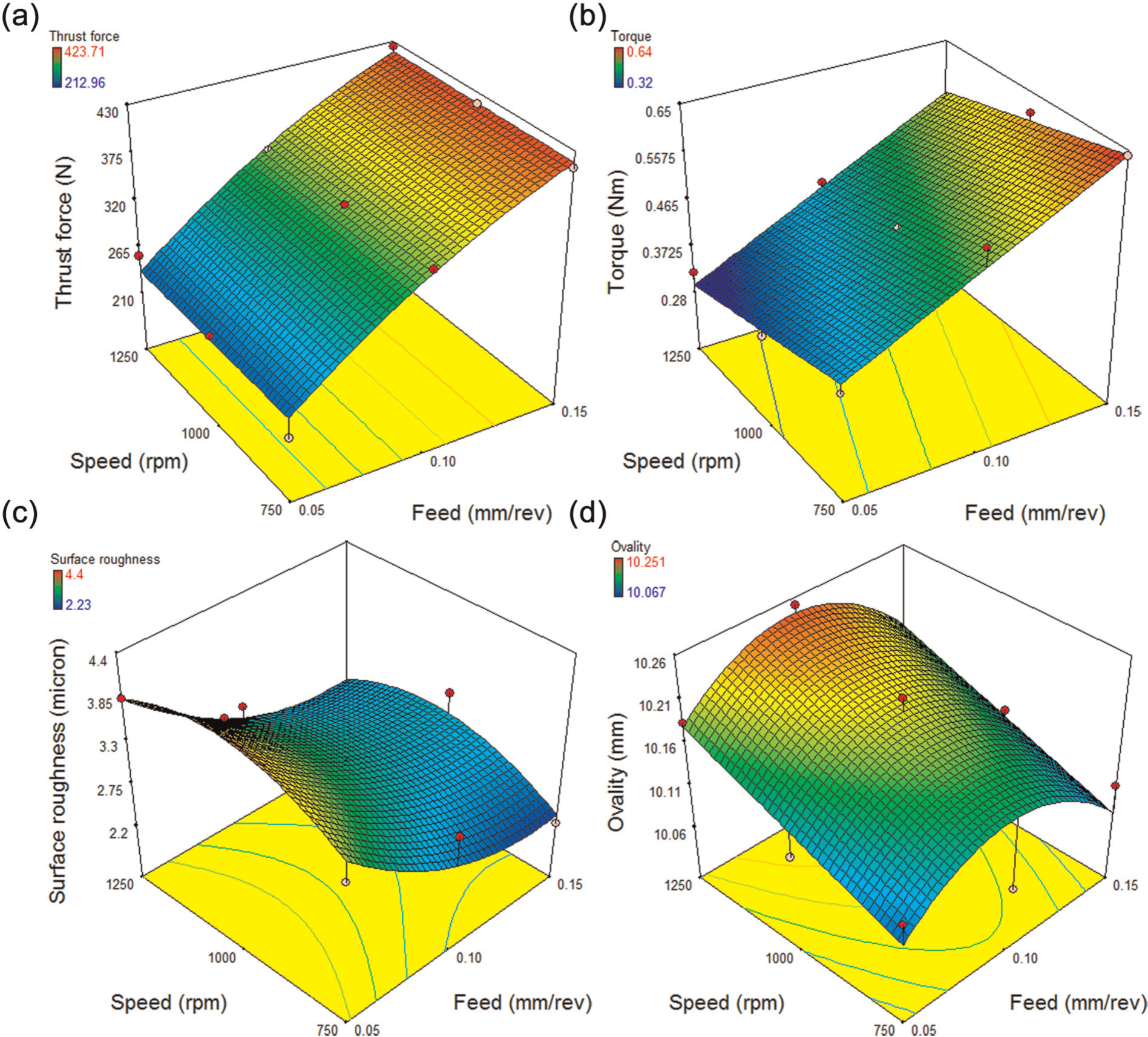
With twist drill minimum surface roughness (2.53 µm) results from the combination of medium value of feed (0.10 mm/rev) and medium value of speed (1000 r/min) and with ratio drill minimum surface roughness (1.77 µm) results from the combination of medium value of feed (0.10 mm/rev) and higher value of speed (1250 r/min). At high feed values, the removal of the fibres from the matrix is partially sheared leading to relatively high surface roughness. In contrast, at lesser feeds, a complete shearing of the fibre was occurred, resulting in a relatively good surface finish. 19 With an increase in feed, ovality of the drilled holes decreases for twist drill and remains almost constant for ratio drill. With an increase in speed, ovality remains almost constant for twist drill and increases for ratio drill. Since ratio drill gives lesser values for all the quality characteristics, it can be concluded that ratio drill performs better than twist drills in making through-holes of diameter of 10 mm. Figures 5 and 6 show the response of quality characteristics with process parameters for twist drill and ratio drill, respectively.
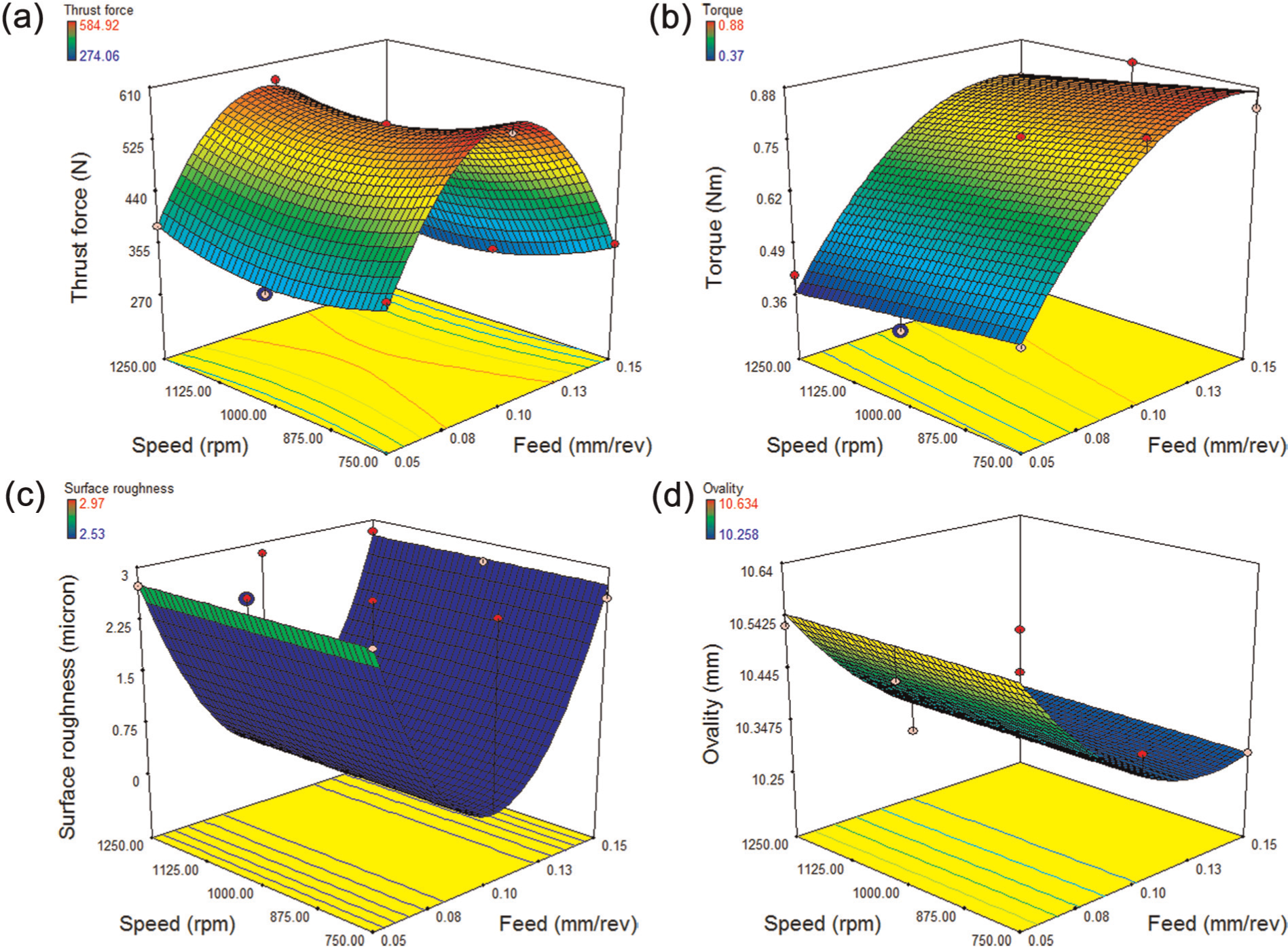
Interaction graphs of quality characteristics with process parameters in drilling pultruded composites (0°) with twist drill.
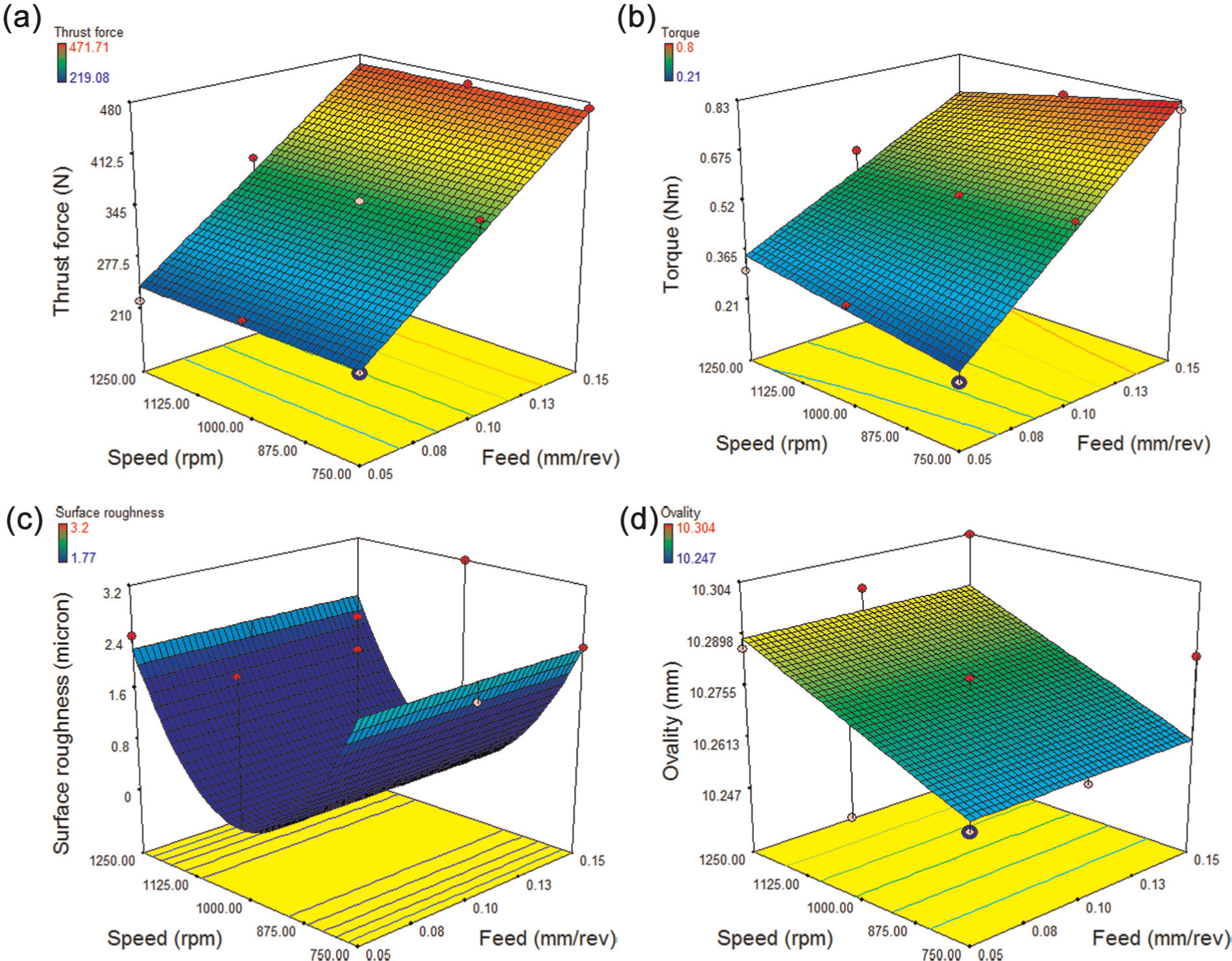
Interaction graphs of quality characteristics with process parameters in drilling pultruded composites (0°) with ratio drill.
Adequacy analysis of the model using analysis of variance
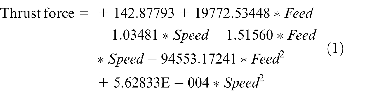
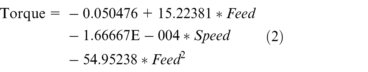
The following response surface models with significant model terms were obtained using RSM.
Twist drill


Ratio drill

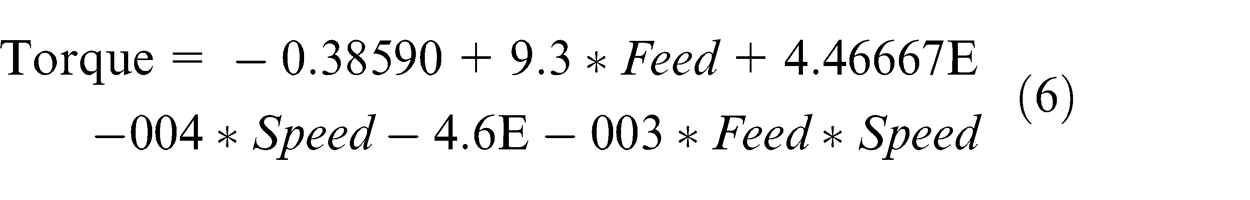


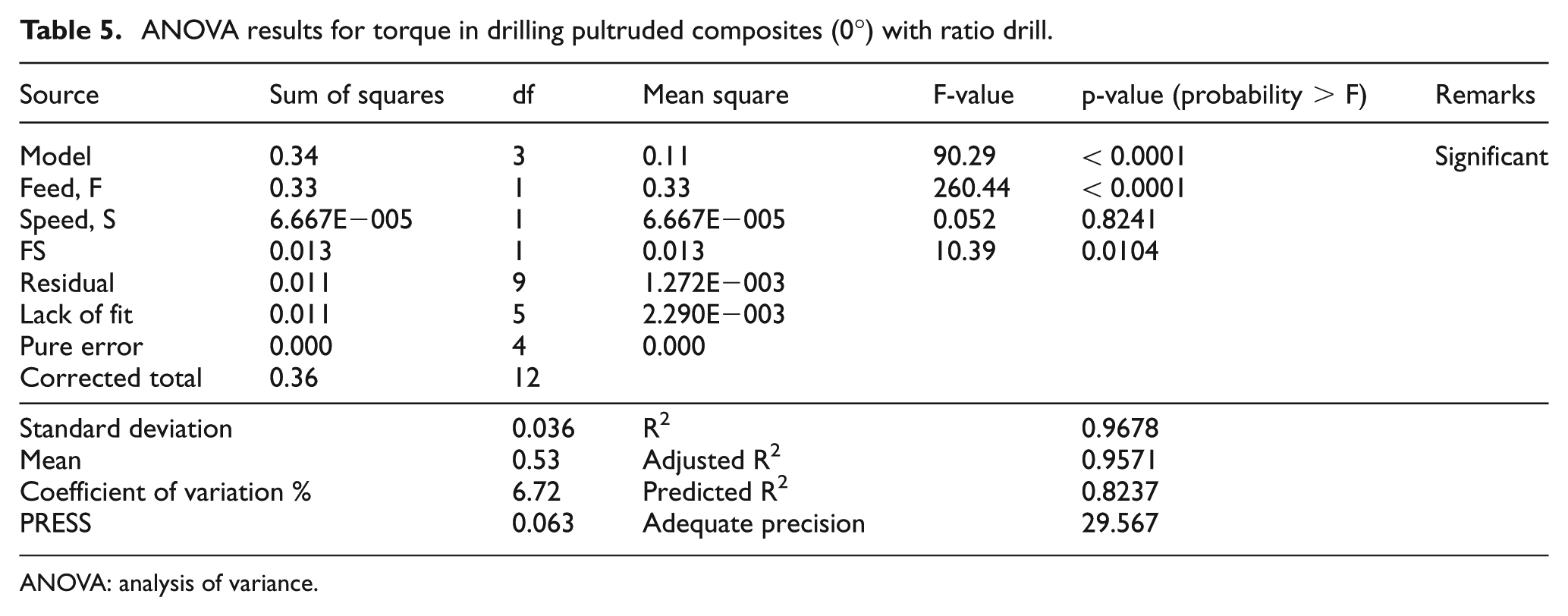
The adequacy of the response surface models (1)–(8) was tested using the analysis of variance (ANOVA) technique and the results of the regression model (6) fitting in the form of ANOVA are given in Table 5 as a typical example for adequate analysis. As per this technique, the calculated value of F-ratio of the developed model should be more than the tabulated value of the F - table, for 95% confidence level, for the model to be adequate.
ANOVA results for torque in drilling pultruded composites (0°) with ratio drill.
ANOVA: analysis of variance.
The Model F-value of 90.29 for torque implies the model is significant. There is only a 0.01% chance that a ‘Model F-Value’ this large could occur due to noise. Values of ‘Probability > F’ less than 0.05 indicate model terms are significant. For torque, F (feed) and FS (feed × speed) are significant model terms. Lack of fit is not significant as it is desired. A relatively lower value of the coefficient of variation indicates improved precision and reliability of the conducted experiments.
The determination coefficient (R2) indicates the goodness of fit of the model, that is, it indicates the agreement between experimental and predicted values. The determination coefficient indicates that only remaining percentage of the total variance is not explained by the model. The obtained R2 value of 0.9678 indicates a better fit of the model. The ‘Predicted R2’ of 0.8237 is in reasonable agreement with the ‘Adjusted R2’ of 0.9571. ‘Adequate Precision’ measures the signal-to-noise ratio. A ratio greater than 4 is desirable. The obtained ratio of 29.567 indicates an adequate signal. Therefore, the model (6) in terms of the actual factors for torque is adequate and can be used to navigate the design space. Similarly, the regression models (1)–(8) have been checked and found to be adequate.
Optimizing the process parameter levels in drilling thick pultruded composites (0°)
RSM is used to find the optimal set of process parameter levels that produce a maximum or minimum value of the response. 30 In the present investigation, the process parameter levels corresponding to the minimization of all the quality characteristics together are considered as optimum. The desirability graph (Figure 7(a)) shows that the process parameter level combination (0.053 mm/rev feed and 1059 r/min spindle speed) having the highest desirability of 0.639 is optimum for drilling pultruded composites (0° fibre orientation) with twist drill of diameter of 10 mm. The above optimal parameter levels for a twist drill predicts 378.075 N, 0.429 N m, 2.407 µm and 10.527 mm as thrust force, torque, surface roughness and ovality, respectively. Similarly, the desirability graph for ratio drill (Figure 7(b)) reveals that the process parameter level combination (0.05 mm/rev feed and 778 r/min spindle speed) having the highest desirability of 0.891 is optimum for drilling the composites. The above optimal parameter levels for ratio drill predict 239.20 N, 0.248 N m, 1.77 µm and 10.262 mm as thrust force, torque, surface roughness and ovality, respectively.
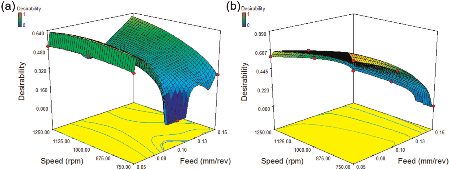
Desirability graph in drilling pultruded composites (0°) with (a) twist drill and (b) ratio drill.
Validation test
The purpose of the validation test is to confirm conclusions drawn during the analysis. 31 Once the model fit and predicted values at optimal levels have been arrived, the final step is to verify the agreement of regression model results with experimental values and thereby ensure the improvement of the quality characteristics at these levels. Two experimental runs with three trials each were conducted at the corresponding optimal values of process parameters. The obtained results of both experimental and predicted values show the same results within ±10% error. Hence, the above response surface models demonstrate a feasible and an effective way for the evaluation of quality characteristics within the selected range of parameter levels in drilling pultruded (0° fibre orientation) composites.
The average experimental values of quality characteristics obtained during optimal drilling of pultruded composites using twist drill and ratio drill are shown in Figure 8. It is observed that a ratio drill gives minimum value for all the quality characteristics than a twist drill. Thrust force, torque, surface roughness and ovality have been reduced by 36.19%, 42.11%, 23.49% and 2.34%, respectively, in the optimal drilling of pultruded composites using a ratio drill as compared to that of the twist drill. It can be seen from the confirmation experimental results that the quality characteristics have greatly been improved by the optimal drilling parameter levels. The average range of surface roughness in drilling is 1.6–6.3 µm 32 and the value of surface roughness obtained with optimal process parameter levels falls well within this average range.
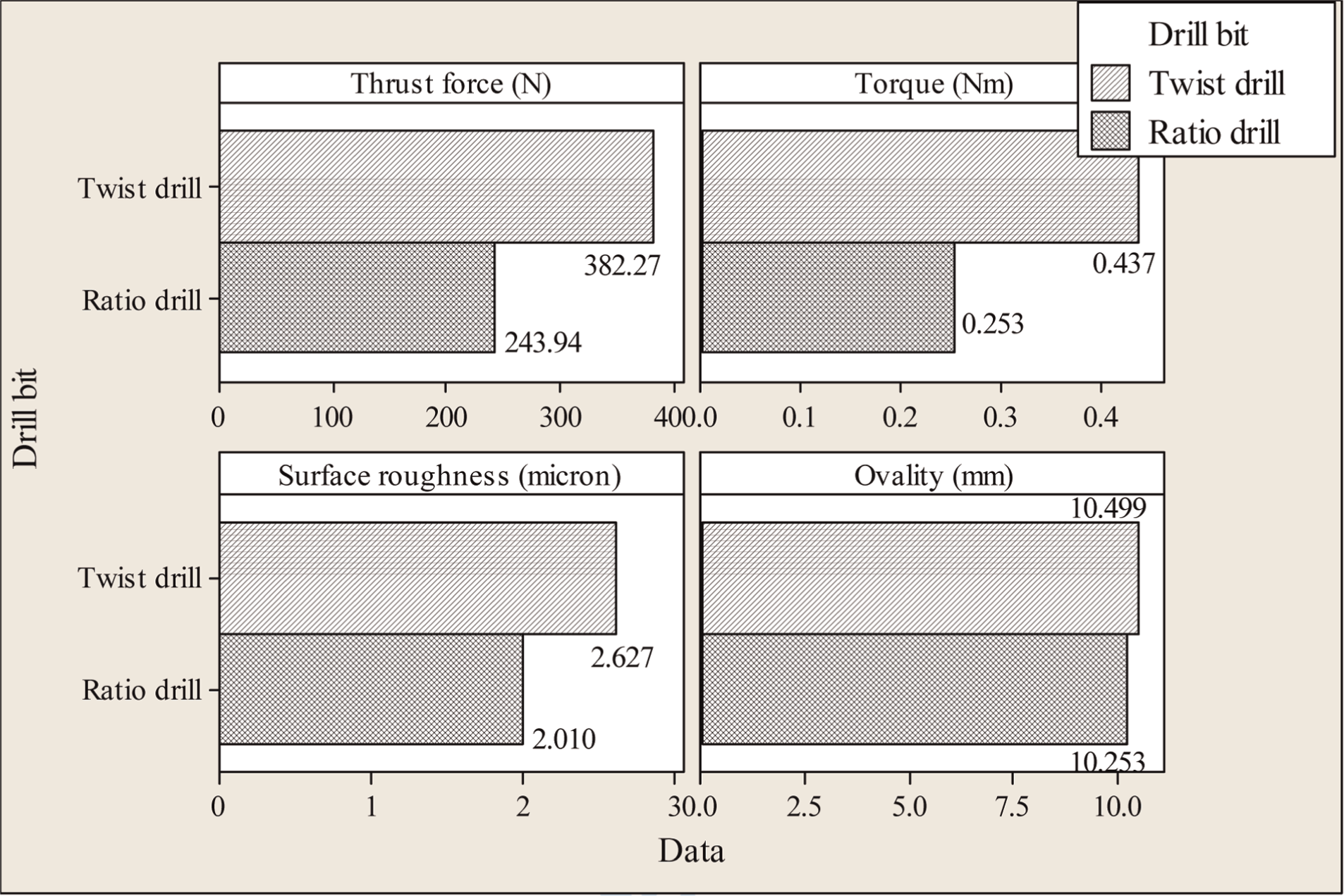
Average experimental values of quality characteristics at optimal parameter levels in drilling pultruded composites (0°).
Pultruded composite with 90° fibre orientations
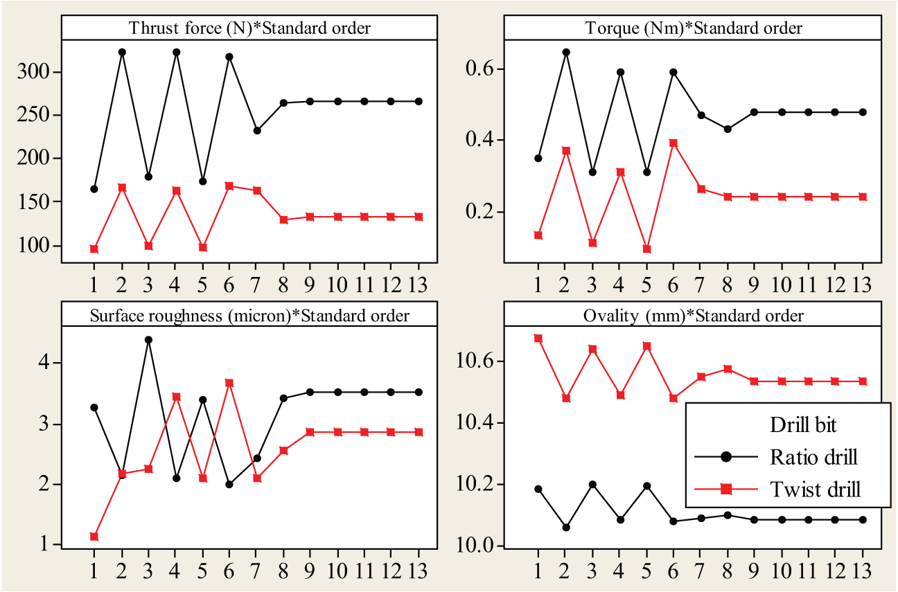
Two twist drills have been used for making 27 holes. The average maximum flank wear of first twist drill after making 14 holes was 0.027 mm and that of second twist drill after making remaining holes was also 0.027 mm. Two ratio drills have been used for making 27 holes. The average maximum flank wear of first ratio drill after making 14 holes was 0.021 mm and that of second ratio drill after making remaining holes was 0.020 mm. The effect of 0.027 and 0.021 mm flank wear on hole quality will be negligible, and hence, tool wear is not considered in this study. 28 From Figure 9, a plot of experimental results, it is observed that twist drill gives more number of minimum values for all the quality characteristics (except ovality) than that of ratio drill within the range examined, which is desirable towards defect controlled drilling. Also, if torque and surface roughness are considered separately, twist drill performs much better than ratio drill. When ovality is considered separately, ratio drill performs much better than twist drill and this may be attributed to its special point geometry (relieved cone). When thrust force considered separately, ratio drill performs better than twist drills at higher feed values.
Response graph of quality characteristics for process parameters in drilling pultruded composite (90°).
With an increase in feed, thrust force and torque increases for both the drills. As thrust force increases, it can be concluded that both the drills do not produce thermal softening of polymeric matrix at higher speed and higher feed condition. Increase in torque may be due to the increasing cross-sectional area of the undeformed chip. 29 With an increase in speed, thrust force and torque almost remain constant for both the drills.
With an increase in feed, surface roughness of the side walls of the drilled hole for twist drill and ratio drill increases and decreases, respectively. At high feed values, the removal of the fibres from the matrix is partially sheared leading to relatively high surface roughness. In contrast, at lesser feeds, a complete shearing of the fibre was occurred, resulting in a relatively good surface finish. 19 It can be concluded that the special geometry design of ratio drill produces a relatively complete shearing of fibre at higher feeds which is in contrast to Khashaba et al. 19 With an increase in speed, surface roughness and ovality almost remain constant for both the drills. With an increase in feed, ovality of the drilled holes decreases for both the drills. Since ratio drill gives lesser values of surface roughness and ovality, it can be concluded that ratio drill performs better than twist drills in making through-holes of diameter of 10 mm. Figures 10 and 11 show the response of quality characteristics with process parameters for twist drill and ratio drill, respectively. Also, it is observed that the orientation of fibre in pultruded composites, 0° and 90° with respect to the drill, produces lesser surface roughness and lesser ovality, respectively, with ratio drill.
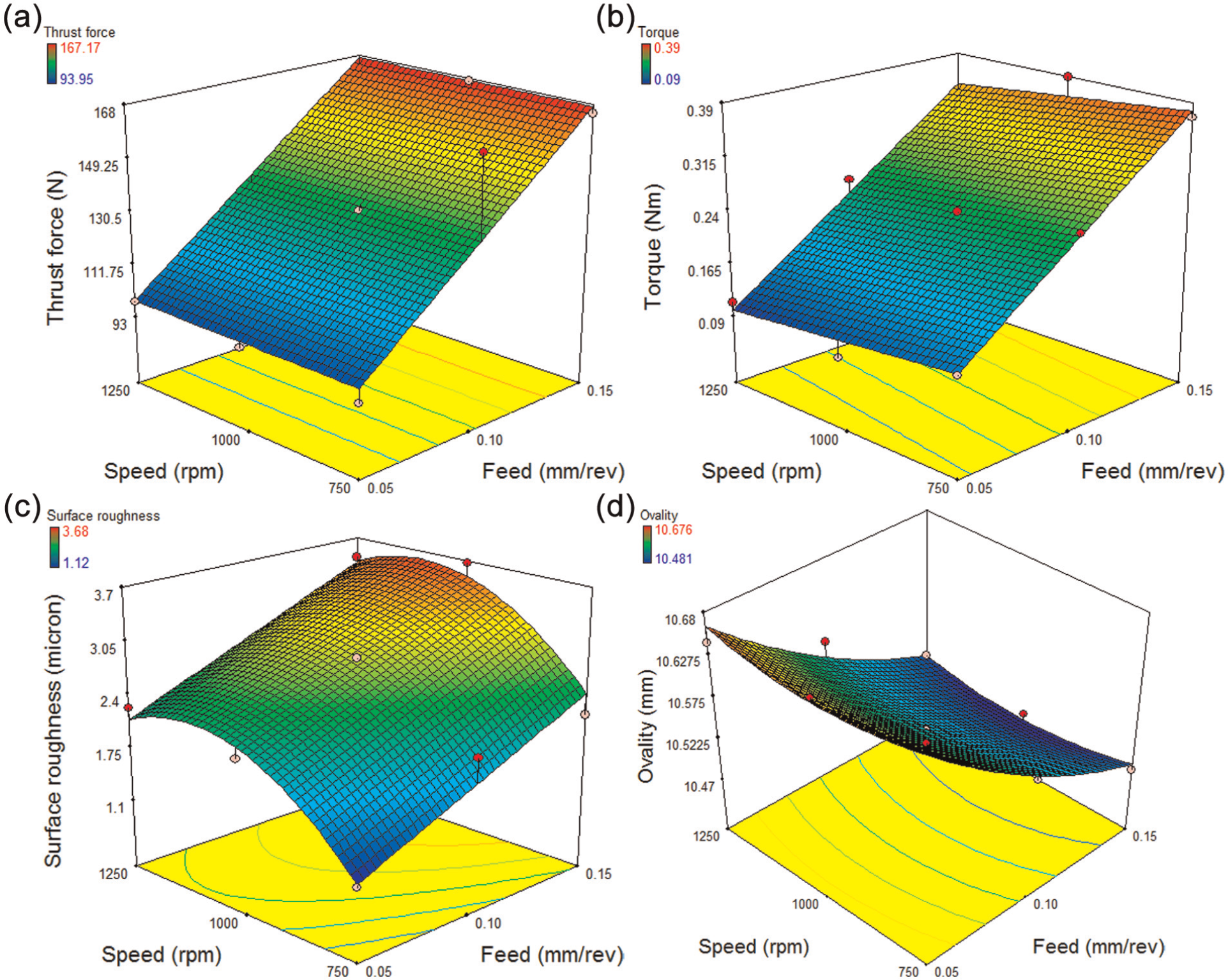
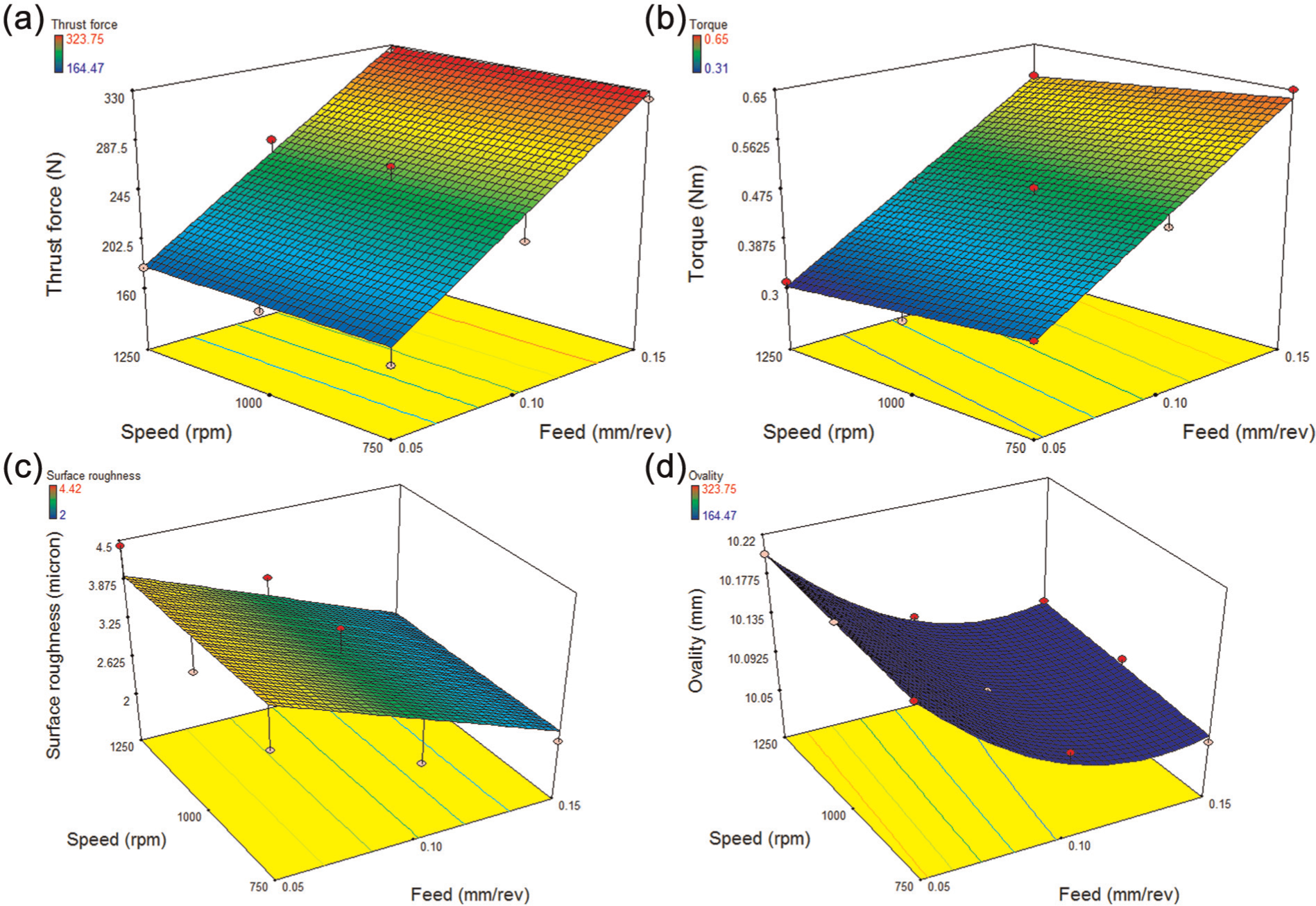
Interaction graphs of quality characteristics with process parameters in drilling pultruded composites (90°) with twist drill.
Interaction graphs of quality characteristics with process parameters in drilling pultruded composites (90°) with ratio drill.
Adequacy analysis of the model using ANOVA
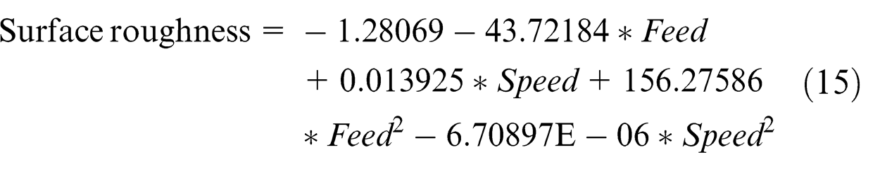
The following response surface models with significant model terms were obtained using RSM.
Twist drill

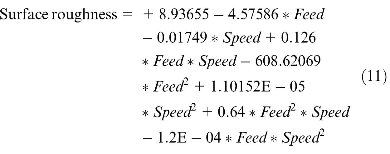

Ratio drill


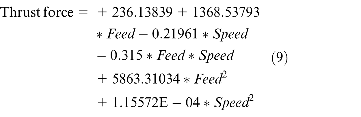
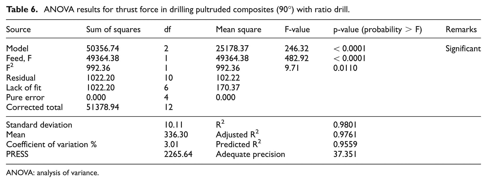
The adequacy of the response surface models (9)–(16) was tested using the ANOVA technique and the results of the regression model (13) fitting in the form of ANOVA are given in Table 6 as a typical example for adequate analysis. The Model F-value of 246.32 for thrust force implies the model is significant. There is only a 0.01% chance that a ‘Model F-Value’ this large could occur due to noise. For thrust force, F and F2 are significant model terms. Lack of fit is not significant as it is desired. A relatively lower value of the coefficient of variation indicates improved precision and reliability of the conducted experiments.
ANOVA results for thrust force in drilling pultruded composites (90°) with ratio drill.
ANOVA: analysis of variance.
The obtained R2 value of 0.9801 indicates a better fit of the model. The ‘Predicted R2’ of 0.9559 is in reasonable agreement with the ‘Adjusted R2’ of 0.9761. ‘Adequate Precision’ of 37.351 indicates an adequate signal. Therefore, the model (13) in terms of the actual factors for thrust force is adequate and can be used to navigate the design space. Similarly, the regression models (9)–(16) have been checked and found to be adequate.
Optimizing the process parameter levels in drilling thick pultruded composites (90°)
The desirability graph (Figure 12(a)) shows that the process parameter level combination (0.091 mm/rev feed and 1250 r/min spindle speed) having the highest desirability of 0.611 is optimum for drilling thick pultruded composites with twist drill of diameter of 10 mm. The above optimal parameter levels for a twist drill predict 279.24 N, 0.27 N m, 2.72 µm and 10.325 mm as thrust force, torque, surface roughness and ovality, respectively. Similarly, the desirability graph (Figure 12(b)) for ratio drill reveals that the process parameter level combination (0.05 mm/rev feed and 750 r/min spindle speed) having the highest desirability of 0.691 is optimum for drilling the composites. The above optimal parameter levels for ratio drill predict 236.15 N, 0.39 N m, 3.59 µm and 10.091 mm as thrust force, torque, surface roughness and ovality, respectively.
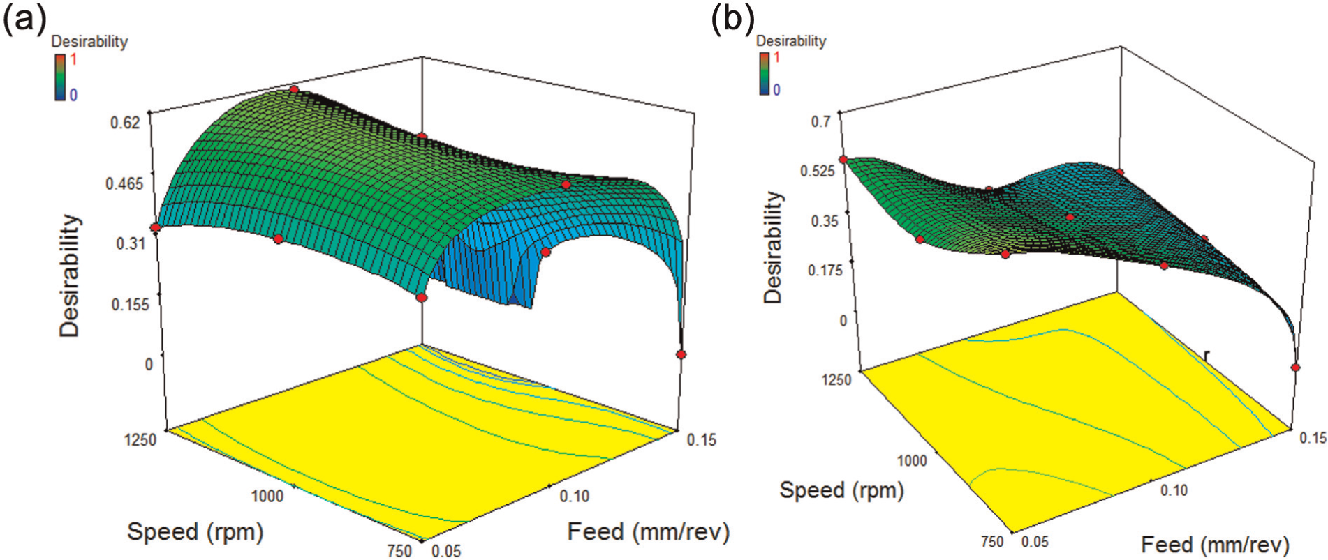
Desirability graph in drilling pultruded composites (90°) with (a) twist drill and (b) ratio drill.
Validation test
Two experimental runs with three trials each were conducted at the corresponding optimal values of process parameters. The obtained results of both experimental and predicted values show the same results within ±10% error. Hence, the above response surface models demonstrate a feasible and an effective way for the evaluation of quality characteristics within the selected range of parameter levels in drilling thick pultruded (90° fibre orientation) composites.
The average experimental values of quality characteristics, obtained during optimal drilling of thick pultruded composites using twist drill and ratio drill, are shown in Figure 13. Torque and surface roughness have been reduced by 35.14% and 19.52%, respectively, at the optimal drilling of thick pultruded composites using a twist drill as compared to that of ratio drill. Thrust force and ovality have been reduced by 21.20% and 1.83%, respectively, at the optimal drilling of thick pultruded composites using a ratio drill as compared to that of the twist drill. It can be seen from the confirmation experimental results that the quality characteristics have greatly been improved by the optimal drilling parameter levels. The values of surface roughness obtained with optimal process parameter levels fall well within the average range. 32 Ovality is caused due to overcut, which affects the bearing strength more than that of surface roughness. Therefore, giving more importance to ovality than surface roughness, one can conclude that the ratio (special geometry) drill is better than the twist (standard geometry) drill at their optimal parameter levels to make 10 mm holes in thick pultruded composites.
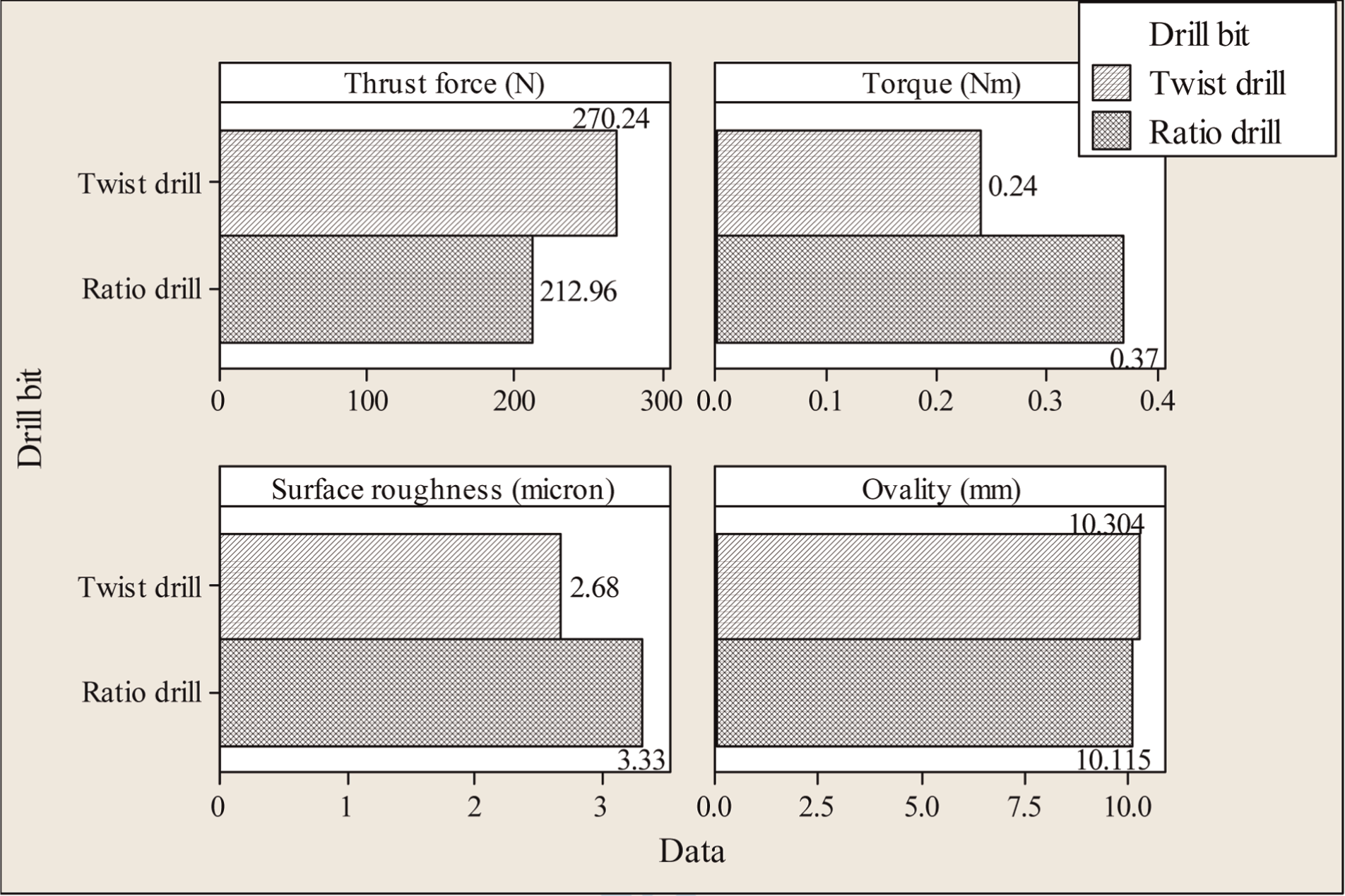
Average experimental values of quality characteristics at optimal parameter levels in drilling pultruded composites (90°).
SMC composite with 90° fibre orientations
Two twist drills have been used for making 27 holes. The average maximum flank wear of first twist drill after making 14 holes and that of second twist drill after making remaining holes was negligible. Two ratio drills have been used for making 27 holes. The average maximum flank wear of first ratio drill after making 14 holes was 0.029 mm and that of second ratio drill after making remaining holes was 0.029 mm. The effect of 0.029 mm flank wear on hole quality will be negligible and hence, tool wear is not considered in this study. 28 From Figure 14, a plot of experimental results, it is observed that twist drill gives minimum values for the quality characteristics (thrust force, torque and surface roughness) than that of ratio drill within the range examined, which is desirable towards defect controlled drilling. The reduction in thrust force, torque and surface roughness observed in the case of twist drill can be attributed to its standard geometry.
Response graph of quality characteristics for process parameters in drilling SMC composite (90°).
When surface roughness considered separately, ratio drill performs better than twist drills at higher feed and speed values. With an increase in feed, thrust force and torque increases for both the drills. This may be due to the increasing cross-sectional area of the undeformed chip. 29 With an increase in speed, thrust force and torque almost remains constant for both the drills. With an increase in feed and speed, surface roughness (Ra) increases for a twist drill, whereas for a ratio drill, surface roughness decreases with an increase in feed and remains almost constant with an increase in speed. At high feed values, the removal of the fibres from the matrix is partially sheared leading to relatively high surface roughness. In contrast, at lesser feeds, a complete shearing of the fibre was occurred, resulting in a relatively good surface finish. 19 It can be concluded that the special geometry design of ratio drill produces a complete shearing of fibre even at higher feeds which is in contrast to Khashaba et al. 19 With an increase in feed, ovality decreases for both the drills. With an increase in speed, ovality almost remains constant for both the drills. Ratio drill gives much lesser ovality than a twist drill because of its special point geometry (relieved cone). Figures 15 and 16 show the response of quality characteristics with process parameters for twist drill and ratio drill, respectively. Since twist drill gives lesser values of thrust force, torque and surface roughness, it can be concluded that twist drill performs better than ratio drill in making through-holes of diameter of 10 mm.
Interaction graphs of quality characteristics with process parameters in drilling SMC composites with twist drill.
Interaction graphs of quality characteristics with process parameters in drilling SMC composites with ratio drill.
Adequacy analysis of the model using ANOVA
The following response surface models with significant model terms were obtained using RSM.
Twist drill


Ratio drill


The adequacy of the response surface models (17)–(24) was tested using the ANOVA technique and the results of the regression model (17) fitting in the form of ANOVA are given in Table 7 as a typical example for adequate analysis.
ANOVA results for thrust force in drilling SMC composites with twist drill.
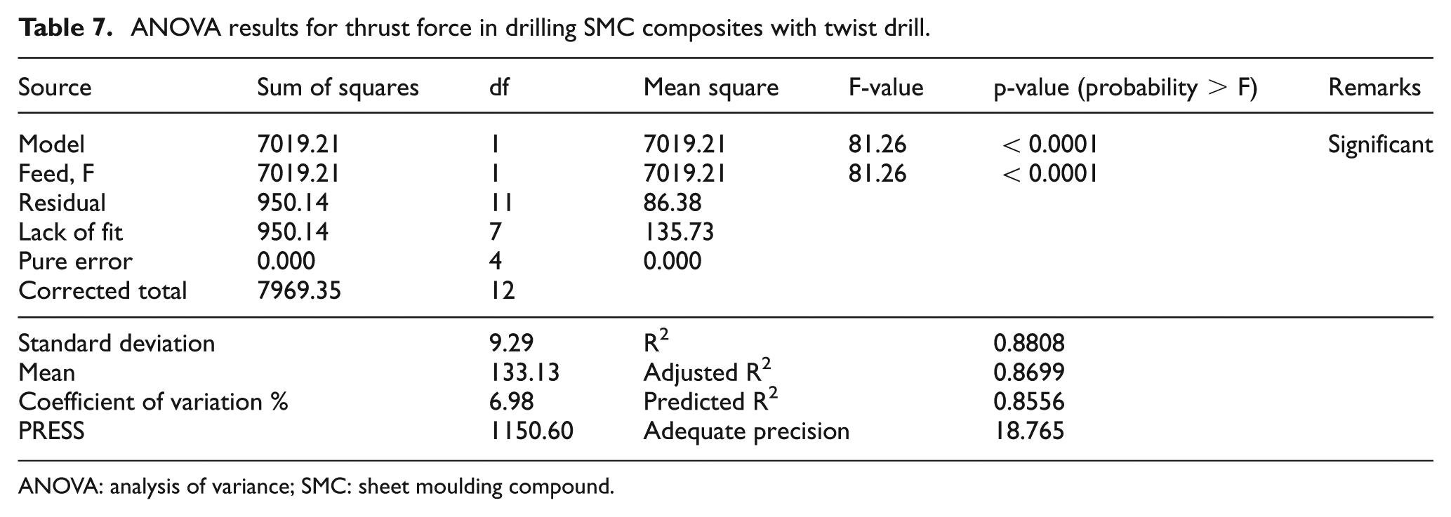
ANOVA: analysis of variance; SMC: sheet moulding compound.
The Model F-value of 81.26 for thrust force implies the model is significant. There is only a 0.01% chance that a ‘Model F-Value’ this large could occur due to noise. For thrust force, F (feed) is a significant model term. Lack of fit is not significant as it is desired. A relatively lower value of the coefficient of variation indicates improved precision and reliability of the conducted experiments.
The obtained R2 value of 0.8808 indicates a better fit of the model. The ‘Predicted R2’ of 0.8556 is in reasonable agreement with the ‘Adjusted R2’ of 0.8699. ‘Adequate Precision’ of 18.765 indicates an adequate signal. Therefore, the model (17) in terms of the actual factors for thrust force is adequate and can be used to navigate the design space. Similarly, the regression models (17)–(24) have been checked and found to be adequate.
Optimizing the process parameter levels in drilling SMC composites
The desirability graph (Figure 17(a)) shows that the process parameter level combination (0.074 mm/rev feed and 750 r/min spindle speed) having the highest desirability of 0.615 is optimum for drilling SMC composites with twist drill of diameter of 10 mm. The above optimal parameter levels for a twist drill predict 115.22 N, 0.19 N m, 1.46 µm and 10.608 mm as thrust force, torque, surface roughness and ovality, respectively. Similarly, the desirability graph for ratio drill (Figure 17(b)) reveals that the process parameter level combination (0.091 mm/rev feed and 1250 r/min spindle speed) having the highest desirability of 0.573 is optimum for drilling the composites. The above optimal parameter levels for ratio drill predict 241.09 N, 0.42 N m, 3.29 µm and 10.106 mm as thrust force, torque, surface roughness and ovality, respectively.
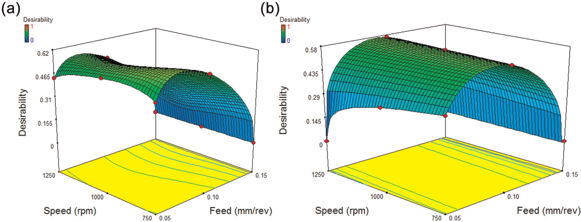
Desirability graph in drilling SMC composites with (a) twist drill and (b) ratio drill.
Validation test
Two experimental runs with three trials each were conducted at the corresponding optimal values of process parameters. The obtained results of both experimental and predicted values show the same results within ±10% error. Hence, the above response surface models demonstrate a feasible and an effective way for the evaluation of quality characteristics within the selected range of parameter levels in drilling SMC composites.
The average experimental values of quality characteristics obtained during optimal drilling of SMC composites using twist drill and ratio drill are shown in Figure 18. It is observed that twist drill gives minimum value for all the quality characteristics (except ovality) than ratio drill. Thrust force, torque and surface roughness have been reduced by 50.47%, 53.49% and 53.22%, respectively, in the optimal drilling of SMC composites using a twist drill as compared to that of a ratio drill. Also, it is observed that ovality of the drilled holes obtained through twist drill is slightly greater (5.1%) than that of ratio drill. It can be seen from the confirmation experimental results that the quality characteristics have greatly been improved by the optimal drilling parameter levels. The value of surface roughness obtained with optimal process parameter levels falls well within the average range. 32
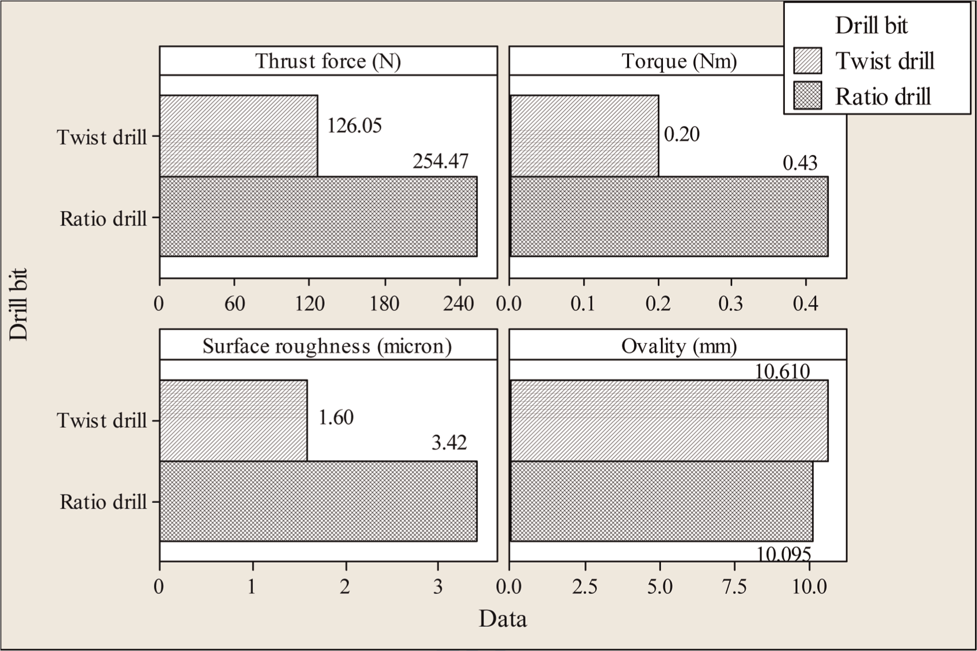
Average experimental values of quality characteristics at optimal parameter levels in drilling SMC composites.
Conclusion
This article has described the relative influence of drilling process parameters (feed and spindle speed) on quality characteristics (thrust force, torque, surface roughness and ovality) for standard and special geometric design of a drill body in both SMC and pultruded (0° and 90° fibre orientation) thick GFRP composites. Drilling experiments were carried out using coated tungsten carbide drills (twist drill and ratio drill) of diameter of 10 mm. From this investigation, the following important conclusions were derived:
Twist drill produces thermal softening of polymeric matrix at higher speed and higher feed condition only in pultruded composites having 0° fibre orientations with respect to the drill and this is observed with thrust force values.
Ratio drill gives lesser ovality (imperfectness of circularity) than a twist drill because of its special point geometry (relieved cone).
Special point geometry of ratio drill produces a relatively complete shearing of fibre and thereby lesser surface roughness at higher feeds.
The orientation of fibre in pultruded composites, 00 and 900 with respect to the drill, produces lesser surface roughness and lesser ovality, respectively, with ratio drill.
Ratio drill performs better than a twist drill in drilling the pultruded composites having 00 and 900 fibre orientations with respect to the drill. Twist drill performs better than ratio drill in drilling the SMC composites.
Ratio drill is subjected to less wear than a twist drill while drilling pultruded composites (00 and 900 fibre orientation). Negligible wear in twist drill was observed while drilling SMC composites.
The process parameter level combination (0.05 mm/rev feed and 778 r/min spindle speed) having the highest desirability of 0.891 is optimum for drilling the pultruded composites (00) with ratio drill.
The process parameter level combination (0.05 mm/rev feed and 750 r/min spindle speed) having the highest desirability of 0.691 is optimum for drilling the pultruded composites (900) with ratio drill.
The process parameter level combination (0.074 mm/rev feed and 750 r/min spindle speed) having the highest desirability of 0.615 is optimum for drilling the SMC composites with a twist drill.
Footnotes
Acknowledgements
The authors are grateful to M/s. Sunrise Fibre Glass Industries, Bengaluru, India for supplying the composite materials for experimentation. The authors are thankful to Sandvik Coromant India and Guhring India Pvt. Ltd. for supplying the drill bits used in these experiments. Also, the authors are thankful for METMECH Engineers, Chennai and Opus Precision Instruments Pvt. Ltd., Chennai for assisting in taking surface roughness and ovality measurements, respectively.
Declaration of conflicting interests
The authors declare that there is no conflict of interest.
Funding
This research received no specific grant from any funding agency in the public, commercial or not-for-profit sectors.