
Abstract
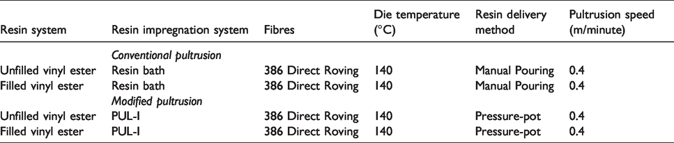
The focus of the current research was to demonstrate a modified pultrusion technique at an industrial site using a commercial production machine. In this instance, the conventional resin bath was replaced by a custom-designed compact impregnation unit. The dimensions of the impregnator were 310 mm × 400 mm × 9 mm. The relatively short length of the impregnator, when compared to a 5 litre resin bath, meant that it had to be efficient in impregnating the reinforcing fibre bundles. This was achieved using a fibre spreading unit and a facility to inject the resin under low-pressure. The design basis for the fibre spreading unit and the impregnator are presented along with the methodology that was used to select the pultrusion speed and die temperature. The pultrusion experiments were performed using filled and unfilled vinyl ester resin and E-glass fibres. The profile of the 0.5 metre-long die was rectangular with dimensions of 32 mm × 2.2 mm. The fibre spreading unit and the impregnator were retrofitted to the pultrusion line with ease. The physical, mechanical and thermo-mechanical properties were determined for the pultruded composites using the resin bath and the modified technique. The properties of the latter were found to be equivalent or marginally superior when compared to the resin bath-based production method. However, in the modified pultrusion technique, when compared to conventional resin bath-based pultrusion, the volume of waste resin generated was 97% lower. The volume of solvent required to clean the equipment after production was reduced by 90%.
Introduction
Pultrusion is an established manufacturing technique that is used to produce continuous fibre reinforced composite profiles of a constant cross-section. Examples of typical pultruded profiles include rods, hollow tubes, flat sheets and beams. The term “fibre spreading” is used here in the context of spreading the filaments in a bundle prior to impregnation. 1 Fibre spreading results in a decrease in the thickness of the bundle with a concomitant increase in the width. 2 This enhances the through-thickness impregnation rate. 3 A schematic illustration of a typical resin bath-based pultrusion production process is shown in Figure 1(a) and a magnified view of the resin bath is presented in Figure 1(b).
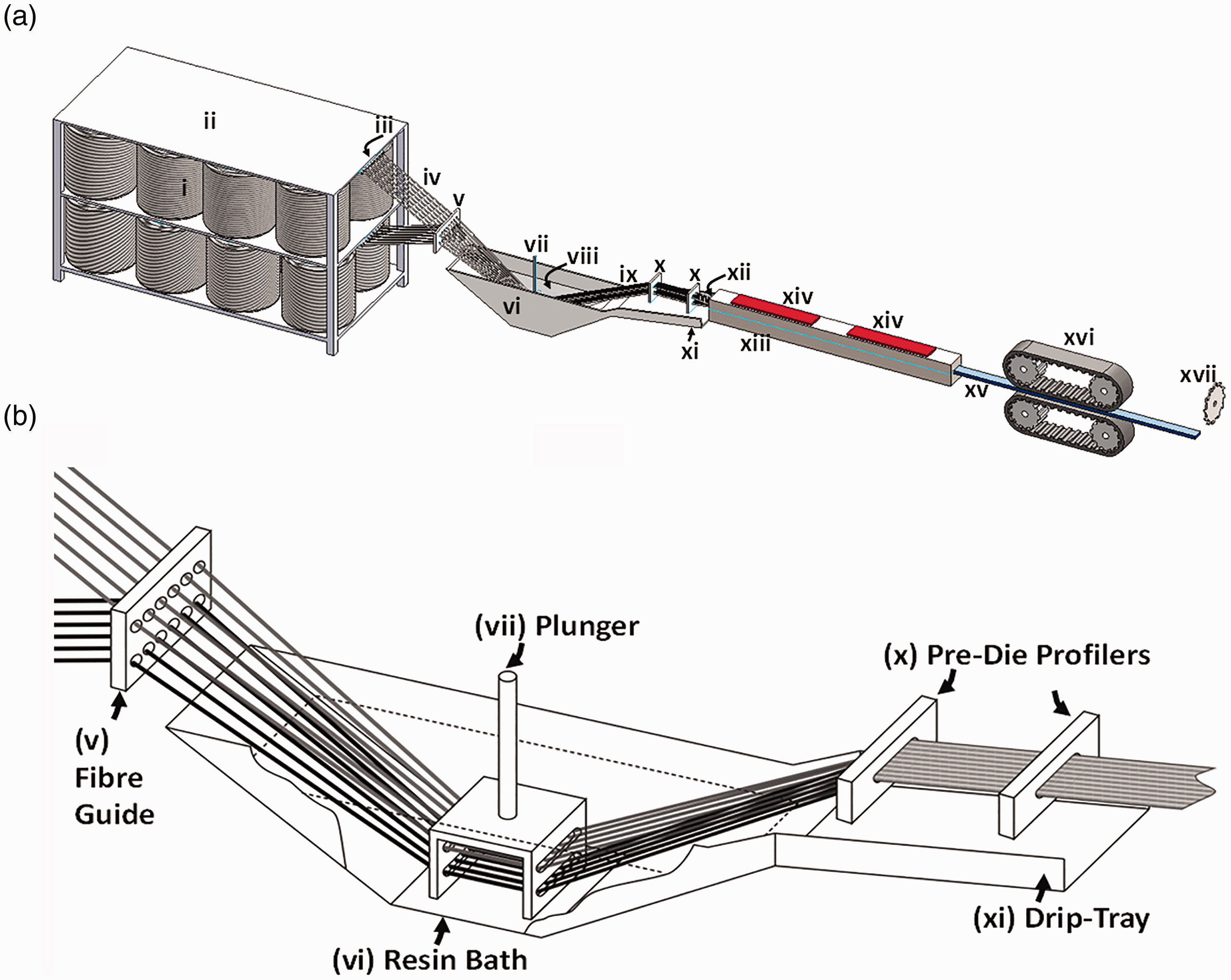
(a) Schematic illustration of a conventional resin bath-based pultrusion process. The presence of reinforcing mats that are fed into the resin bath (to enhance the transverse properties of the composite) is not shown. (b) Magnified view of the resin bath.
The following section presents a brief discussion on the key components highlighted in Figure 1(a) and (b). The creels or spools of fibre-(i) are stacked on a creel stand-(ii) and the individual bundles are unwound from the bore (this is generally referred to as centre-pull payout). The individual bundles are guided through a series of fibre guides-(iii) to configure them spatially to the required trajectory. The arrays of fibres-(iv) are fed through a further set of guides-(v) into the resin bath-(vi) via a “plunger”-(vii). The plunger permits the array of fibres to be lowered or raised into a resin bath-(vi) where they soak up the resin system-(vii) when immersed. The fibres at this stage are effectively over-impregnated. The impregnated fibre bundles-(ix) are directed to sets of pre-die guides-(x) that resemble the geometry of the die entrance but with slightly larger dimensions. A fair volume of the excess resin on the fibre bundles is squeezed out as they traverse these pre-die guides and enter the die. The resin that is squeezed out at the pre-die guides-(x) and the entrance to the die-(xii) is channelled back to the resin bath via a drip-tray-(xi). The impregnated fibres are directed into a split die-(xiii) with surface-mounted external heaters-(xiv). The external heaters are used to create a temperature profile along the length of the die. The impregnated fibre bundles are cross-linked or cured within the heated die and the composite-(xv) with the profile of the die is created. The solid composite profile is hauled off-(xvi) and sectioned to the required length using a mechanical cutter-(xvii).
According to a report by Lucintel, the global composite materials market is predicted to reach U$41.8 billion by 2025. The global end-product sector is estimated to attain U$116.6 billion by 2025. 4 Considering the global pultrusion market, it is predicted to reach U$3 billion by 2023. 5 The predicted growth for another manufacturing process that involves the impregnation of continuous fibres is filament winding. Two key products manufactured using filament winding are pipes and pressure vessels. The composites pipe market is forecast to expand at a compound annual growth rate of 3.2% from 2019 to 2024 and it is predicted to reach U$4,363 million by 2024. 6 According to a report by Zion Market Research, the composite liquid petroleum gas cylinder market itself was stated to be worth U$131 million in 2018 and it is forecast to grow to U$249 million by 2025. 7 With reference to pultrusion, technologies that can potentially have a positive impact on the market share include, (a) innovations to enable an increase in the pultrusion rate, (b) integrated sensor systems for on-line process monitoring and structural integrity assessment and (c) fast-curable resins. Since the patent by Goldsworthy in 1959, 8 the continued economic importance of pultrusion over the last three decades has resulted in significant attention being paid to process modification9–16 and optimisation via modelling.9,17–31
The current authors reported previously on a modified pultrusion process 32 where the resin bath was replaced with a purpose-designed low-pressure resin impregnation unit. In summary, with reference to the mode of operation of the modified pultrusion technique, the resin and hardener are stored separately and pumped on demand via a pair of precision gear pumps to a static mixer. The throughput volume from each pump is pre-calibrated to deliver the required stoichiometric ratio for the resin system. The mixed resin system from the static mixer is directed to the resin impregnation unit where the partially spread bundles are impregnated. The positions of the custom-designed fibre spreading and impregnation units are shown in Figure 2. The current paper reports on the evaluation of this modified pultrusion technique on a commercial pultrusion machine at an industrial site using a filled resin system.
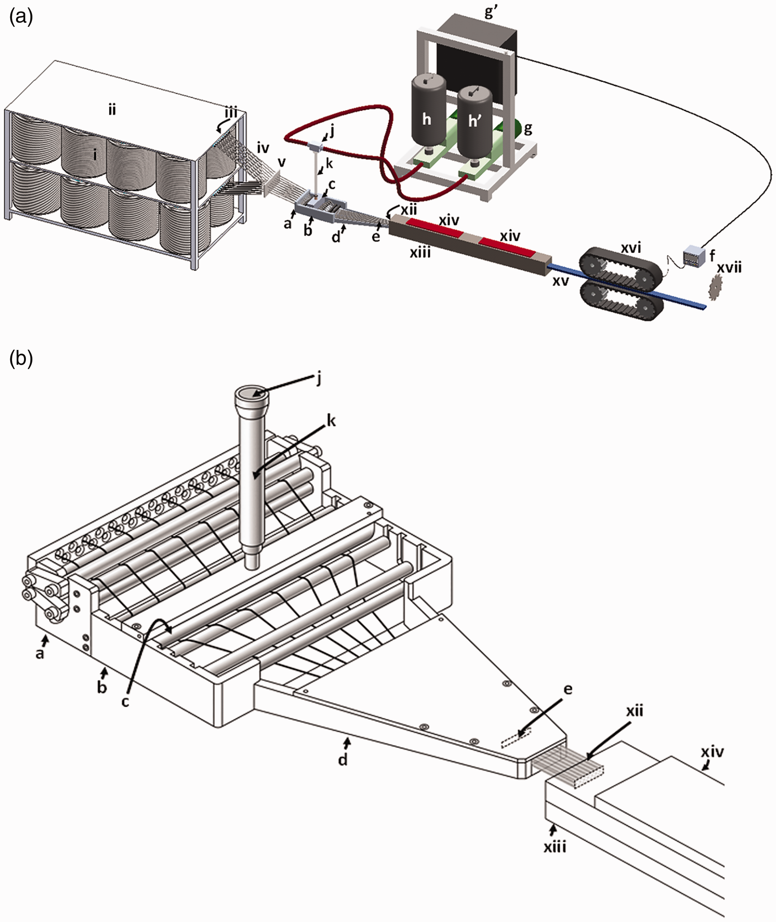
(a) Schematic illustration of the modified low-pressure injection pultrusion technique. (b) Magnified view of the resin impregnator.
The focus of the research was four-fold. Firstly, it was to demonstrate that the modified pultrusion equipment could be retrofitted on an industrial pultrusion machine without requiring any modification to the original machinery. Secondly, since unfilled resins were used in the laboratory trials, 32 it was necessary to demonstrate that filled resins could be used with this modified pultrusion technique in an industrial setting. Thirdly, it was necessary to demonstrate that the physical and mechanical properties of composites manufactured using the modified pultrusion technique did not result in any degradation of the physical, mechanical and thermo-mechanical properties. Finally, data were gathered on-site to verify the “green credentials” of the modified pultrusion method when compared to the conventional resin bath-based production technique.
Description of the modified low-pressure impregnation pultrusion process
When compared to the conventional pultrusion technique (see Figure 1(a)), items (i) to (v) and (xii) to (xvii) in the modified method (as illustrated in Figure 2(a)) remain the same. In the modified pultrusion method, the resin bath shown in Figure 1 is replaced with a compact fibre spreading unit and a low-pressure resin impregnator or a pressure-pot (containing the mixed resin and hardener - not shown in Figure 2).
With reference to Figure 2(b), the arrays of fibre bundles are guided through eyelets to the fibre spreading unit-(a). The primary function of the fibre spreading unit is to initiate partial de-cohesion of the binder and to enable the lateral spreading of the filaments with a concomitant decrease in the thickness.1,2 The details of this unit were presented previously. 32 The array of fibres are directed under the resin impregnation unit-(b) where the partially spread fibres are impregnated at the resin delivery head-(c). In the modified pultrusion technique, the drip tray that is used with conventional pultrusion is replaced by an inclined and integrated platform that serves as the resin-drip tray and the fibre compaction zone-(d), before the fibres are directed to the heated die. The integrated platform is inclined to permit the resin that is squeezed out from the bundles at the fibre pre-guide-(e) to flow back under gravity to the impregnation zone. In effect, this serves as a miniature reservoir and it aids resin pick-up by the fibre bundles below the impregnator. Hence, under ideal processing conditions, the dripping of resin from the impregnated fibre bundles as they enter the die is minimised. The impregnated and aligned fibre bundles enter the die and the items (xii-xvii) mentioned previously are identical. However, in this instance, a feedback control system-(f) is used to synchronise the haul-off unit to the pumping speed of two precision gear pumps-(g) where each independently services a reservoir containing the resin-(h) and the hardener-(h’). The two pumps are controlled independently by a master control unit-(g’). Since the pumps serving the resin and hardener reservoir are controlled independently, it is possible to set the required stoichiometry and the throughput rates. The feedback control system ensures that the pumping of the resin and hardener is synchronised to the haul-of unit. The resin and hardener are pumped on demand to a manifold-(j) and the two streams are fed to a static mixer-(k). The mixed resin system is supplied to the resin delivery head-(c).
The fibre spreading unit and the resin impregnator were designed to fulfil the following requirements.
Fibre spreading unit: This unit was designed to be integrated into a pultrusion line where the fibre bundles are spread partially by passing them in a serpentine manner through a series of rollers. This had the effect of partially breaking up the binder and permitting the lateral spreading of the filaments in the bundle; at the same time, the thickness of each bundle is reduced. This enables the through-thickness impregnation of the resin to be accelerated. 3 The fibre spreading unit also served to present a ribbon of fibre bundles, with minimal segmentation, to the resin impregnation unit. This was important because the impregnator was designed to be operated with a ribbon of fibre bundles.
Impregnation unit: The main functions of the resin delivery-head were to: (a) accelerate the through-thickness impregnation of the fibre bundles by enabling further spreading; (b) offer control over the volume of resin that is deposited on the spread fibres via a resin dispensing unit; (c) enable a number of modes of impregnation to be enacted (pin, injection, compaction and capillary-impregnation); (d) facilitate easy threading of the fibre bundles; (e) enable easy dismantling and cleaning; (f) ensure minimal dead-space to prevent the mixed resin and hardener from stagnating; and (g) facilitate the application of minimal tension on the bundles prior to them entering the heated die. The resin impregnation unit was designed to accommodate thirty 4800 tex or sixty 2400 tex E-glass fibre bundles. The number of rovings was selected on the basis of the dimensions of the profile of the available die (32 mm × 2.2 mm).
With reference to Figures 2 and 3, a ribbon of the spread rovings from the fibre spreading unit is directed to the resin-applicator unit. The resin-applicator was designed to inject the resin directly into the spread fibre bundles at the same time facilitating the impregnation via pin-impregnation. From this point, the trajectory of the fibre bundles is changed as the partially impregnated fibres are passed over a pin and under two further pins. The fibre arrays are then converged in the “converging section” of the impregnation unit. The resin that was squeezed out from the fibres within the converging section and the pre-former profile flows back towards the resin-applicator. This was possible because this section of the impregnation unit was inclined at 5°. This accumulation of resin represents a miniature reservoir. With reference to Figure 3, the rig was designed to enable the positions of pins-(i) and (ii) to be secured within the vertical channel. Additional pins can be introduced at pins-(iii) and (iv) to provide more contact points for the fibre bundles. The position of the impregnator head-(v) could also be adjusted. As stated previously, the fibre preform guide was integrated and secured within the impregnation rig.
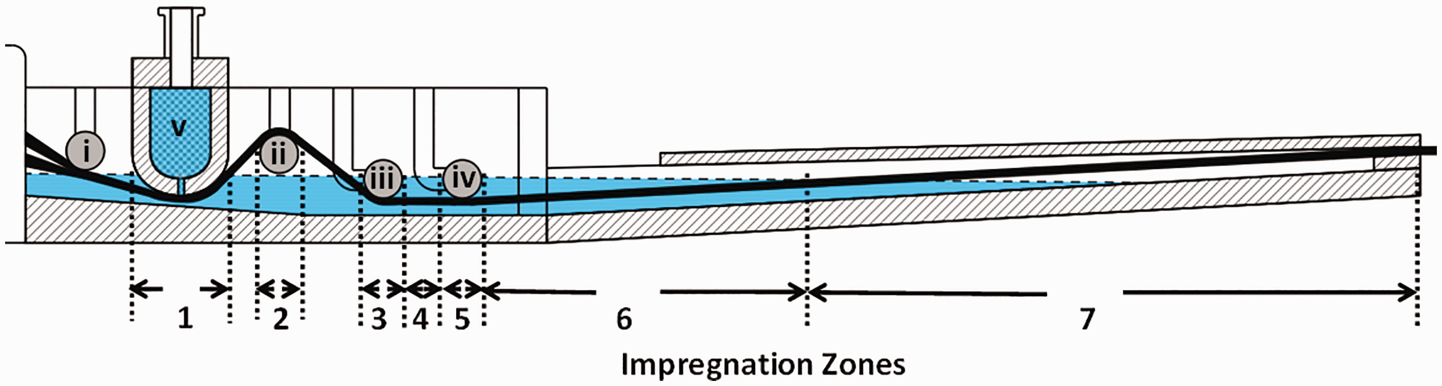
Schematic illustration of the impregnator showing generalised impregnation modes at specified regions.
Design calculations for the impregnation unit
The theoretical basis for the design of the impregnator unit, including an assessment of the different modes of impregnation as a function of specified processing parameters, was detailed in reference. 32 Hence, only a summary is presented here. The modes of impregnation at the zones indicated in Figure 3 are summarised in Table 1 along with the relevant equations that were used to calculate the degree of impregnation. 32
A summary of the relevant modes of impregnation for impregnator shown in Figure 3.
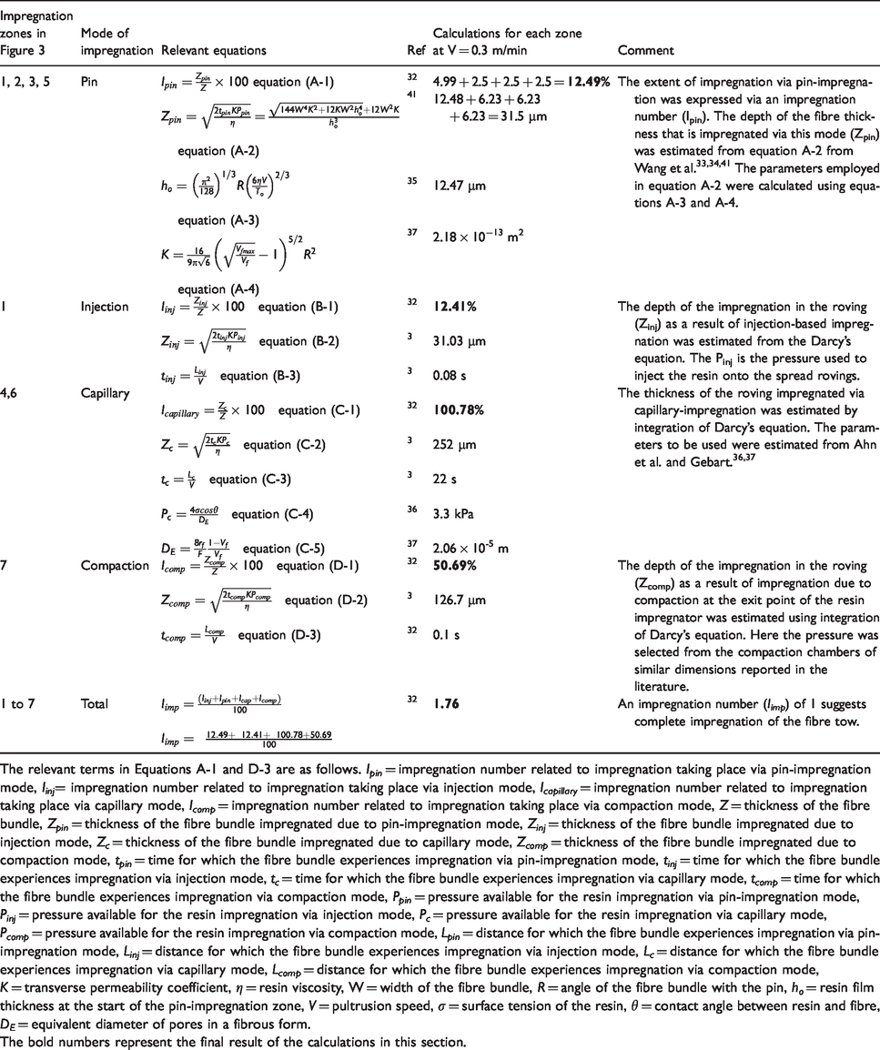
The relevant terms in Equations A-1 and D-3 are as follows. Ipin = impregnation number related to impregnation taking place via pin-impregnation mode, Iinj= impregnation number related to impregnation taking place via injection mode, Icapillary = impregnation number related to impregnation taking place via capillary mode, Icomp = impregnation number related to impregnation taking place via compaction mode, Z = thickness of the fibre bundle, Zpin = thickness of the fibre bundle impregnated due to pin-impregnation mode, Zinj = thickness of the fibre bundle impregnated due to injection mode, Zc = thickness of the fibre bundle impregnated due to capillary mode, Zcomp = thickness of the fibre bundle impregnated due to compaction mode, tpin = time for which the fibre bundle experiences impregnation via pin-impregnation mode, tinj = time for which the fibre bundle experiences impregnation via injection mode, tc = time for which the fibre bundle experiences impregnation via capillary mode, tcomp = time for which the fibre bundle experiences impregnation via compaction mode, Ppin = pressure available for the resin impregnation via pin-impregnation mode, Pinj = pressure available for the resin impregnation via injection mode, Pc = pressure available for the resin impregnation via capillary mode, Pcomp = pressure available for the resin impregnation via compaction mode, Lpin = distance for which the fibre bundle experiences impregnation via pin-impregnation mode, Linj = distance for which the fibre bundle experiences impregnation via injection mode, Lc = distance for which the fibre bundle experiences impregnation via capillary mode, Lcomp = distance for which the fibre bundle experiences impregnation via compaction mode, K = transverse permeability coefficient, η = resin viscosity, W = width of the fibre bundle, R = angle of the fibre bundle with the pin, ho = resin film thickness at the start of the pin-impregnation zone, V = pultrusion speed, σ = surface tension of the resin, θ = contact angle between resin and fibre, DE = equivalent diameter of pores in a fibrous form.The bold numbers represent the final result of the calculations in this section.
The degree of impregnation (Iimp) was determined using the following relationship:

Iinj = impregnation via injection pressure;
Ipin = pin-base impregnation;
Icap = capillary impregnation; and
Icomp = compaction-based impregnation.
In Figure 4, the histogram shows the individual contribution of specific modes of impregnation (capillary, compaction, pin, injection and the total (a sum of the four modes of impregnation considered)). The scatter-plot above the histogram represents the observed trend for the total modes of impregnation. The values above “1” (unity) imply that the fibre bundles are over-impregnated. It can be seen from Figure 4 that the degree of impregnation for the impregnator designed in this study (shown in Figure 3) is greater than unity for the three pultrusion speeds considered. This implies that complete impregnation of the fibres should take place at the pultrusion speeds considered. A decreasing trend for the degree of impregnation with an increase in the pultrusion speed is apparent. The data required for estimating the degree of impregnation Iimp are summarised in Tables 2 and 3.
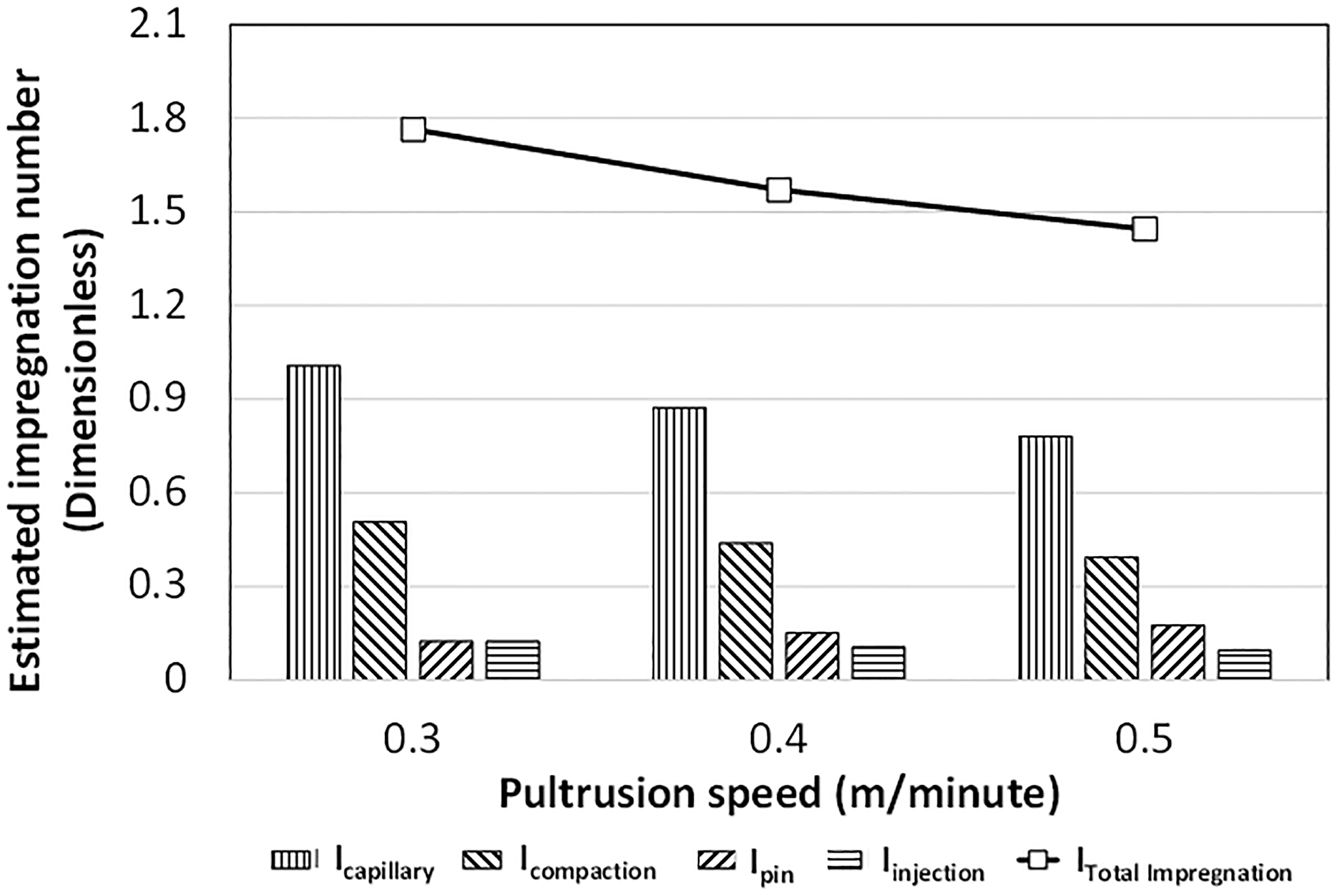
Simulation of the degree of impregnation as a function of the pultrusion speed.
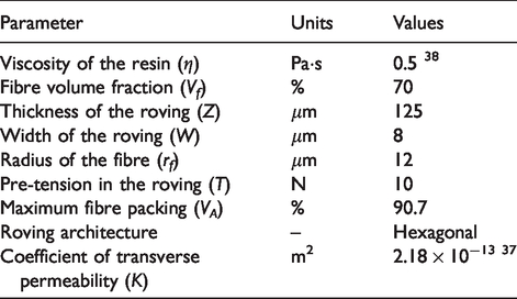
Summary of the parameters that were used to calculate the extent of impregnation.
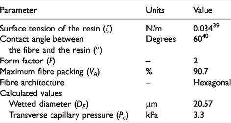
Summary of the parameters that were used to calculate the impregnation-zone length assuming capillary-impregnation.
Materials, selection of pultrusion parameters and test methods
Resin and fibres
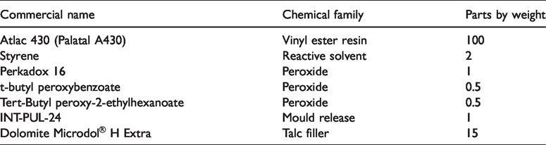
The details of the vinyl ester resin formulation used in the pultrusion experiments are presented in Table 4. The E-glass fibres (386 Direct Roving, 4800 tex) with an average fibre diameter of 24 μm were used in this study.
Details of the filled and un-filled vinyl ester resin systems used in this study.
Selection of the die-temperature and pultrusion speeds
A power-compensated differential scanning calorimeter (Diamond DSC, Perkin Elmer, UK) was used to study the cross-linking behaviour of the resin system. This was required to enable the selection of suitable temperatures for the die and to define the pultrusion speeds. The procedures reported in reference 42 were adopted. The conversion-temperature curve for the unfilled vinyl ester resin is shown in Figure 5. It can be seen from Figure 5 that at 140°C, the conversion of the reaction is nearly 90% complete. Hence, this temperature was selected as the die-temperature.
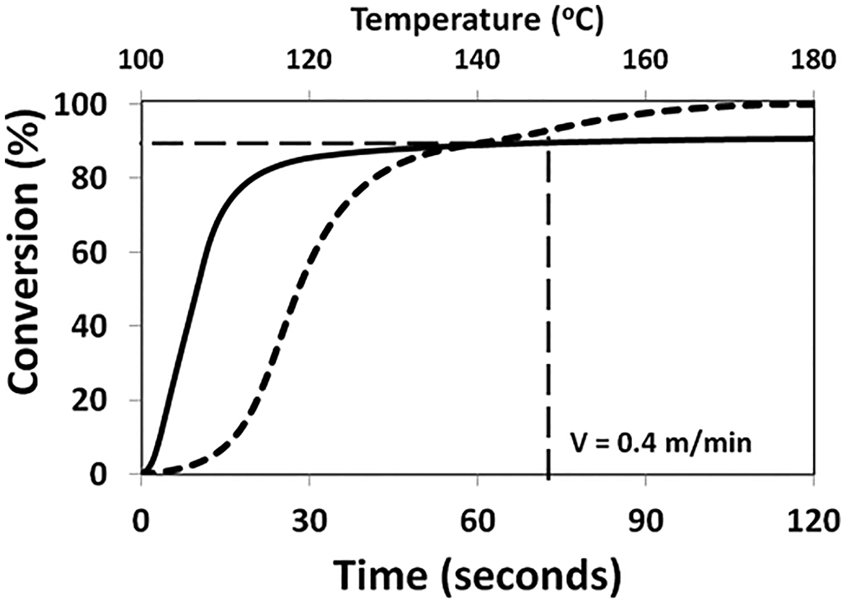
Combined plots show: (i) conversion versus temperature curve for the unfilled vinyl ester resin. The conversion curve was generated from a dynamic DSC experiment conducted at 5 K/minute; and (ii) degree of conversion at 140°C for vinyl ester resin obtained via an isothermal DSC experiment. The corresponding residence time of the fibre bundles in the die for a pultrusion speed of 0.4 m/minute used in this study is also indicated.
In the second set of experiments, the resin system was cross-linked isothermally at 140°C. The objective of this experiment was to establish the pultrusion speed which would ensure the complete cross-linking of the resin within the 0.5 m long die. From an isothermal experiment that was conducted at 140°C, a conversion curve as a function of time was generated as shown in Figure 5. A pultrusion speed of 0.4 m minute−1 was chosen for the experiments because the degree of conversion at 75-seconds (corresponding to a pultrusion speed of 0.4 m minute−1) for the 0.5 m die was approximately 90%. The average glass transition temperature (Tg) from three experiments for the unfilled vinyl ester resin was 117.9 ± 1.8°C. The Tg was measured at the mid-point of the change in the heat capacity trace in accordance with ASTM E1356-08. 43 The heating rate used for the dynamic heating experiments in the DSC was 5 K/minute.
Pultrusion experiments
The pultrusion machine used in the industrial trial was designed and built by Pultrex Ltd (Model PX500-6T) with a maximum pulling force of 6,000 kg for each of the two grippers. It was equipped with reciprocating pullers and a programmable automatic cutting device. The cross-section of the die profile used in this study was 32 mm × 2.2 mm. The conventional pultrusion experiments were performed with a dip-type resin bath with a capacity of five litres. The details of the resin systems, fibre reinforcements, die temperatures and pultrusion speeds are provided in Table 5. At the end of the pultrusion experiments, the resin that remained in the bath was transferred into small containers and cross-linked prior to disposal. The components that came into contact with the mixed resin (resin bath, profile guides, plunger and feed-back tray) were removed at the end of the trial and cleaned using acetone. The resin impregnator, designated as “PUL-I” was used for the modified pultrusion experiments. The resin system was premixed and transferred to a two-litre pressure-pot that was operated using compressed air. The details of the pultrusion experiments using the modified technique are provided in Table 5.
Detail of the conventional resin bath and modified pultrusion experiments.
Test methods
Density, fibre and void volume fraction: The densities of the pultruded composites were determined using an OHAUS density measurement kit (Model: AP110S). The fibre volume fraction of the pultruded samples was determined by the ignition-loss method in accordance with ASTM D 2584-08. 44 The void fraction (Vv) was determined in accordance with ASTM D 2734-16. 45 The total number of specimens used was 20.
Image analysis: The void fractions of the composites were calculated from micrographs using ImageJ image analysis processing software. 46 Standard metallographic techniques were used for potting and polishing the samples for subsequent inspection using an optical microscope (Zeiss Axioskop 2).
Thermo-mechanical properties: A dynamic mechanical analyser (DMA 242 C, NETZSCH) was used to obtain the thermo-mechanical properties of the neat resin system and the pultruded composites. Each sample was clamped in the machine using a dual-cantilever fixture and heated from 25°C to 180°C at 3 K minute−1. The experiments were conducted at 1 Hz. A minimum of three samples were tested for each of the specimen types.
Inter-laminar shear and flexural properties: The inter-laminar shear strength (ILSS) of the pultruded composites was measured in accordance with BS EN ISO 14130:1998 and the flexural strength and modulus of the composites were measured in compliance with ASTM D 6272-08. Five samples each were used for the ILSS and flexural tests.
Results and discussion
Site trial
The advantages and the future potential of the modified pultrusion method over the conventional resin bath-based technique observed during the site trial were as follows.
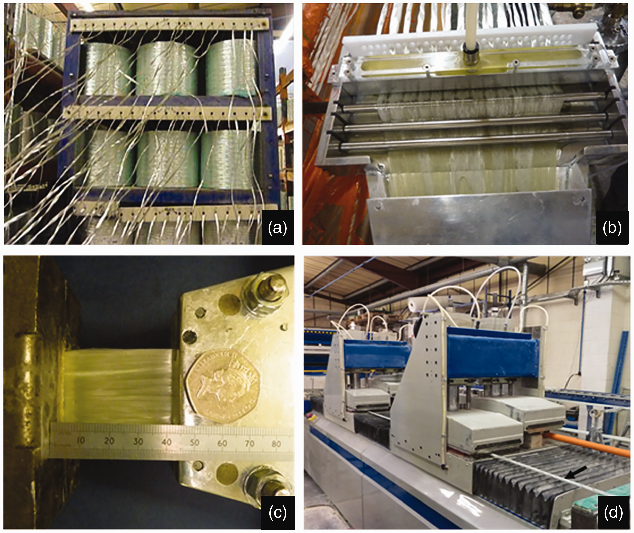
Ease of retrofitting: The retrofitting of the impregnation unit was relatively straightforward as it involved securing the impregnation unit on the top of the empty resin bath. It did not require any modification to the original equipment. A photograph of the experimental setup that was used on site is shown in Figure 6(a) to (d): (a) illustrates the fibre creels on a creel stand; (b) shows the resin impregnation unit; (c) illustrates the impregnated fibre bundles from the impregnation unit entering the die; and (d) shows the haul-off unit. The rectangular strip (indicated by the arrow) in Figure 6(d) represents the composite made using the modified pultrusion process.
Photographs showing the on-site pultrusion trials: (a) Fibre creel and stand; (b) impregnator; (c) impregnated fibre bundles entering the heated die; and (d) haul-off unit (the sample in the front represents the composite that was manufactured using the modified pultrusion technique. Control over the extent of impregnation and pot-life of the resin: In the modified pultrusion method, the required volume of resin is delivered to the partially spread fibres in a consistent basis. During conventional pultrusion, it was observed that the fibres emanating from the resin bath were over impregnated. A significant volume of the excess resin was squeezed out from the bundles at the pre-die guides and they were directed back to the resin bath via the drip tray. The dimensions of the pre-die guides are engineered to remove the majority of the excess resin from the fibre bundles because at the entry point to the die, the excess resin that is expelled back to the resin bath is heated to some extent by the die. This can have implications to the pot-life of the resin and its viscosity in the resin bath. The effect of some of the processing parameters on the pultrusion speed was reported previously by the authors.
32
A detailed study on the effect of process variables (viscosity, applied injection pressure, tow thickness and haul-off rate) on impregnation was reported previously for filament winding.
3
Non-unidirectional reinforcements and complex die profiles: In order to undertake a comparative study between the conventional resin bath and modified pultrusion techniques, a rectangular strip die geometry was chosen as it permitted the standard range of properties to be evaluated as outlined in Synchronising the pultrusion speed to the resin delivery rate: A notable advantage of the modified pultrusion technique is that the resin dispensing unit is synchronised to the pultrusion speed. Therefore, as the pultrusion speed is increased, the resin delivery rate can be increased in proportion. There is potential to increase the pultrusion speed further in the modified method but it will need ancillary equipment to enable a higher degree of fibre spreading.
2
Solvent usage and the time required for cleaning: The time required to clean the resin bath and the resin impregnation units were 20 and 8 minutes respectively. The volume of solvent that was required to clean the conventional resin bath was ∼2000 cc where as that for the resin impregnator was ∼200 cc. Fast curable resins: There is also scope to introduce fast-curing resins using the modified pultrusion technique.
As with any modification to an established commercially relevant manufacturing method, it was necessary to demonstrate that the relevant properties of the pultruded composite were not compromised. In the current study, the fibre and void volume fractions were used in conjunction with the density, mechanical and thermo-mechanical properties as indicators of the quality of the composites manufactured via the conventional and modified methods. The retention of fibre orientation (as opposed to meandering) and the extent of compaction were assessed via image analysis.
Fibre volume and void fractions and density
Fibre volume fraction and density: The fibre volume fractions and densities for the unfilled and filled vinyl ester/E-glass composites are shown in Figure 7. In the case of the unfilled resin system, the fibre volume fractions and the densities for the conventional and modified pultruded composites are similar. When the unfilled resin was used, it was possible to feed twenty eight rovings of 4800 tex E-glass into the die. However, only twenty-four rovings were used with the filled resin system. The number of fibres for the filled-resin was reduced as it was not possible to add more than twenty-four rovings into the die. The conventional and modified techniques show similar values for the fibre volume fractions and density.
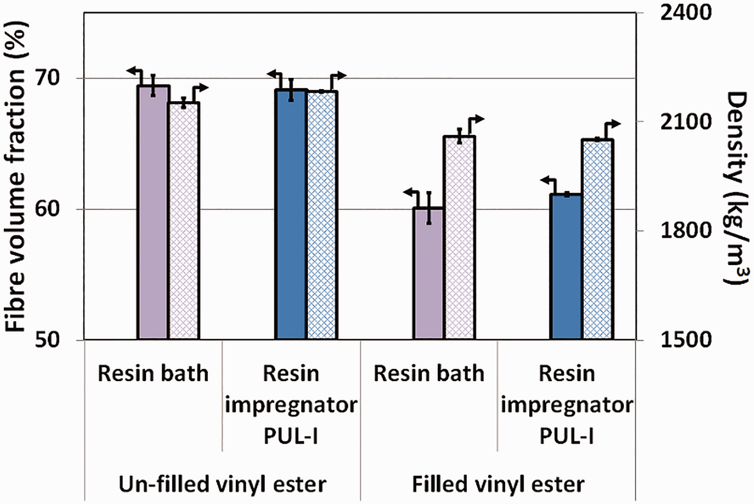
Fibre volume fraction and density for the pultruded vinyl ester/E-glass composites produced on-site at 0.4 m/minute.
Void Fraction: With reference to the unfilled vinyl ester resin system (see Figure 8), the average void fractions for the composites produced via the conventional and modified pultrusion processes were 1.40 ± 0.29% and 0.27 ± 0.25% respectively. The average void fraction for the filled resin system for the conventional and modified pultrusion methods were 0.45 ± 0.53% and 0.64 ± 0.78% respectively. However, significant scatter is observed in all the data sets. Possible reasons for the relatively large scatter may be due to: (i) the variability in the binder content in the E-glass fibre bundles; (ii) the fibre spreading unit breaking up areas of excess binder that could have been present on the bundles; or (iii) the homogeneity of the filler in the composite. A detailed study on this subject will be presented in a subsequent publication. Experimentally derived numerical data for the densities, fibre volume and void fractions for the two manufacturing techniques, with and without the filler are provided in Table 6.
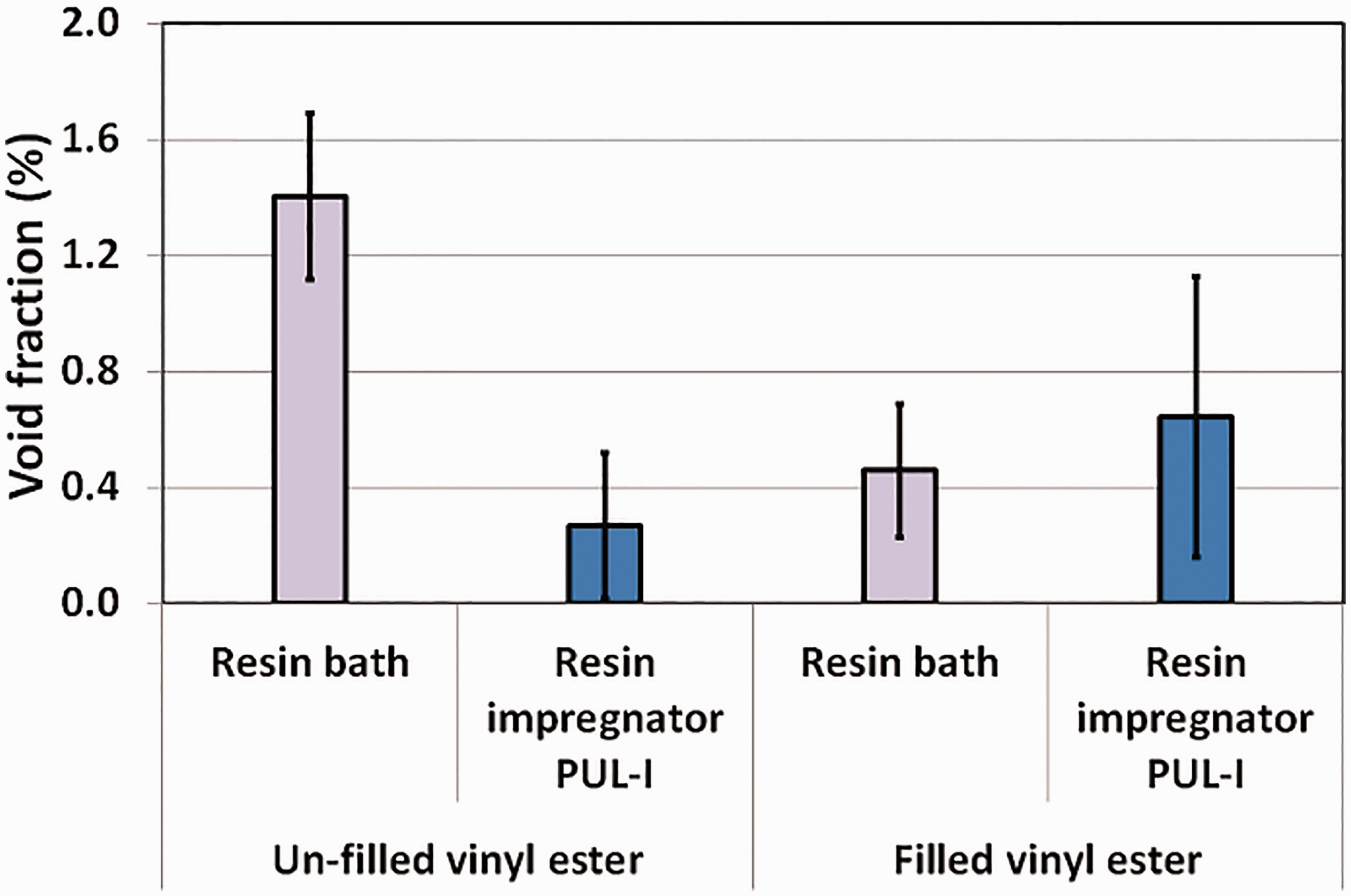
Void fraction data for the unfilled and filled vinyl ester/E-glass pultruded composites produced on-site at 0.4 m/minute. The void fractions were determined in accordance with ASTM D 2584-08.
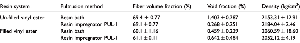
Experimentally derived data for the fibre volume fraction, void fraction and densities of pultruded composites using the conventional and modified pultrusion techniques; with and without the filler.
Representative micrographs of the conventional and modified pultrusion methods, with and without the filler, are shown in Figure 9. On inspecting Figure 9(a) and (b) (resin bath and unfilled resin) with Figure 9(c) and (d) (PUL-1 and unfilled resin), extent of fibre compaction is seen to be marginally higher for the modified pultrusion method. A notable feature in these samples was the significantly lower void content. Figure 9(e) to (h) represents that samples that were produced with the filled resin system using a conventional resin bath and PUL-I respectively. The observed degree of fibre compaction for the filled resin system is seen to be comparatively lower and this is assumed to be a consequence of the presence of the filler. The unfilled vinyl ester resin system shows higher shrinkage when compared to the matrix with the filler.48–50 A magnified image of de-bonding caused by the compact fibre architecture and resin-shrinkage in the unfilled vinyl ester resin system is shown in Figure 10. The effect of the higher void fraction in the unfilled composites is manifested by the lower mechanical properties (flexural and inter-laminar shear strengths).
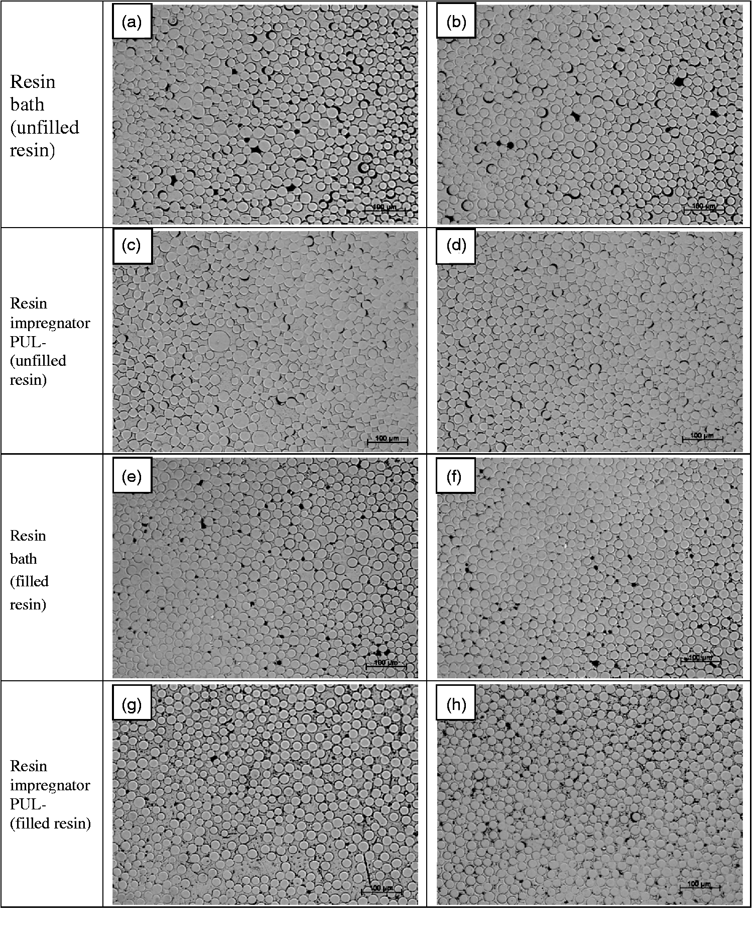
Micrographs of unfilled and filled vinyl ester/E-glass pultruded samples: (a) resin bath using unfilled resin (low-void sample); (b) resin bath using unfilled resin (high-void sample); (c) impregnator PUL-I using unfilled resin (low-void sample); (d) impregnator PUL-I using unfilled resin (high-void sample); (e) resin bath using filled resin (low-void sample); (f) resin bath using filled resin (high-void sample); (g) impregnator PUL-I using filled resin (low-void sample); and (h) impregnator PUL-I using filled resin (high-void sample).
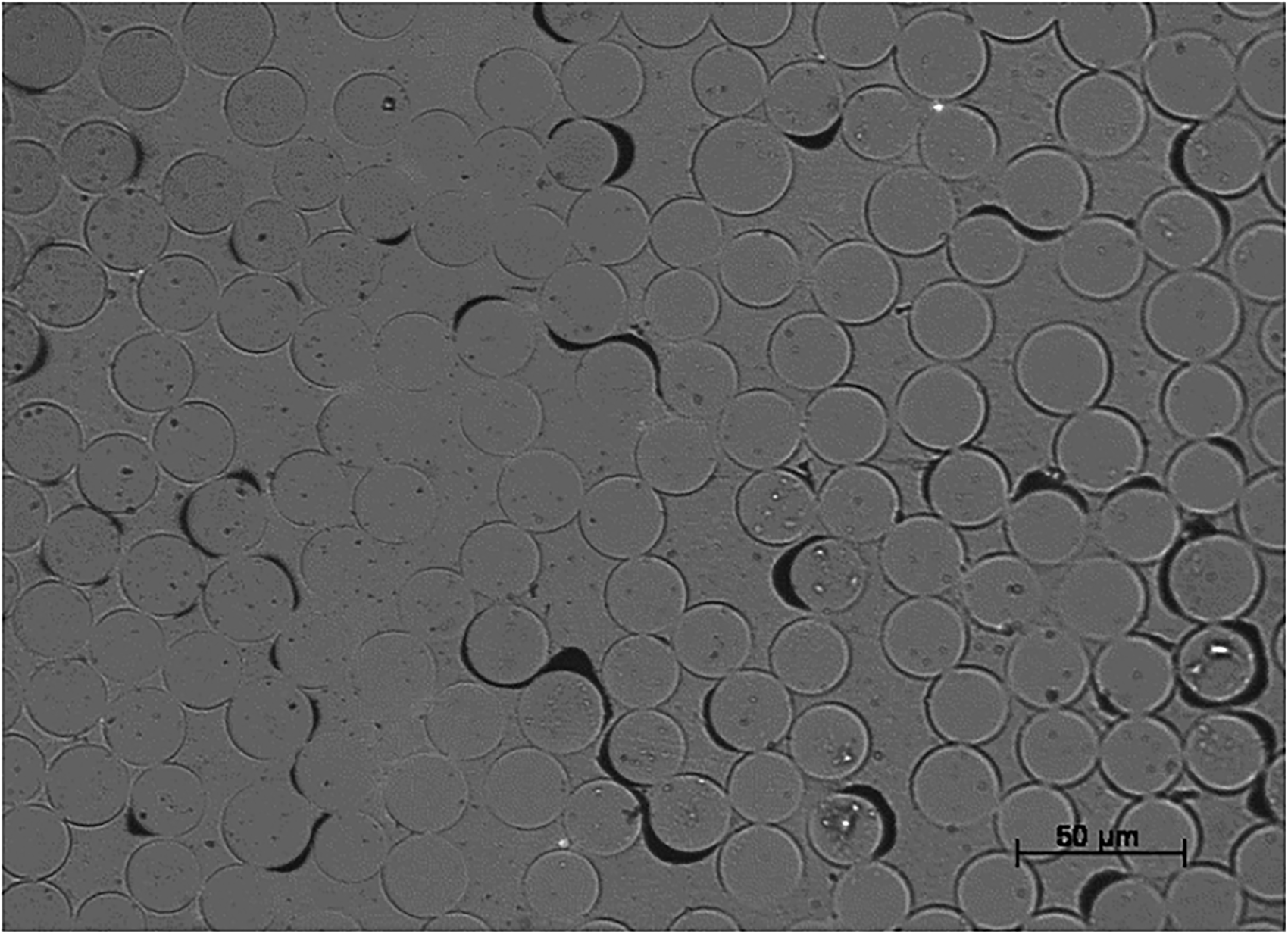
Micrograph of an unfilled vinyl ester/E-glass sample showing the de-bonding of the resin from the fibres caused by resin shrinkage.
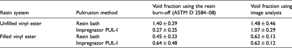
A comparison of the void fraction data, determined using the resin burn-off and image analysis methods, is presented in Table 7. With the exception of the modified pultrusion method using the unfilled resin system, a good correlation is observed between the two methods.
Comparison of the void fraction data for the pultruded vinyl ester/E-glass composites obtained by image analysis and the resin-burn off method.
Flexural and inter-laminar shear properties, and dynamic mechanical thermal analysis
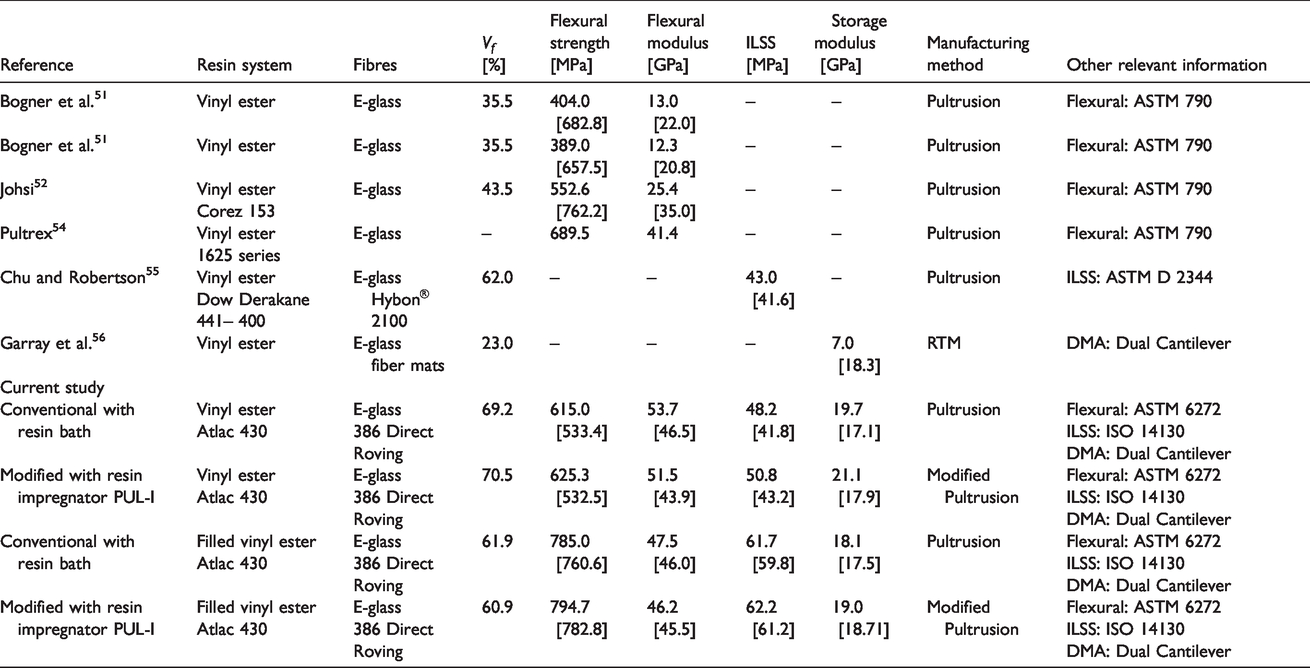
Flexural properties: Figure 11(a) and (b) shows the flexural strengths and flexural moduli respectively for the modified and conventional pultrusion techniques for the unfilled and filled vinyl ester/E-glass composites. The term “normalised” represents the case where the flexural strength and modulus were normalised to 60% fibre volume fraction; the average fibre volume fraction which was used for each class of pultruded composite. It can be seen that there is no significant difference between the flexural strengths of the composites produced by the conventional and modified techniques. The flexural properties are lower for the unfilled systems which may be due to de-bonding at the fibre-matrix interface as seen in Figure 10. A T-test was undertaken to compare the normalised pairs of data and it was found that the data pairs are statistically insignificant for the conventional and modified pultrusion methods. On comparing the flexural strengths of the composites produced in this study with those reported in the literature,51–53 it can be seen from Table 8 that the data for the filled composites are similar or higher than those reported by other researchers. On the other hand, the unfilled composites exhibit lower flexural strengths. This may be related to the presence of extensive de-bonding as discussed previously.
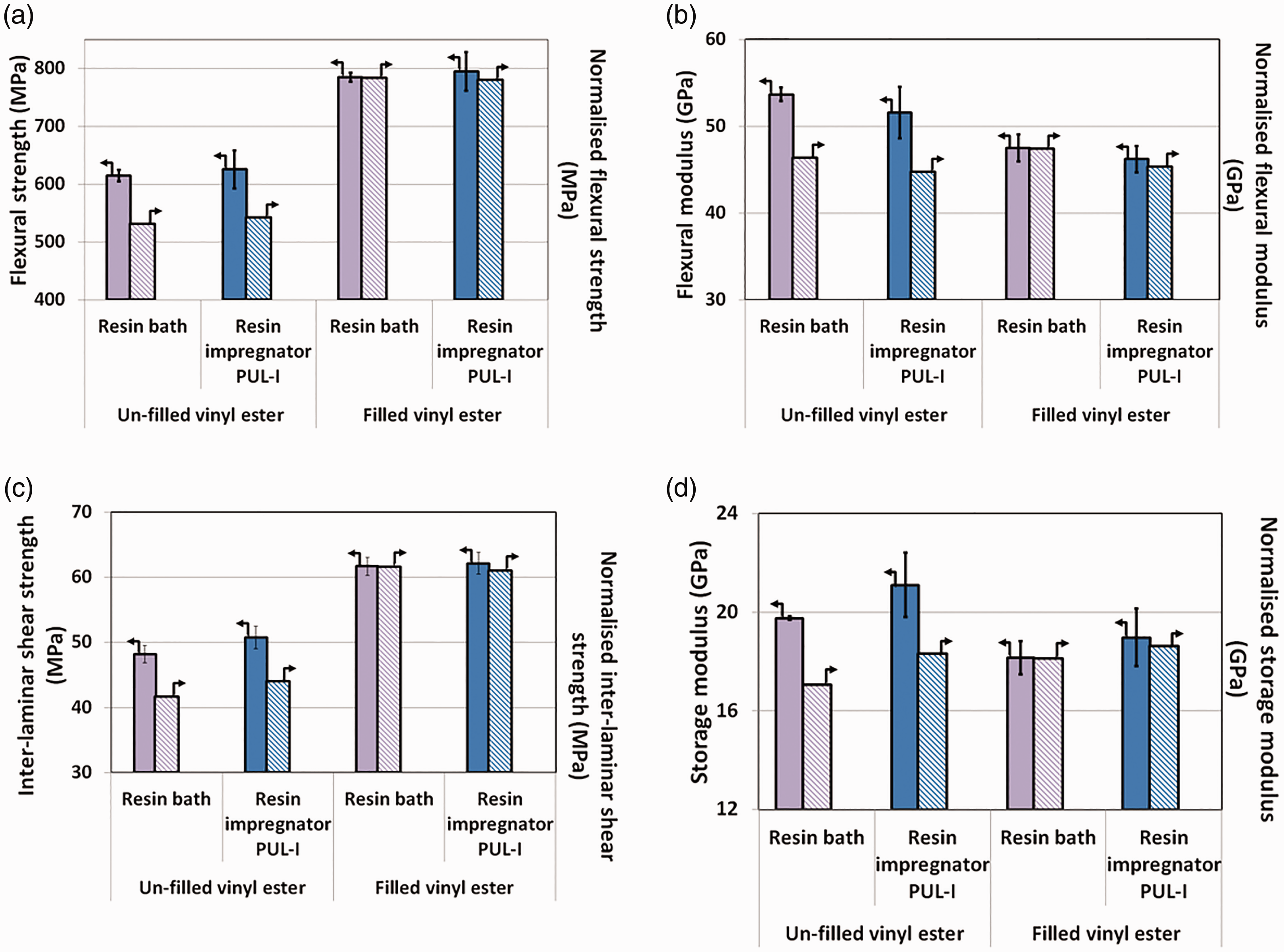
Mechanical and thermo-mechanical properties of the pultruded vinyl ester/E-glass composites produced at 0.4 m/minute. (a) Flexural strength. (b) Flexural moduli. (c) Inter-laminar shear strength. (d) Storage moduli.
Summary of selected papers to enable a comparison of the properties of the UD E-glass composites. The data in square brackets represents normalised fibre volume fraction at 60%.
Inter-laminar shear strength: The inter-laminar shear strengths (ILSS) for the pultruded composites are presented in Figure 11(c). As observed with the flexural strength data, the ILSS data for the composites pultruded using the conventional and modified techniques are similar for the unfilled composites. In the case of the filled composites, the ILSS values are similar for the conventional and modified techniques; however, these are higher than that observed for the unfilled composites. This is in agreement with published data. 54
Dynamic mechanical thermal analysis: As observed previously for the flexural moduli, the storage moduli (E’) for the unfilled and filled resin systems are similar for the composites (normalised fibre volume fraction data) produced via conventional and modified pultrusion techniques – see Figure 11(d). The importance of normalising the mechanical properties, using the respective fibre volume fractions, to a common reference value (60% in the current case) is apparent in Figure 11 and Table 8. This approach also enables the data presented here to be compared with that reported in the literature.
Solvent usage and cleaning time
A key feature of the impregnator design was the multiple modes of impregnation of the partially spread fibre bundles (see Table 1 and Figure 3). This meant that the effective lengths of impregnation zones could be minimised to achieve full impregnation of the fibre bundles. Furthermore, the “dead volume” in the impregnator was approximately 100 cm3. The overall volume occupied by the resin during production was 965 cm3. The net effect of these factors was: (i) the volume of the resin that was retained in the impregnator at the end of a production cycle was 100 cm3; and (ii) the volume of solvent required to clean the impregnator was 200 cm3. A direct comparison with the conventional resin bath-based pultrusion process is not disclosed here due to industrial confidentiality. However, Figure 12 shows the outcome of a laboratory-based study where the conventional and modified pultrusion processes were subjected to a life cycle assessment using a commercially available LCA package. The primary benefit of the modified pultrusion technique is the significant reduction in the generation of waste resin and the lower volume of solvent required to clean the impregnator at the end of a production cycle.
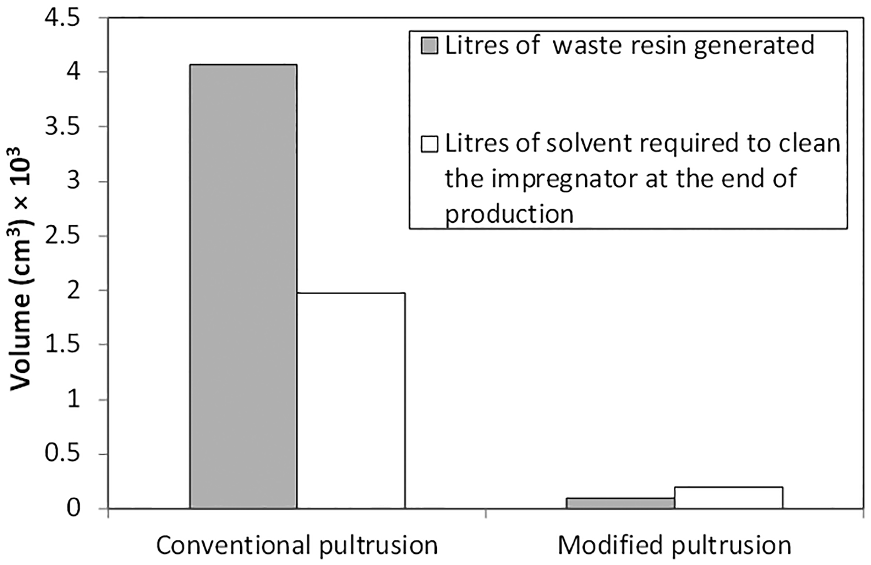
Volume of solvent required for cleaning and the volume of waste resin generated for the conventional and modified pultrusion methods using experimental data generated in the laboratory using E-glass fibres and vinyl ester resin.
Unlike conventional pultrusion where the excess resin that drips from the entrance to the hot-die is channelled back to the resin bath, in the modified pultrusion process, this volume is reduced significantly. Hence, it can be assumed that the pot-life of the resin contained within the impregnator is likely to be longer. The physical and mechanical properties obtained using the modified pultrusion technique were found to be marginally superior or equivalent to that obtained using the conventional resin bath-based method. Thus, it can be concluded that the modified pultrusion technique does not lead to any reduction in the above-mentioned properties.
The main advantages of the modified pultrusion process are: (i) a 97% reduction in the generation of waste resin; and (ii) a 90% lower solvent consumption for cleaning the equipment at the end of each production shift. The cost of the implementation of the modified pultrusion technique is dictated by the choice of the resin delivery system. The cost of a pressure-pot based system will be significantly lower but it will require the resin and hardener to be weighed and mixed manually. An automated pumping system will be more expensive but it can enable the use of resin systems with a higher reactivity and shorter pot-life. Moreover, the long-term benefits accrued from lower solvent consumption and significantly reduced cleaning time at the end of each production cycle need to be considered. The impregnator (Figures 2 and 3) can be modular and additional features such as pins, rollers, injectors, etc can be included as required.
Conclusions
A modified pultrusion process was evaluated in an industrial environment to pultrude vinyl ester/E-glass fibres using filled and unfilled resin formulations. The custom-designed impregnator was retrofitted to the pultrusion line by securing it on the top of the empty resin bath. The impregnator design used in this study was capable of handling filled resins. In this production method, the fibre bundles were partially spread via a fibre spreading rig prior to impregnation to enhance the through-thickness impregnation. Thermal analysis was used to obtain the die temperature profile and the pultrusion speeds. The physical, mechanical and thermo-mechanical properties of the pultruded composites produced, using the conventional and modified techniques, were compared. It was shown that the composites produced using the modified pultrusion technique had similar or marginally superior properties when compared to those produced using the conventional resin bath-based method. In the context of the green credentials of the modified pultrusion technique, when compared to the conventional five litre resin bath, it was demonstrated in an industrial setting that: (i) the volume of solvent required for cleaning the custom-designed impregnator, at the end of each production cycle, was reduced by 90%; and (ii) the volume of resin that is retained within the impregnator was lowered by 97%.
Footnotes
Acknowledgements
The support given by the industrial partners (Pultrex, PPG, CTM and Huntsman Polyurethanes) is duly acknowledged. The authors wish to acknowledge the technical assistance provided by Professor B. Ralph, F. Biddlestone, F. N. Bogonez and L. Wang.
Declaration of Conflicting Interests
The author(s) declared no potential conflicts of interest with respect to the research, authorship, and/or publication of this article.
Funding
The author(s) disclosed receipt of the following financial support for the research, authorship, and/or publication of this article: This work was supported by Engineering and Physical Sciences Research Council (TS/G000387/1) and the Technology Strategy Board, Project AB134K and BD072K.