
Abstract
High-deposition-rate welding is used in the fabrication of liquefied natural gas tanks from thick aluminium plates because the weld defect generally increases and the productivity decreases with increasing number of passes. In this study, high-deposition-rate gas metal arc welding was implemented in vertical-up and horizontal positions. High deposition was achieved in the vertical-up position by pulse welding using 2.4-mm single wire and 1.6-mm twin wires and in the horizontal position by electromagnetic lifting of the weld pool. The arc stabilities for the applied processes were examined and welding procedures for thick plates were developed. A total of 14 welding passes were required for the vertical-up welding of a 70-mm thick plate by using the conventional 1.6-mm single-wire process, and the fully penetrated welds could be achieved with 8 welding passes by using twin-wire welding. Also, 10 welding passes were required for the horizontal welding of a 35-mm-thick plate by the conventional approach, and 6-pass full-penetration welding was successfully implemented by applying an external electromagnetic field.
Introduction
Thick Al 5083 plates are used for independent-type tanks of liquefied natural gas (LNG) carrier vessels such as self-supporting spherical-type B (spherical) tanks and self-supporting prismatic-type B (SPB) tanks. 1 The wall of the spherical LNG tank is generally thicker than that of the SPB tank,2–4 and the technology for manufacturing spherical tanks with 70-mm-thick walls for a 200,000-m3 capacity LNG carrier is being developed in Korea.
Position welding methods such as vertical and horizontal welding are essential for fabricating large-scale spherical tanks. To stabilise position welding of aluminium alloy, ‘meso-spray’ mode welding between spray and short-circuit mode welding was suggested in the late 1970s and was later industrialised in shipyards. 5 With rapid advances in welding power sources, digitally controlled pulse-welding techniques have been introduced for aluminium welding, and pulsed twin-wire welding was proposed for vertical-up welding of thick aluminium plates. 2 The authors previously investigated the characteristics of high-current welding of thick Al 5083 plates using single-wire welding and twin-wire welding in the flat position. 6 In this study, welding wires of diameters 1.6, 2.4, and 3.2 mm were used for single-wire welding, and two 1.6-mm-diameter wires were used for twin-wire welding. Twin-wire welding was effective for avoiding the formation of puckered beads, and single-wire welding exhibited better spatter suppression. The first aim of this study was the evaluation of the processes of vertical-up welding and development of welding procedures for 70-mm-thick Al 5083 plates.
In horizontal welding, the molten pool sags due to gravity, which produces weld defects such as overlap and lack of fusion. Previous studies revealed that the welding arc and weld pool could be deflected by electromagnetic force7,8 and a mechanical arc rotating system. 9 Researchers recently invented a weld pool lifting system that uses a single magnetic pole for horizontal welding of aluminium alloy. 10 The second aim of this study was the investigation of the feasibility of the newly developed weld pool lifting system for horizontal welding of thick aluminium plates.
Vertical-up welding
Experimental setup
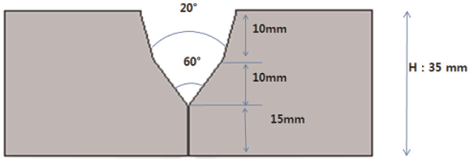
In the vertical-up experiments, an Al 5083 plate of thickness 70 mm was used as the base material, the front side groove shape of which is shown in Figure 1. The back side groove was machined as a U groove with a root radius of 5 mm, included angle of 10°, and depth of 20 mm after three welding passes on the front side. 11 The filler metal was Al 5183, and a 2.4-mm wire was used for single-wire welding and two 1.6-mm wires were used for twin-wire welding. The Fronius TPS 5000 power sources were used in this study and operated in the pulse-welding mode. In the twin-wire welding, two power sources were synchronised to generate staggered pulses from both electrodes. The contact tip-to-workpiece distance (CTWD) was set to 20 mm. A 33:67 mixture of Ar and He was used as the shielding gas and was supplied at a flow rate of 50 L/min. Angular torch weaving was employed to avoid lack of fusion on the side wall. During the multi-pass welding, the interpass temperature was maintained below 60 °C and, to enhance productivity, mechanical grinding of the bead surface between successive passes was not done. Prior to setting up the welding procedures for both types of wires, high-speed images of the root-pass and second-pass welding with a 2.4-mm-diameter single wire were captured using a frame rate of 2000 frames/s to confirm the arc stability in the narrow groove.
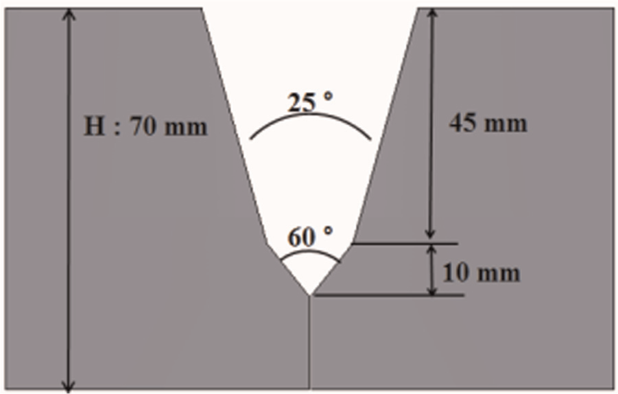
Front side groove shape for vertical-up welding: (a) root pass (welding current: 222 A; welding voltage: 25.6 V; wire feed speed: 4 m/min; welding speed: 0.2 m/min; weaving width: 4 mm; weaving frequency: 2 Hz; dwell time: 0.3 s) and (b) second pass (welding current: 240 A; welding voltage: 25.5 V; wire feed speed: 4.3 m/min; welding speed: 0.2 m/min; weaving width: 6 mm; weaving frequency: 2 Hz; dwell time: 0.6 s).
Arc movement
During V-groove weaving welding using an acute groove angle, arc aiming rapidly changes from the root to the side wall at the edge between the weld pool and the groove wall. 12 This drastic arc movement could produce weld defects such as lack of fusion at the edge. In this study, a very small groove angle was used, and the arc movement was therefore monitored by a high-speed camera. Figure 2 shows the high-speed images of the welding arc at various arc positions during the root-pass and second-pass welding. Regardless of the arc position, the arc was constantly aimed almost perpendicularly downward at the welding pool rather than at the side wall.
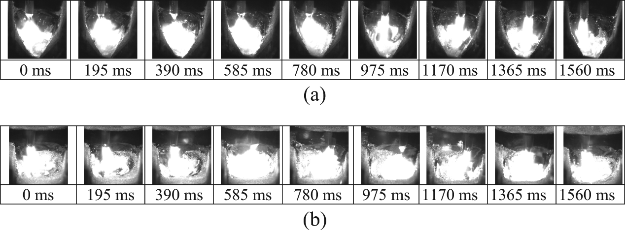
Arc shapes during narrow-groove welding.
Welding procedures
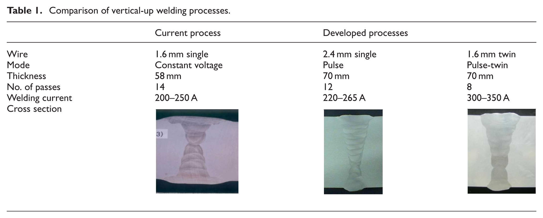
The developed welding processes for the 70-mm-thick aluminium plate employed a 2.4-mm single wire and 1.6-mm twin wires. The developed welding sequences and bead shapes are shown in Figures 3 and 4, respectively. Side bend tests for three samples per case were conducted in accordance with the Det Norske Veritas (DNV) rule, 13 and no defect was observed in the weldment by naked eye visual inspection. The conventional and developed processes are compared in Table 1. The 1.6-mm twin-wire process exhibits significantly reduced welding passes compared to the conventional 1.6-mm single-wire process. The 2.4-mm single-wire process also exhibits considerably improved productivity, stable welding arc, and spatter suppression. 6
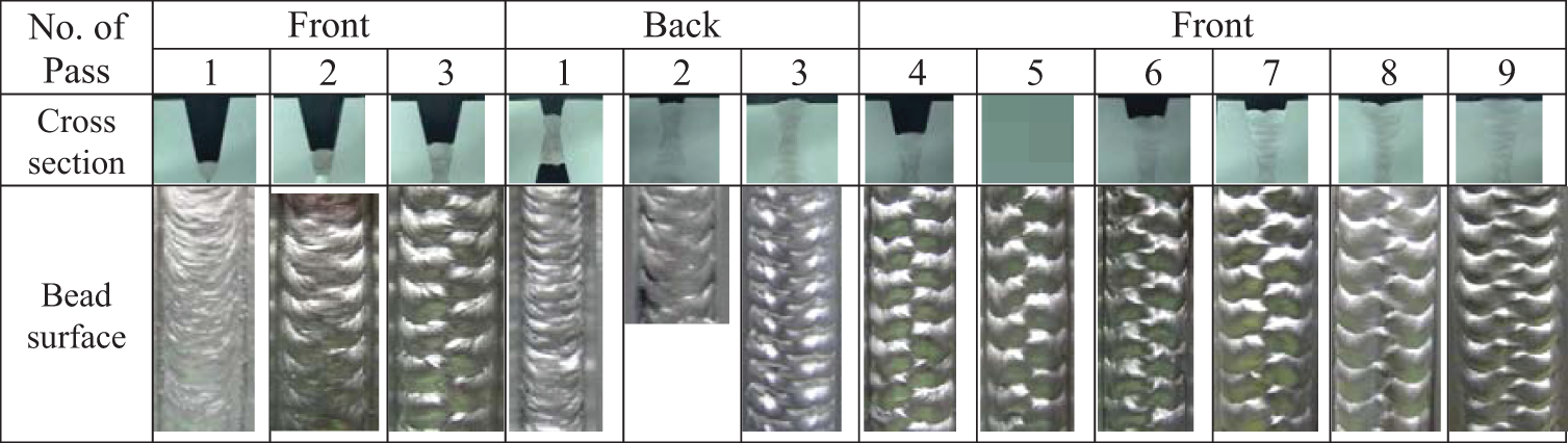
Bead shapes during vertical-up welding using a 2.4 mm single wire.
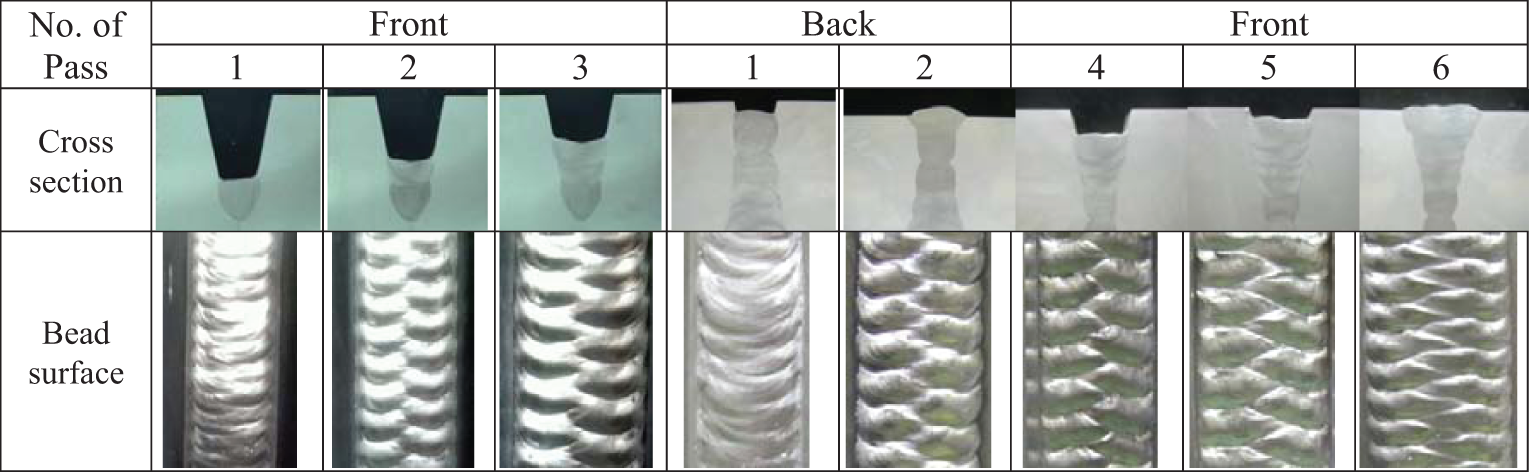
Bead shapes during vertical-up welding using twin wires.
Comparison of vertical-up welding processes.
Horizontal welding
Experimental setup
In horizontal gas metal arc (GMA) welding, the sagged weld pool obstructs direct arc heat transfer into the side wall, which could produce weld defects such as overlap and lack of fusion at the side wall as shown in Figure 5. In this study, a single-pole direct current (DC) magnetic field was externally applied to the welding arc and weld pool by an inclined electromagnet, as shown in Figure 6. The density of the magnetic field generated by a solenoid coil with a ferrite core was controlled by adjusting the current through the coil, and the magnetic flux density was measured just before the end of the electromagnet using an electromagnetic field (EMF) meter.
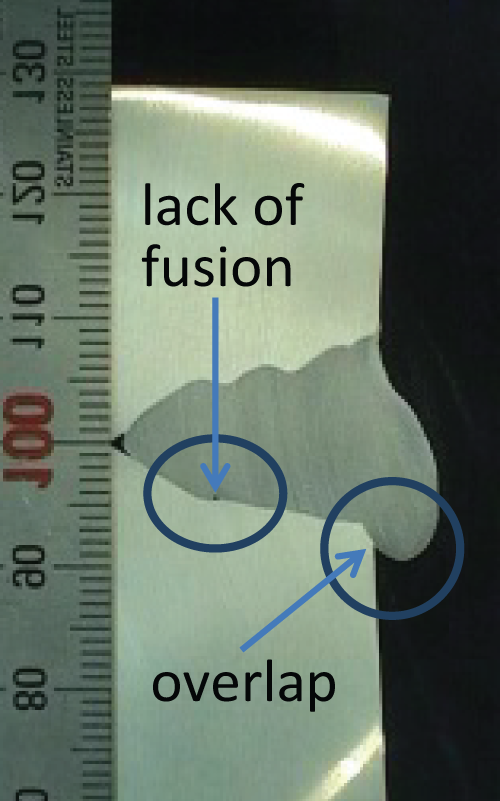
Typical weld defects of horizontal welding.
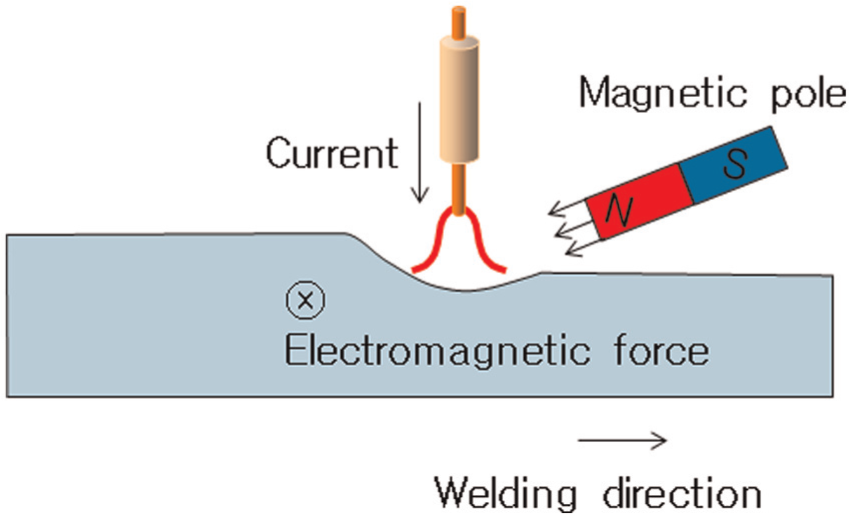
External magnetic field and resultant Lorenz force.
Prior to the horizontal V-groove welding, bead-on-plate (BOP) welding in the flat and horizontal positions were conducted on an Al 5083 plate of thickness 25 mm to investigate the feasibility of the electromagnetic deflection of the weld pool by a single-pole electromagnet. To verify the arc stability during the flat-position BOP welding, the arc current and voltage signals were recorded by an analogue-to-digital (A/D) converter, and the arc and droplet transfer was monitored by high-speed photography. The bead shapes in the flat and horizontal positions were examined for various magnetic flux densities.
Horizontal groove welding was conducted on the specimens with and without an external magnetic field. The front side groove shape is shown in Figure 7, and the back side groove shape was the same as that for the vertical-up welding.
Front side groove for horizontal welding.
Full-penetration welding was implemented on both sides, and the advantage of the weld pool lifting system that utilises an external magnetic field was investigated.
In the experiments, a 1.6-mm-diameter wire and a Fronius TPS 5000 power source was used for pulse welding. The CTWD was set to 20 mm. A 33:67 mixture of Ar and He was used as the shielding gas and was supplied at a flow rate of 20 L/min. The distance between the ends of the electrode wire and the electromagnet was 17 mm, and the angle between the torch and electromagnet was 70°.
Theoretical background
The specific gravity (ρ g) of an aluminium weld pool is 24.5 kN/m3 when 2500 kg/m3 and 9.81 m/s2 are used as the density (ρ) and gravitational acceleration (g), respectively. When a welding current of 260 A is uniformly distributed over an effective radius of 5 mm, and a uniform magnetic field density of 7.5 mT is applied, the electromagnetic force per unit volume (J B) is 24.8 kN/m3, which is of almost the same magnitude as the specific gravity.
The pool deflection by the electromagnetic flux B was calculated using a free-surface model and the energy-minimisation method. The temperature field was calculated using a quasi-steady heat conduction model and a Cartesian coordinate system moving with the heat source, as shown in Figure 8, where Φ denotes the coordinates of the free-surface profile. The details of the heat conduction model and free-surface model are available in Kim and Na, 14 Yamamoto et al., 15 and Kim et al., 16 and only the modification of the free-surface model is addressed here.
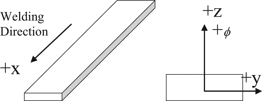
Definition of coordinate system.
When the electromagnetic force by the magnetic field in the −x direction is applied in the −y direction as shown in Figure 9, the weld pool surface can be determined by minimising the total surface energy, which includes the surface tension energy, gravitational potential energy, and total work done by the arc force and electromagnetic force.
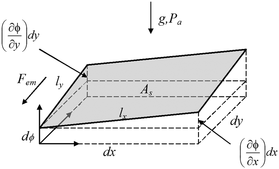
Surface deformation in weld pool.
The work done by the electromagnetic force Wm is given by
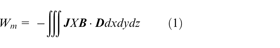
where
If the current density is assumed to be J(x,y) and only as a −z direction component, and a constant magnetic flux B is applied in the −x direction, equation (1) can be simplified as follows
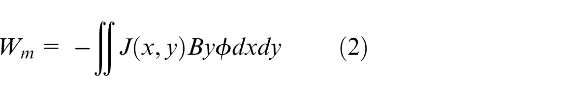
The governing equation of the free-surface model is obtained by adding equation (2) to the previous model as follows
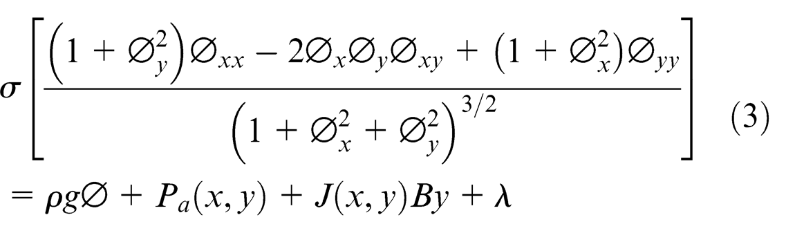
where σ is the surface tension, Pa is the arc pressure, and λ is the Lagrange multiplier.
The material properties used for the simulation were obtained from Zhao. 17 The magnetic flux B used for the simulation was 7.5 mT and the current density, J, had a Gaussian distribution parameter of 3 mm and current of 260 A. Figure 10 shows the simulated free surface produced by the electromagnetic pool deflection, which indicates that the weld pool surface could be deflected by the easily implemented magnetic flux of 7.5 mT.
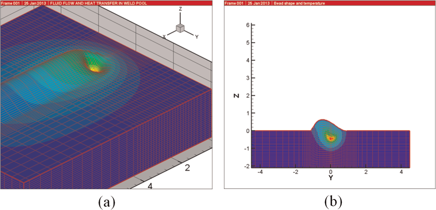
Weld pool deflection by electromagnetic force (dimensions in mm): (a) bead surface and (b) cross section.
Results and discussion
Figures 11 and 12 show the high-speed images and welding signal waveforms recorded during the BOP welding of the arc stability test. The welding arc and weld pool were deflected by the electromagnetic force, but the arc stability was not significantly affected. The welding current and voltage waveforms were almost unaffected even by applying the electromagnetic force. The welding power source controlled the welding current waveform by the preset pulsing parameters in the pulse-welding mode. The welding voltage is proportional to the CTWD in current-controlled pulse-welding mode, but the CTWD was not significantly changed in spite of deflection of the welding arc and weld pool.
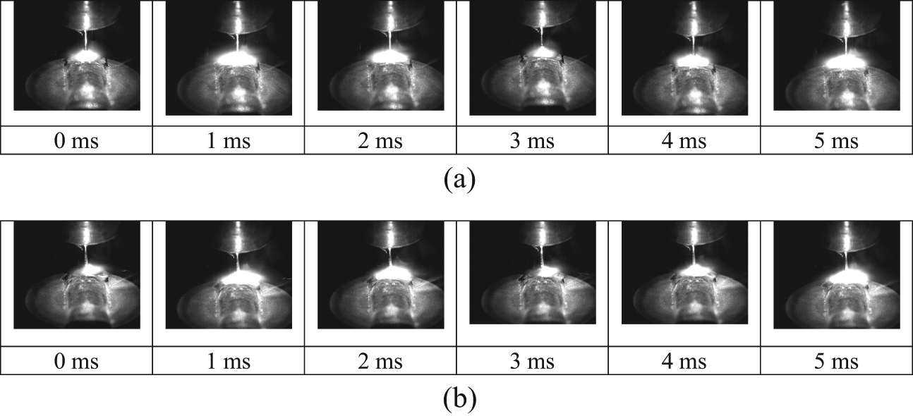
High-speed photographs taken during arc stability test (welding current: 211 A; welding voltage: 23.7 V; welding speed: 0.5 m/min): (a) without magnetic flux and (b) with magnetic flux of 70 mT.
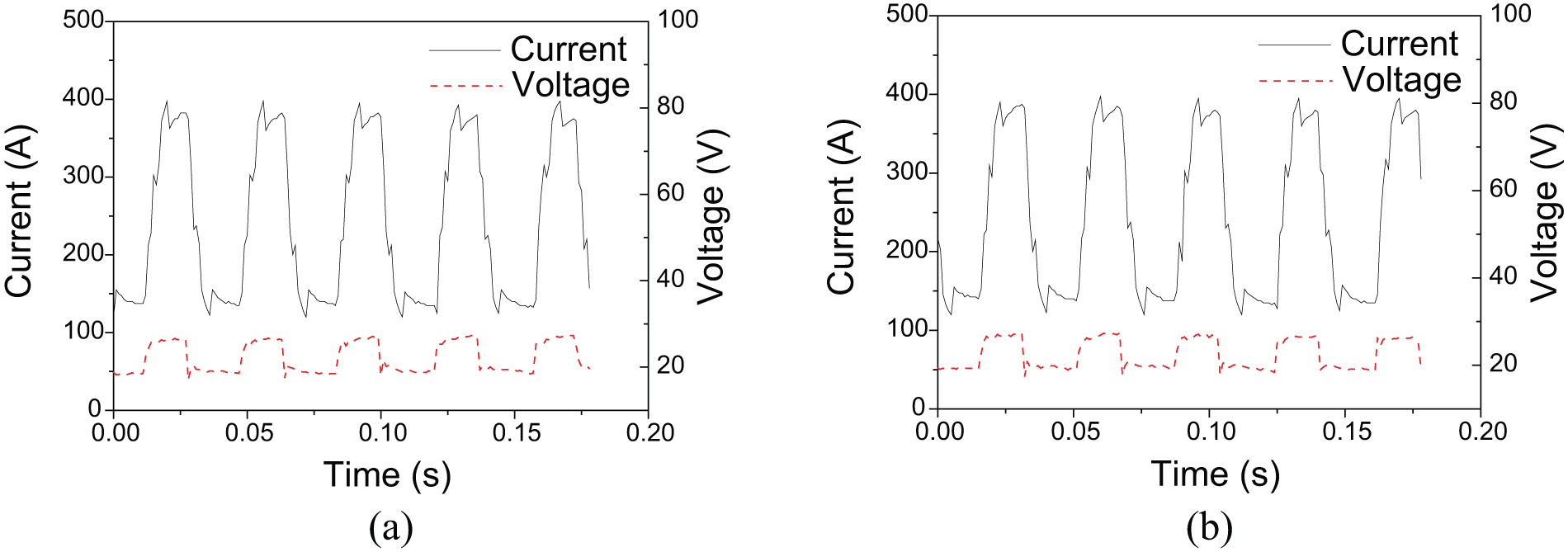
Welding signals during arc stability test (welding current: 211 A; welding voltage: 23.7 V; welding speed: 0.5 m/min): (a) without magnetic flux and (b) with magnetic flux of 70 mT.
BOP welding was conducted in the flat and horizontal positions using magnetic flux densities ranging between 0 and 55 mT. The weld pool was deflected in the direction of the electromagnetic force during flat-position welding, and even during the horizontal welding, the weld pool was lifted rather than sagged, as shown in Figure 13. The toe angle at the side against the electromagnetic force decreased with increasing magnetic flux density, and acute toe angles were achieved during horizontal welding under the EMF.
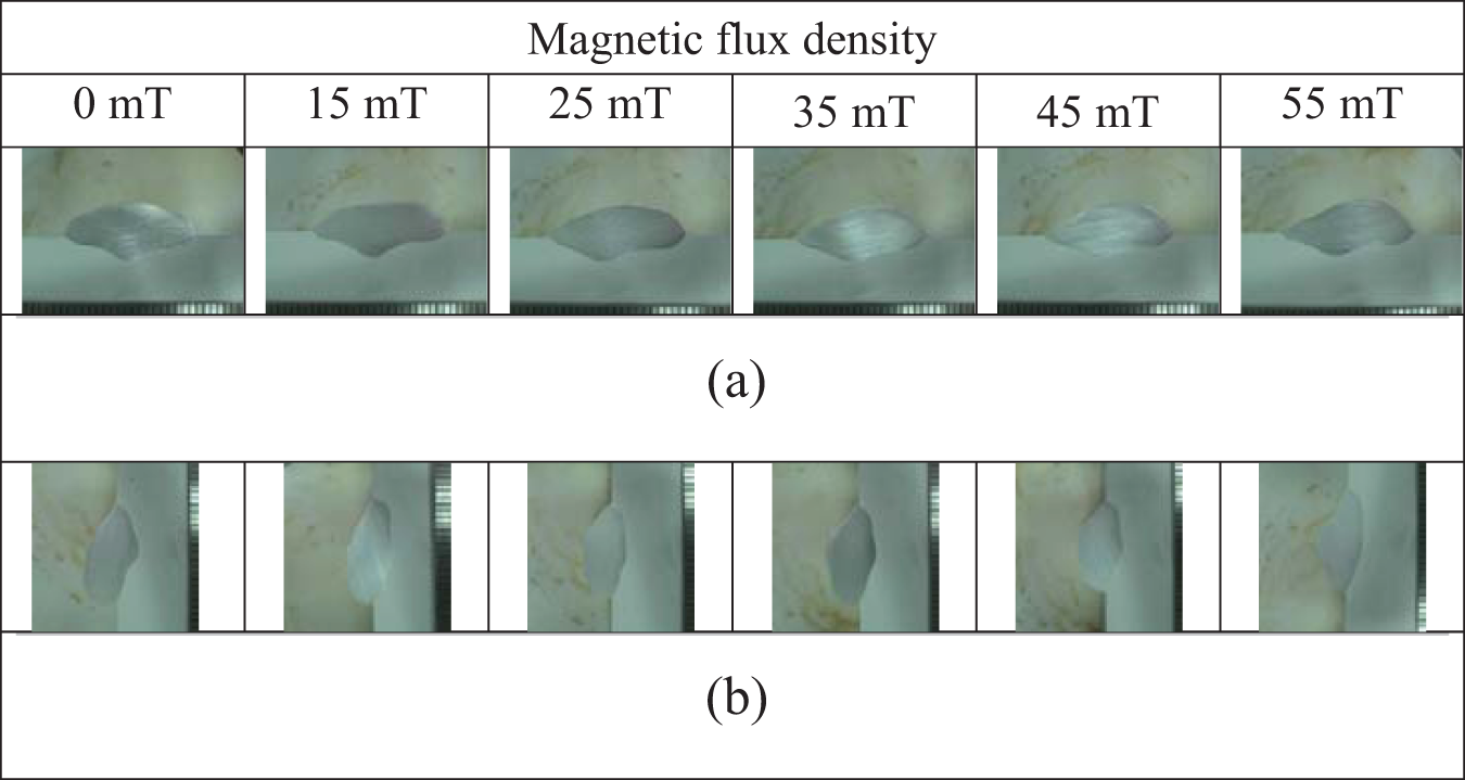
Bead shapes for various electromagnetic flux densities: (a) flat position (welding current: 211 A; welding voltage: 24.3 V; wire feed speed: 7.6 m/min; welding speed: 0.35 m/min) and (b) horizontal position (welding current: 250 A; welding voltage: 23.7 V; wire feed speed: 8.8 m/min; welding speed: 0.35 m/min).
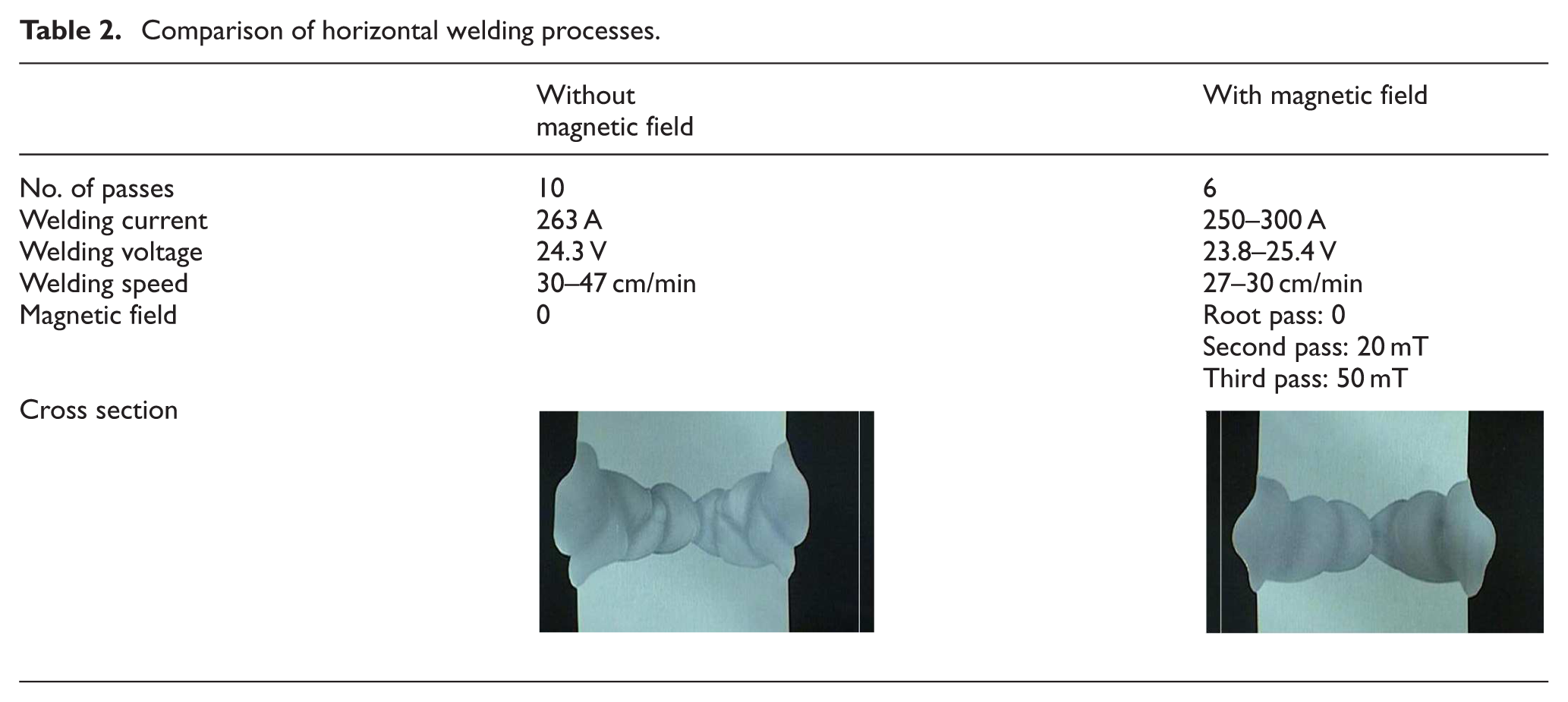
Electromagnetic pool lifting was also implemented for the horizontal-groove welding of a 35-mm-thick plate. The welding parameters and cross sections are shown in Table 2. By applying an appropriate EMF for each pass, full-penetration welds could be achieved by six welding passes on both sides, although 10 passes were required for full penetration without an EMF.
Comparison of horizontal welding processes.
Conclusion
In this study, high-deposition-rate GMA welding procedures were developed for the position welding of thick Al 5083 plates. A 2.4-mm-diameter single wire and 1.6-mm-diameter twin-wire processes were implemented for the vertical-up welding of a 70-mm-thick plate. Compared to the conventional constant voltage welding process using a 1.6-mm-diameter wire, the number of welding passes was significantly reduced and sound weld beads were produced even without interpass machining. An external magnetic field produced by a single electromagnetic pole was used to prevent the weld pool from sagging during horizontal welding. During the horizontal welding of the 35-mm-thick plate, the number of welding passes was reduced by 40% compared to welding without electromagnetic lifting.
Footnotes
Funding
This research was supported by the Ministry of Trade, Industry and Energy, Republic of Korea.