
Abstract
The recent rapid advances in digital inverter-based welding power sources have allowed the realization of pulse gas metal arc welding, which can achieve stable metal transfer even at low welding current and thus reduce heat input to the base material. Moreover, a tandem-wire process using two electrodes can dramatically increase welding productivity. In such a process, two pulse power sources are synchronized and the interference between the adjacent welding arcs is minimized. In this study, high deposition rate pulse welding for Al 5083 alloy was implemented by using Al 5183 wire of three different diameters—1.6, 2.4, and 3.2 mm. Unlike the single-wire process, tandem-wire welding was only implemented using 1.6-mm-diameter wire. The bead shape, deposition rate, process windows, and stability were evaluated for each process. The results indicate that large wire diameters and the tandem process are preferable for high deposition rates, and the penetration depth is dependent on the welding current and speed. The tandem process achieves a remarkably high deposition rate, but spatter generation at high-current levels needs to be addressed.
Keywords
Introduction
The use of natural gas is increasing because of the global regulations on CO2 emissions and the impending shortage of petroleum resources. Natural gas is liquefied at −162 °C, which reduces the volume for long-distance transport on liquefied natural gas (LNG) carrier vessels. Such commercial LNG vessels employ an independent-type “B” tank and a membrane-type tank for cryogenic storage. 1 The most important property to consider in the selection of tank materials is the low-temperature toughness, and Al alloys are the most preferred materials. Al 5083 alloy plates with a thickness of up to 200 mm can be used for spherical storage tanks, which are independent-type tanks. 2 Another proposed independent-type tank is the self-supporting prismatic-type-B (SPB) system, which can also employ the same type of Al alloy but with a relatively low thickness from 10 to 35 mm.3,4
Since the late 1970s, welding of thick aluminum plates for LNG tanks has been done with gas metal arc (GMA) welding using a large-diameter filler wire, which can achieve high deposition rates at a high welding current. This is because of the formation of puckered bead, which is inevitable at high current using a thin welding wire.3,5–8 During this time, because of the limitations of control technology for welding power sources, the conventional welding equipment with a continuous wave (CW) output power was used along with a special control technology to improve the arc stabilization in CW mode. 9
In recent years, the rapid advances in digital inverter-based welding power sources have allowed the realization of pulse GMA welding, which achieves stable metal transfer even at low welding currents and thus reduces the heat input to the base material.10,11 Moreover, a tandem-wire process using two electrodes can dramatically increase the welding productivity.12,13
However, previous studies on the pulse GMA welding of Al alloys have mainly focused on the process stability, arc characteristics, and drop transfer behaviors rather than on the high deposition rate.14–21 Only a few studies have been published on the high deposition rate pulse welding of Al alloys that involve the use of a wire with a large diameter over 1.6 mm or on tandem welding.2,22
In this study, a high deposition rate pulse welding technique is implemented on an Al 5083 alloy by using Al 5183 wire of three different diameters—1.6, 2.4, and 3.2 mm. The tandem-wire welding process was only implemented using 1.6-mm-diameter wires. The bead shape, deposition rate, process windows, and stability were evaluated for each process.
Approach
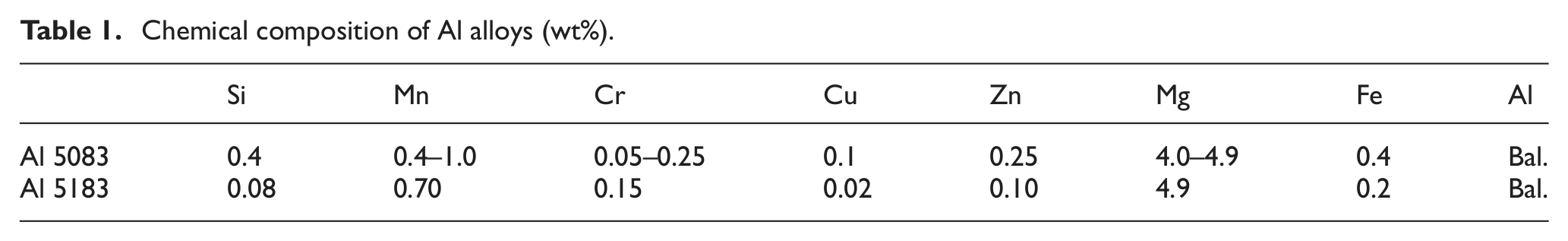
In the experiments, an Al 5083 plate with a thickness of 25 mm was used as the base material, and Al 5183 wires with diameters of 1.6, 2.4, and 3.2 mm were used for the filler. Table 1 shows the typical chemical composition of the Al 5083 and 5183 alloys. In the case of a single-wire welding process, three wire diameters were used. However, for the tandem-wire welding, only wires with a diameter of 1.6 mm were used. The tandem-wire welding was carried out using two wires fed into a common weld pool. The contact tips were electrically isolated, and the pulsed electrical power for each wire was staggered and synchronized in order to minimize the arc interaction.
Chemical composition of Al alloys (wt%).
Bead-on-plate welding was conducted in the flat position, and the contract tip-to-workpiece distance (CTWD) was set to 20 mm. A 33:67 mixture of Ar and He was used as the shielding gas, which was supplied at a flow rate of 40 L/min. The torch travel angle was 10° (forehand) for the single-wire welding and 0° (perpendicular) for the tandem-wire welding.
The Fronius TPS 5000 pulse inverter power source used in this study has a database of welding conditions that are referred to as synergic line. With Fronius equipment, there are synergic lines available for a given combination of process mode, weld wire–type diameter, and shield gas. Using this database, we selected appropriate current and voltage waveforms according to the given wire feeding rate. Therefore, prior to the high deposition experiments, the relationship between the wire feeding rate and the welding current was investigated by increasing the wire feeding rate at a constant welding speed of 0.250 m/min.
The bead shapes, mainly penetrations, were evaluated according to the welding parameters on the basis of two concepts—one was the increase in the wire feeding rate at a constant welding speed of 0.250 m/min and the other was the simultaneous increase in the welding speed and the wire feeding rate necessary about to maintain a constant deposition rate per unit weld length of 250 g/m.
In the tandem welding system, two TPS 5000 power sources were synchronized. The two longitudinally located welding arcs played different roles—the leading arc mainly obtained penetration through a strong arc and the trailing arc formed a flat bead by maintaining a long arc. For this purpose, in all tandem welding experiments, the feeding rate for the trailing wire was set to 80% of that for the leading wire. Moreover, the voltage of the trailing wire was set to 20% higher than the preset value for the single-wire welding.
Results and discussion
Welding current and deposition
In pulsed GMA welding, a stable drop transfer can be achieved for an average current less than the spray transition current. Pulsing parameters that determine the pulse waveform are shown in Figure 1. 23 There are several pulsing parameters such as base current, peak current, peak current time, and pulse frequency, but only the average current was used for specifying the current characteristics in this study.
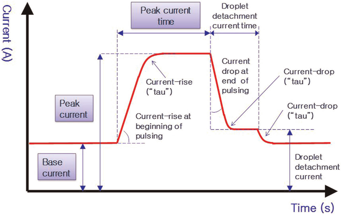
Current waveform and pulse parameters for pulse GMA welding. 23
After increasing the wire feeding rate at a constant welding speed of 0.250 m/min, we conducted the single-wire and tandem-wire weldings to investigate the relationship between the current and the feeding rates. As shown in Figure 2, the welding current exhibited a linear relationship with the wire feeding rate for each condition. It should be noted that, in the case of the tandem-wire process, the welding current and the wire feeding rate shown in Figure 2 indicate the sum of those of the leading and the trailing wires. At the same wire feeding rate in the case of the single-wire welding, a relatively high welding current could be achieved for the wire with the large diameter because the wire melting rate was proportional to the current density as follows 24
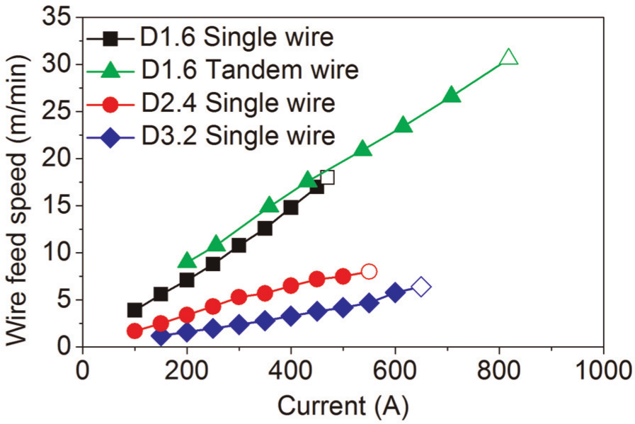
Relationship between wire feed speed and average welding currents.

where wm denotes the wire melting rate, a and b are the coefficients, j is the current density, and Le denotes the electrode extension.
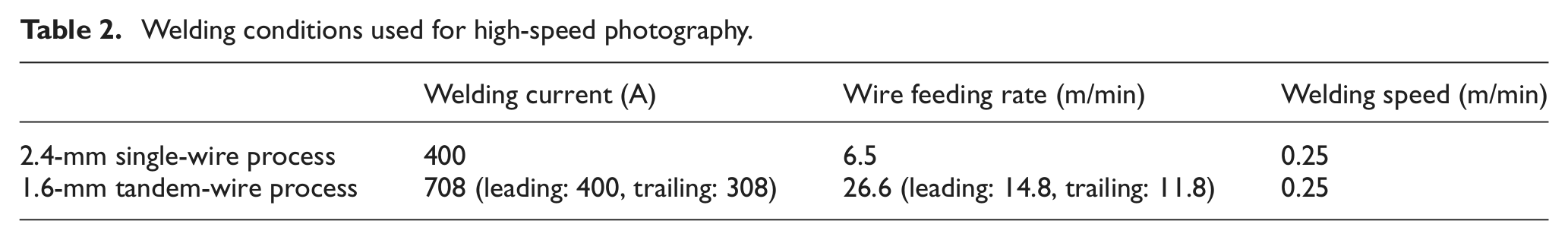
The hollow symbols used in Figure 2 indicate the formation of puckered bead. For instance, Figure 3 shows the bead shapes just before and after formation of puckered bead for the 1.6-mm single-wire process. In tandem-wire welding, a stable bead formation was possible when the current of the leading wire was up to 400 A and the sum of the leading and the trailing wire currents was below 700 A (Table 2). In the 2.4- and 3.2-mm single-wire processes, stable beads were formed with welding currents of up to 500 and 600 A, respectively.
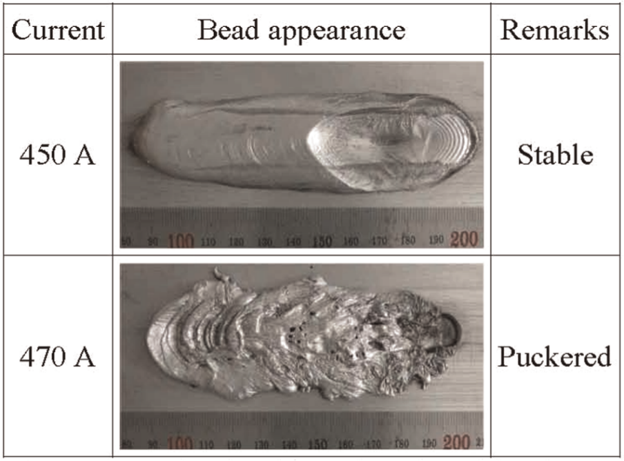
Example of stable and puckered beads (1.6-mm wire).
Welding conditions used for high-speed photography.
For a comparison of the deposition rates of the processes, the deposition rate according to the average current levels is presented in Figure 4. In the case of the 1.6-mm single-wire process, stable deposition was obtained up to 92 g/min. In the case of the 1.6-mm tandem-wire, 2.4-mm single-wire, and 3.2-mm single-wire processes, stable welds formed with depositions of up to 145, 92, and 126 g/min, respectively. Irrespective of the wire diameters, the relationships between the welding current and the deposition rate were almost the same, but the maximum deposition without formation of puckered bead was dependent on the wire diameter. The tandem-wire process achieved the highest deposition rate although the cross-sectional area of the 3.2-mm wires was two times the sum of the cross-sectional area of 1.6-mm tandem wires. As depicted in the study by Miyazaki et al., 7 a wire with a large diameter could suppress the formation of puckered bead to a certain extent by reducing the arc pressure, but the multiple-wire welding was more effective than the single-wire welding using a large-diameter wire.
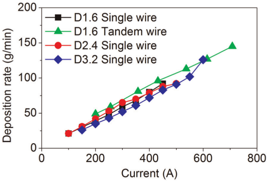
Relationship between deposition rate and average welding current.
Penetration
For a comparison of the penetration characteristics, welding experiments were conducted with two conditions. One is fixing a travel speed constant as 0.250 m/min, during the increasing average current, while the other is adjusting a travel speed to keep a constant deposition rate per unit length of 250 g/min during the increasing average current.
For the case of a constant welding speed, the cross-sectional beads for each process are shown in Figure 5, and the measure penetration depth is shown in Figure 6. The penetration depth increases with an increase in the welding current. By using the single-wire welding process with a wire having a diameter of 3.2 mm, we obtained a maximum penetration depth of 19.7 mm because of the highest welding current. For the same welding current, a relatively deep penetration was formed when a relatively thin welding wire was used. The penetration depth in the case of the tandem-wire process at the same welding current was lower than that of any single-wire process. Moreover, the maximum penetration depth of the tandem-wire process was comparable to that of the 1.6-mm single-wire process.
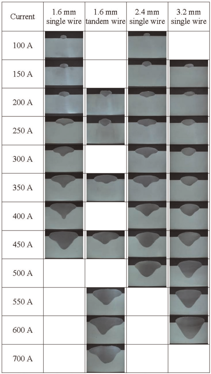
Cross-section shapes according to various average currents.
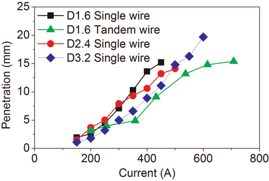
Relationship between penetration and average welding current.
When welding at a constant welding speed, the heat input was proportional to the welding current. In the case of a constant deposition rate per length, by simultaneously increasing the welding currents and travel speeds, we could maintain the heat input per unit length at a constant value.
Figure 7 shows the measured penetration depths for constant deposition rate conditions compared with those for the constant welding speed conditions. The welding speed should increase with an increase in the welding current in order to maintain a constant deposition rate per unit length. For welding with a 3.2-mm single wire, a high welding speed due to a high welding current affected the stability of the weld pool and led to a decrease in the maximum welding current, thereby avoiding formation of puckered bead. In the case of the single-wire processes, the penetration depths were almost the same for both cases except the highest welding current condition in the constant deposition rate case. Under this condition, the wire diameter was 2.4 mm, the welding current was 500 A, and the welding speeds were 0.250 and 0.366 m/min at constant speed and deposition rate, respectively. This discrepancy originated from the large difference in the welding speeds. Furthermore, there was a remarkable difference in the penetration at the high-current ranges in the case of the 1.6-mm tandem-wire process. For example, the welding speed for a welding current of 708 A was 0.250 and 0.578 m/min in the cases of constant speed and deposition rate, respectively. In these high-welding-speed conditions, the reduced heat input resulted in a relatively low penetration.
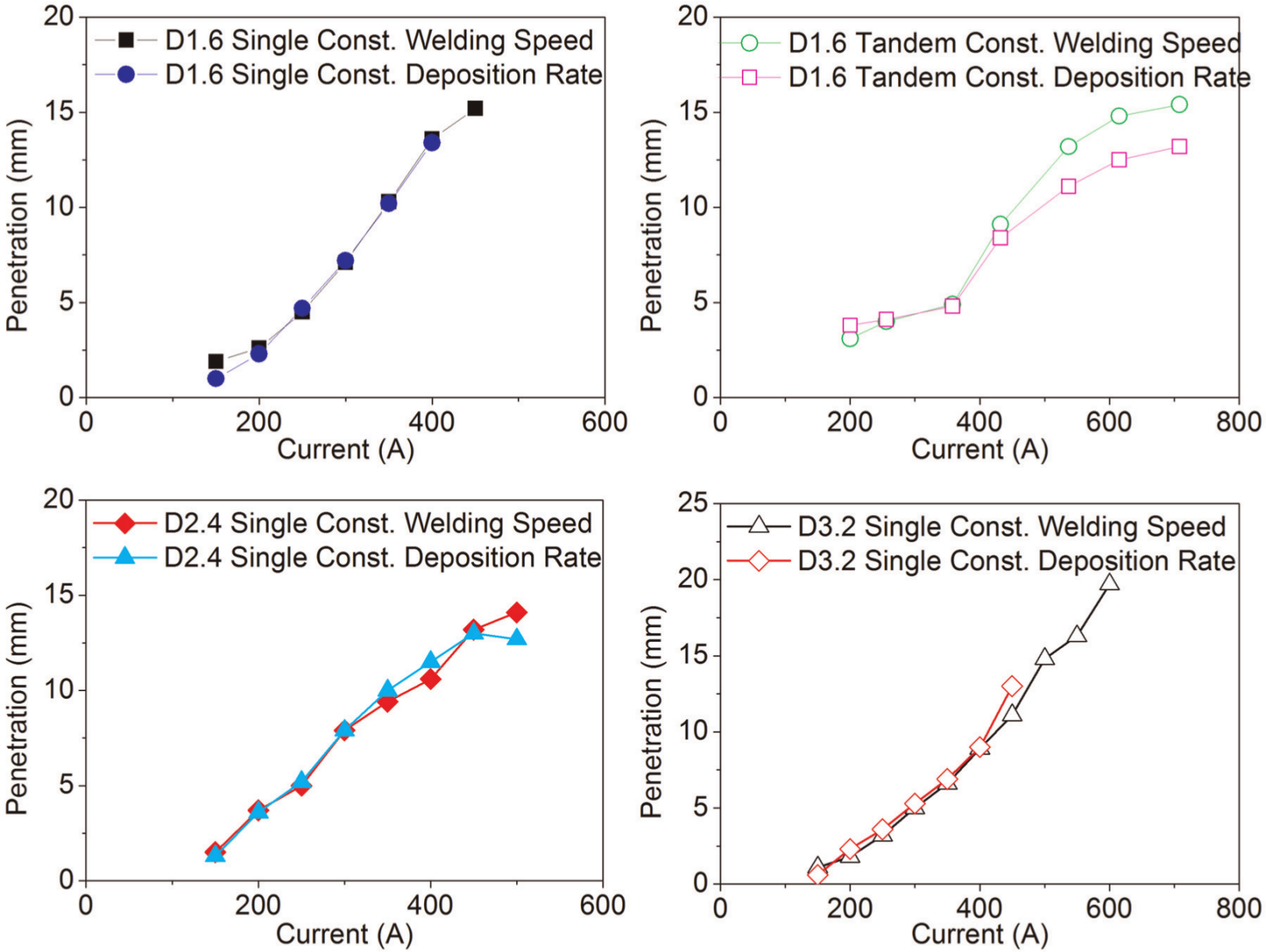
Penetrations for constant welding speed and constant deposition rate conditions.
Spatter generation
In the experiments described above, a number of spatter particles were generated for high-current welding conditions using a tandem-wire welding process as compared to that using a single-wire process. Figure 8 shows the high-speed photographs for the 1.6-mm tandem-wire and 2.4-mm single-wire welding processes.
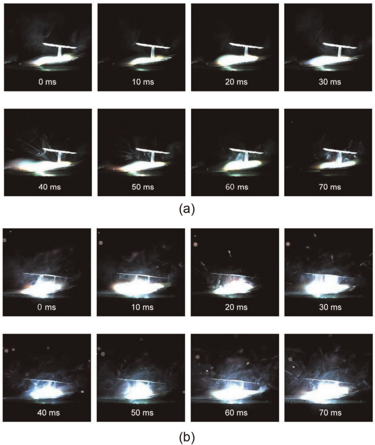
Spatter generation characteristics: (a) 2.4-mm single-wire process and (b) 1.6-mm tandem-wire process.
In the tandem-wire welding process used in this study, the pulsing arcs of the master and slave power source are digitally controlled as out of phase in order to avoid the deflection of the welding arc and the droplet transfer by the electromagnetic interaction between the two adjacent arcs.25,26 Nevertheless, the previous study for welding steel using a tandem-wire system showed that the arc and droplet attraction could not be avoided at a high-current level. 27
The spatters generated during the high-current welding with a tandem-wire process may be due to the interference between the leading and the trailing welding arcs. To confirm this, a more detailed observation of the droplet transfer was conducted by recording the current waveform signals. As shown in Figure 9, the hanging molten metal on the end of the trailing wire was attracted and detached during the arcing time of the leading arc, and it could not be impinged into the molten pool.
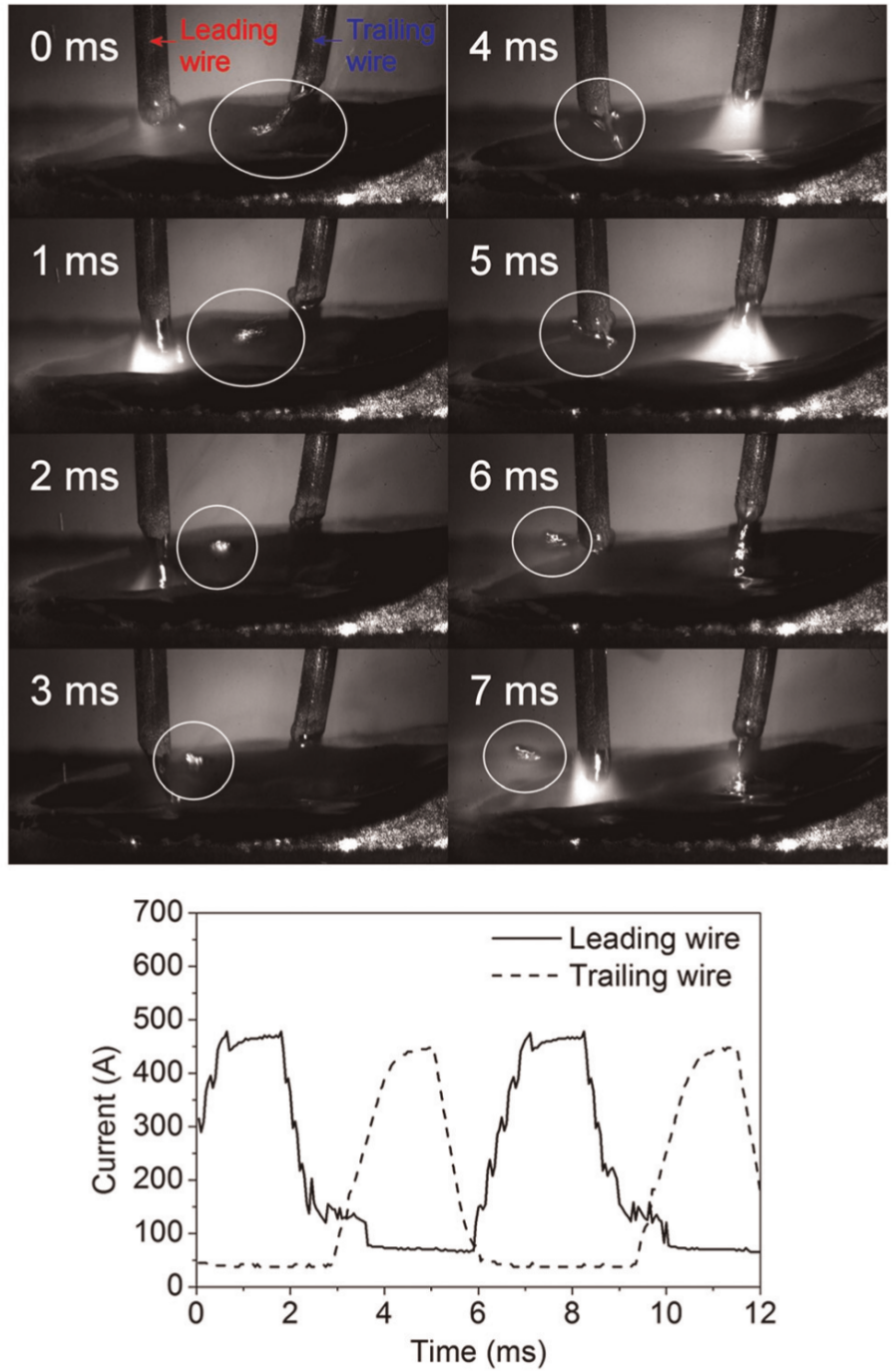
Arc interaction phenomena during tandem-wire process and current waveform for each wire.
Conclusion
In this study, high-current welding characteristics were evaluated for single-wire welding with welding wires with different diameters and tandem-wire welding on the Al 5083 alloy, and the following conclusions were derived:
The welding current showed a linear relationship with the wire feeding rate. In the case of the single-wire welding, the use of a wire having a large diameter enabled high deposition welding without formation of puckered bead. Moreover, tandem-wire welding was more effective in avoiding formation of puckered bead, which is considered because of reducing the arc pressure.
The penetration depth increased with an increase in the welding current. For the same welding current, a relatively deep penetration was formed by using a relatively thin welding wire. The welding current and speed affected the penetration depth; however, if the welding speed was not too high, the penetration depth was determined only by the welding current.
More spatter generation was observed for high-current welding during the tandem-wire process than during the single-wire process. In spite of the staggered pulsing, the droplets on the wire formed when the base current was activated (this current was relatively high because of the high average current) were attracted by the pulsing current of the other wire; this attraction resulted in spatter generation.