
Abstract
Cutting tool temperature plays a key role in machining processes due to its effect on tool life and material removal rate, especially during high-speed machining of hard-to-cut materials. Several methods have been introduced to measure temperature of static objects in machining, such as workpiece in milling operation or cutting tool in turning operation. However, a few methods have been proposed to measure cutting tool temperature in milling process. In this article, we investigate cutting tool temperature in slot milling process. A wireless temperature measurement system with embedded thermocouple is developed to monitor and record cutting tool temperature. A series of experiments for slot milling of AerMet 100 steels are designed to measure cutting tool temperature with the wireless temperature measurement system. The cutting experiments are carried out under cutting speeds from 500 to 1750 m/min. The measurement results reveal that milling tool temperatures increase first and then decrease as cutting speed increases, and the peak temperature of milling tool appears at a critical cutting speed of about 1250 m/min. The effects of cutting speed on cutting tool temperature and tool wear are discussed.
Introduction
AerMet 100 is a secondary hardening type of ultrahigh-strength steel (∼2000 MPa), and it has excellent fracture toughness (140 MPa/m1/2), combined with excellent resistance to stress corrosion cracking and fatigue. 1 Based on these properties, AerMet 100 has been widely used to fabricate important heavy-loaded components in the aviation industry and military equipment such as aircraft landing gear.
A little research on machinability and tool wear of AerMet 100 has been done in recent years. Through dry machining operations of AerMet 100, D.V. Squire et al. 2 concluded that the uncoated carbide tools failed mainly by cutting edge chipping due to the thermal breakdown. However, study about machining temperature of AerMet 100 is rare. Su and Liu 3 conducted dry high-speed machining experiments of AerMet 100 with cutting speeds from 250 to 7000 m/min to investigate the influence of cutting temperature on tool wear. They obtained the cutting temperature through chip color recognizing method proposed by Venkatesh et al. 4
The temperature distribution in cutting tool is a key factor in machining processes due to its determination effect on mode of tool wear and material removal rate. Komanduri and Hou 5 presented an analytical model for temperature rise in the cutting tool, considering the combined effect of shear plane heat source and tool–chip interface frictional heat source. Huang and Liang 6 presented a cutting temperature model based on non-uniform heat intensity and partition ratio. The temperature beneath the rake face of a cutting tool was calculated by Sato et al., 7 using Green’s function approach in end milling. Jiang et al. 8 modified the model of tool temperature proposed by Stephenson and Ali 9 during interrupted cutting and designed a set of interrupted cutting experimental installation to verify the modified model.
Experimental investigation is another important way to study cutting temperature and it is also a necessary way to validate temperature results from other methods. A few methods have been proposed to obtain cutting tool temperature during milling process. Tool insert temperature measurement in milling is more challenging than that in turning. Sato et al. 10 developed an infrared radiation pyrometer with two optical fibers to measure the temperature of cubic boron nitride (CBN) tool face in end milling. A wireless sensor integrated tooling system was presented by Suprock et al. 11 for temperature measurement. Several criteria were proposed for the wireless temperature measurement system to be accepted by industry. A similar wireless temperature measurement system for rotating cutting tools was proposed by Le Coz et al., 12 incorporating a data acquisition and conditioning system and a wireless transmitter unit into a special tool holder. It was demonstrated that the presented system allowed to perform a maximum speed of 20,000 r/min, with acquisition frequency of 1 kHz and accuracy of 1 °C. Kerrigan et al. 13 proposed a wireless temperature measurement system and integrated it into a cutting tool holder via a thermocouple embedded in the cutting tool to monitor machining process temperature.
The purpose of this article is to investigate the cutting tool temperature by experimental method during slot milling of AerMet 100 steel. A wireless temperature measurement system with embedded thermocouple in milling tool is first developed to monitor and record temperature during slot milling cutting process. Series of experiments are then carried out to obtain temperature inside cutting tool at different cutting speeds. The influence of the cutting speeds on the tool temperatures is discussed, and chip color is analyzed to determine chip temperature. Cutting tool wear is also investigated, and a cutting speed of 1000 m/min is suggested during slot milling of AerMet 100. Finally, general conclusions and perspectives are proposed.
Development of wireless temperature measurement system
A wireless temperature measurement system with embedded thermocouple in slot milling tool is developed. Shown in Figure 1, the temperature measurement system mainly consists of three functional modules: a data acquisition as well as processing module, a wireless transceiver module and a data recording module.
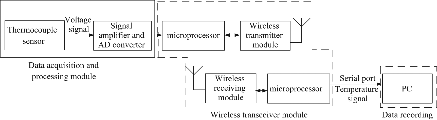
Wireless temperature measurement system.
The data acquisition and processing module based on a thermocouple embedded in the milling tool is shown in Figure 2. Four mounting holes are drilled in the milling tool to install the thermocouple sensor. The electric voltage converted by temperature differences is amplified and converted to digital signal, and then, a wireless transceiver module transmits and receives the digital signal. According to the characteristics of components, this wireless temperature measurement system has a resolution of 0.25 °C and a measuring range of 0 °C–1200 °C. Through serial ports, the measured digital temperature signal is transferred to PC for data recording and displaying.
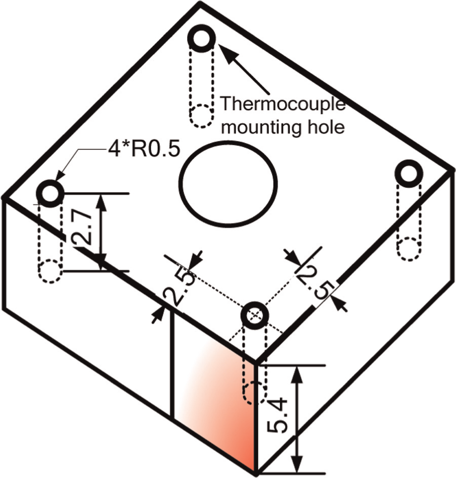
Milling tool with thermocouple sensor mounting hole.
Before the wireless temperature measurement system is applied in experiments, it is calibrated with a calibration furnace YG-5. A normal K thermocouple is connected with temperature controller SR23 to provide temperature controlling feedback signal, and the tested thermocouple is connected with the wireless temperature measurement system. After calibration, the wireless temperature measurement system has relatively high accuracy, and the error is not more than 1 °C in the measuring range.
Modeling of tool temperature during slot milling
The slot milling process consists of several periodical characteristics, such as cutting force and time-varying heat source. 8 Consequently, a thermal model for temperature of slot milling tool is developed with time-varying heat source. As shown in Figure 3, time-varying heat flux due to changed uncut chip thickness is imposed on the tool rake face, and the uncut chip thickness hc varies from 0 to maximum when the tool cuts in and out of the workpiece.
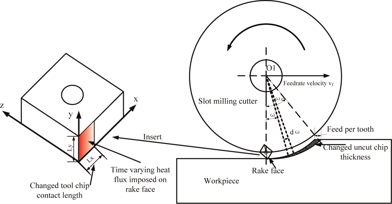
Time-varying heat flux on the rake face during slot milling.
Modeling of milling tool temperature
Figure 4 shows a whole slot milling period as interrupted cutting is divided into cutting time and non-cutting time, subsequently heating time and cooling time for tool insert. Heat radiation is regardless and thermal properties of the tool insert are considered as independent of temperature. It should be noted that with temperature-dependent thermal properties, the result is accurate but computationally difficult due to nonlinear governing conduction equation. Jen et al. 14 proposed a nonlinear solution of the cutting tool temperature field with temperature-varying thermal properties. No serious error was reported for a carbide cutting tool with constant thermal properties. The simplification is acceptable when the thermal properties of tool material do not depend strongly on temperature, such as tungsten carbide. For the applied tool material of carbide alloy in this article, it is acceptable to consider the thermal properties as independent of temperature. Heat radiation is regardless due to its small amount.
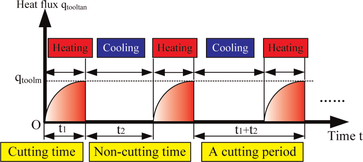
Heat flux in the milling process.
The governing equation and boundary conditions for the temperature of milling tool insert are given by equations (1) and (2)


where
According to Sato et al. 7 and Jiang et al., 8 the temperature field T(x, y, z, t) of tool insert could be obtained as equation (3)
where T is the temperature of any point in the tool insert at any time, ktool is the thermal conductivity of tool material, αtool is the thermal diffusivity of tool material, c is the ratio of tool–chip contact length and uncut chip thickness, fz is the feed per tooth, ω is the instantaneous contact angle, qtoolm is the maximum heat flux generated at the maximum uncut chip thickness point and Lx and Ly are the dimensions of heat source. Green’s function θGR for an instantaneous heat source over the path 0 ⩽ x ⩽ Lx, 0 ⩽ y ⩽ Ly is

where


are parameters with units of length.
Effect of cutting parameters on tool temperature
The proposed model shows the variation in tool temperature in the milling process. The heat source in the model is considered as time-dependent but spatially uniform, which accords with the milling process and reduces the calculation load greatly. The proposed model of milling tool temperature contains the cutting parameters of uncut chip thickness, feed per tooth and cutting speed. The effect of these cutting parameters on tool temperature could be calculated and analyzed by this model. The cutting time in one period, τ1, in the model decreases as the cutting speed grows, which makes the heat source of higher frequency and shorter duration.
The influence of radial depth of cut on temperature is given by Ueda et al. 15 that the tool temperature increases with the increase in radial depth of cut. Compared with cutting speed, the effects of radial depth and feed per tooth on the tool temperature are much smaller, 15 while the effect of cutting speed on milling tool temperature is indirect, through the influence of three effects. As the cutting speed increases, more heat is generated per unit time due to increased metal deformation; partition ratio of generated heat into cutting tool decreases; and heat convection on cutting tool face becomes significant. The temperature increases when the first effect dominates the tool temperature variation, and the temperature decreases when the last two dominate. The tool temperature variation is a comprehensive result of these three effects.
Tool temperature measurement experiments
Experimental work was carried out to measure cutting tool temperature by developed wireless temperature measurement system during slot milling process. The workpiece of AerMet 100 was made into sheet specimen with a thickness of 2.5 mm and a length of 70 mm. The sheet specimen was cut on the AVE-V500 CNC vertical machining center with uncoated slot milling insert SNHX12L5PZTNGP K110M from Kennametal. The tool holder is a type BT40CS40080M with slot milling cutters 4.96164-210. The experimental setup is shown in Figure 5, which indicates that the wireless transmitter module was fixed on the tool holder and the thermocouple sensor was installed into the tool insert. High-temperature structure adhesive HT-CPS covered the top of the sensor to avoid damage by the cutting chips. A Kistler dynamometer was applied to detect changes in cutting force during cutting process.
Experimental setup.
Slot milling experiments were carried out under a constant feed per tooth fZ of 0.1 mm/Z, a radial depth of cut of 1.5 mm and an axial depth of 2.5 mm. Cutting speeds were the only variable of machining parameters in this study, varying from 500 to 1750 m/min. Temperatures of tool inserts were measured at different cutting speeds by the developed wireless temperature measurement system, and cutting forces were obtained by the Kistler dynamometer during dry milling processes. Tool insert was changed after each cutting, and wear area of cutting insert was observed by an optical microscope Keyence VHX600E. Chip was collected and its color was observed to evaluate tool–workpiece interface temperature.
Results and discussion
Cutting temperature of tool insert
Shown in Figure 6, milling tool temperatures are obtained at different cutting speeds. Figure 6 shows that temperature of measured point in the tool insert increases first to a maximum value and then decreases slowly as the cutting speed grows. The maximum temperature of the measured point is about 60 °C, appearing at the cutting speed of 1250 m/min. The feed rate increases as the cutting speed grows on circumstance that the feed per tooth keeps constant, and subsequently time interval between the initial temperature and the maximum temperature decreases. 16 It must be mentioned that the measured point for the reported temperature is inside the tool insert, and the distance away from the cutting tool face is about 2.5 mm. The measured temperature does not indicate the general meaning of cutting temperature, which generally refers to the temperature of the primary deformation zone and tool–chip interface. 5 The obtained temperature result could be used to investigate heat flux by inverse heat conduction method. 17
Measured temperature profiles of tool insert versus cutting speed.
To validate the results obtained by this article, Table 1 presents the data of tool temperature, measurement method, cutting speed and workpiece materials by some researchers. Table 1 indicates that temperatures on the tool face and tool–chip interface are much higher than that inside the tool.
Comparison of milling tool temperature from scientific literature.
CFRP: carbon fiber–reinforced polymer.
It is reported by Sato et al. 7 that the tool temperature decreases with increasing depth from the rake face. Here, the depth means the distance inside the milling tool from the rake face. Compared with the temperature on milling tool face, 15 the temperatures obtained in this article seem to be lower due to larger depth. Milling tool temperature distribution at different depths based on the proposed model is calculated under certain parameters, as shown in Figure 7. The calculation results indicate that the temperature distribution near the milling tool face has an intense temperature gradient. The maximum temperature falls from 452 °C to 195 °C, when the depth grows from 0.1 to 1.0 mm. Milling tool temperature stays under 100 °C at depth of 2.0 mm or larger, which validates the experimental results. Also, the measured temperature of milling tool in this article agrees with the experimental result of Kerrigan and O’Donnell. 18 They obtained milling tool temperature using a wireless tool-integrated process monitoring sensor.
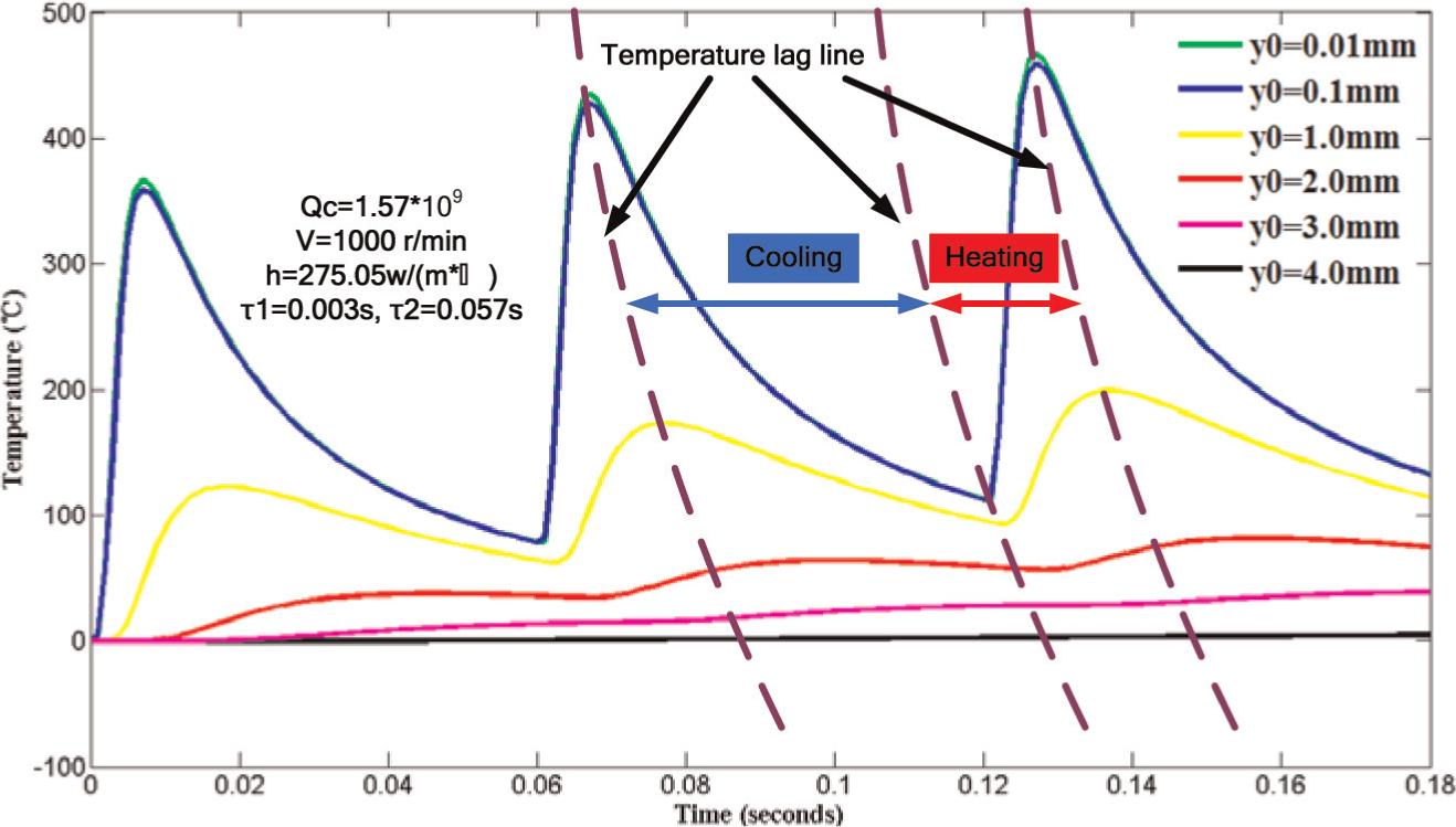
Temperature rise depending on depths in the milling tool.
The wireless temperature measurement system used in the investigation basically realized measurement of cutting tool temperature during milling processes. The data acquisition and processing module and wireless transmitter module are installed in the two locating slots of the tool holder, which are to minimize the unbalance degree and subsequent damage to spindle especially at high rotating speeds. According to Suprock et al., 11 several criteria for the wireless temperature measurement system are met. An acquisition frequency of 20 Hz is set at the cutting speed of 1750 m/min. It is reported by Werschmoeller 19 that highly transient heat input with frequency of 100 Hz will become virtually indistinguishable from constant heat input with a distance of 1 mm or more, which is due to limited heat dissipation speed and heat pulse damping caused by the tool insert material.
Chip color analyzing
As mentioned in the above section, the temperature of tool insert decreases when the cutting speed grows after 1250 m/min. In order to investigate where the other heat flows, cutting temperature of the chip is determined by chip color recognizing. 4 It is found that different iron oxides are produced by iron in the chip reacting with oxygen in the air at different cutting temperatures. Generally, there are three iron oxides yielded: FeO in blue, Fe2O3 in red or golden and Fe3O4 in dark in color. The Fe3O4 is formed at temperatures below 570 °C, and FeO is formed at temperature above 570 °C. When the temperatures are much higher than 570 °C, Fe2O3 is formed by further oxidizing of FeO. So, chip temperature could be evaluated by chip color, though it is not very accurate due to the influence of colors of other oxides.
The chips of AerMet 100 at different cutting speeds shown in Figure 8 are observed by an optical microscope Keyence VHX600E. It is found that the dominant color of chip changes gradually to golden and blue from dark and blue as the cutting speed increases, which means that the temperature of the chip grows and more heat flows into the chip.
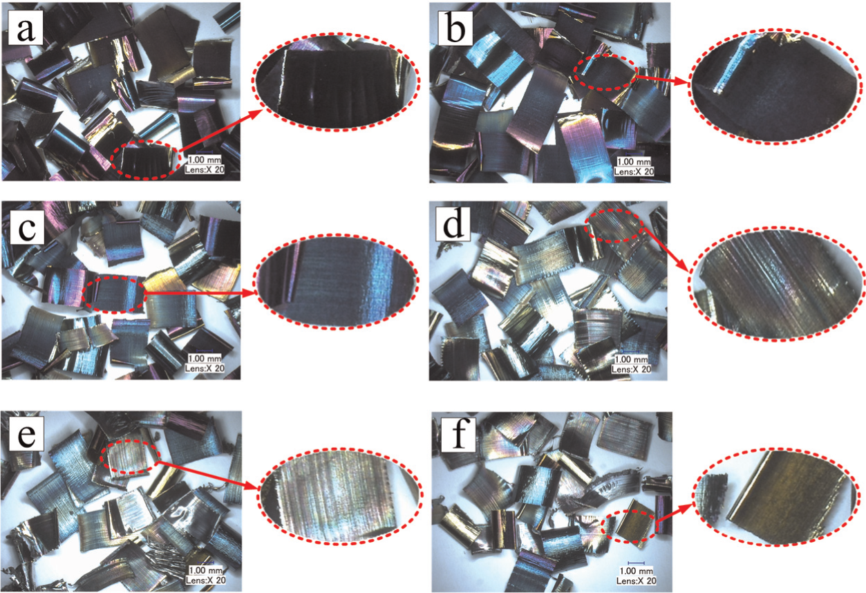
Chips at different cutting speeds: (a) V = 500 m/min, (b) V = 750 m/min, (c) V = 1000 m/min, (d) V = 1250 m/min, (e) V = 1500 m/min and (f) V = 1750 m/min.
Cutting tool wear
It was claimed by Su and Liu 3 that the cutting temperature highly influenced the tool wear during machining of AerMet 100. Tool insert is examined and changed after each cutting test. Crater wear in the rake face is difficult to observe, and we choose the flank wear as a tool life criterion. The flank wear is observed and measured by an optical microscope Keyence VHX600E, which could be used to read the average flank wear land width. Figure 9 shows the flank face wear of tool inserts at different cutting speeds. Scanning electron microscope (SEM) is carried out to analyze the tool wear mechanism of chipping and fracture, and also the energy dispersive X-ray analysis (EDAX) is carried out to analyze the chemical elements of the tool wear surfaces.
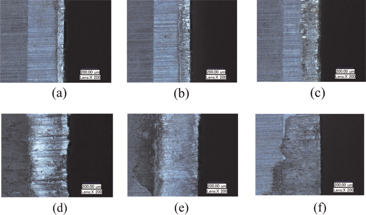
Flank wear of tool inserts at different cutting speeds: (a) V = 500 m/min, (b) V = 750 m/min, (c) V = 1000 m/min, (d) V = 1250 m/min, (e) V = 1500 m/min and (f) V = 1750 m/min.
At low cutting speeds, the bright band at the flank face is found and tool wear shown in Figure 9(a) and (b) is not obvious due to low cutting temperature. The flank wear width is between 0.1 and 0.15 mm at low cutting speeds of 500 and 750 m/min. SEM of the tool wear (Figure 10(a)) shows that micro cracks appear on the flank face around the cutting edge, and this indicates that micro chipping has spread over the flank face. At low cutting speeds, the tool wear mechanism is mainly micro chipping.
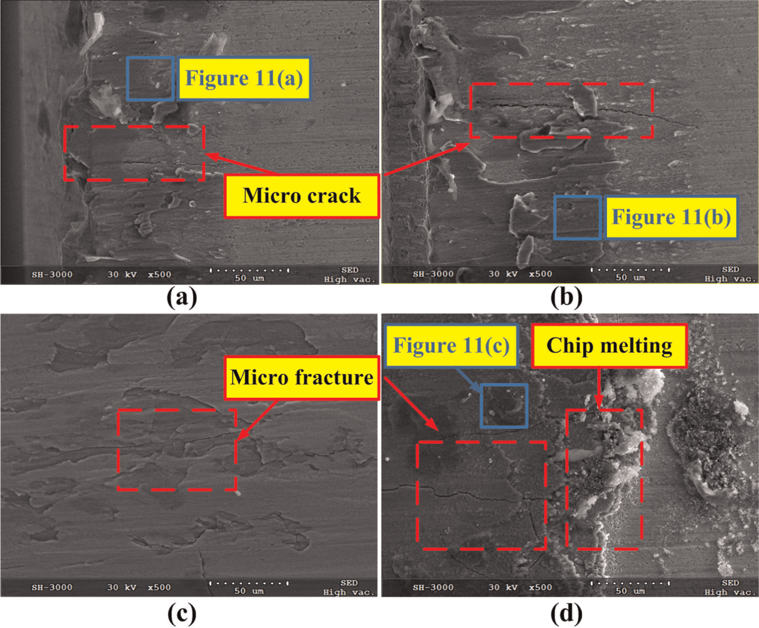
SEM photographs of the worn flank surfaces at different cutting speeds: (a) V = 500 m/min, (b) V = 1000 m/min, (c) V = 1250 m/min and (d) V = 1500 m/min.
The flank wear width grows rapidly when the speed is between 1000 and 1250 m/min. At the speed of 1000 m/min (Figure 9(c)), micro breakages and micro grooves due to abrasion wear of the milling tool appear on the cutting face, and this means intense friction between cutting tool and workpiece. The existence of Fe, Cr and Co from the EDAX results (Figure 11) indicates that cold welding has happened on the tool flank and workpiece interface, as Fe, Cr and Co are the main elements of AerMet 100. By comparison, the content of Fe and Cr in Figure 11(a) is smaller than that in Figure 11(b), which indicates that workpiece material adhered on the worn flank face increases. After that, the amount of adhered material on the flank face decreases.
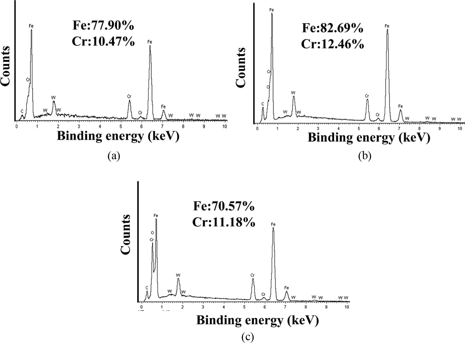
EDAX results of adhered material in Figure 10(a), (b) and (d).
SEM result of the flank wear at the speed of 1250 m/min (Figure 10(c)) shows that flake of tool material has peeled off, and the remaining surface chips maybe due to thermal shock. At cutting speeds of 1500 m/min, the flank wear width has a minor reduction, but fractures spread all over the flank face as shown in Figure 10(d). The wear of the flank face at speeds higher than 1250 m/min stays similar to that at 1250 m/min, but with different wear degrees.
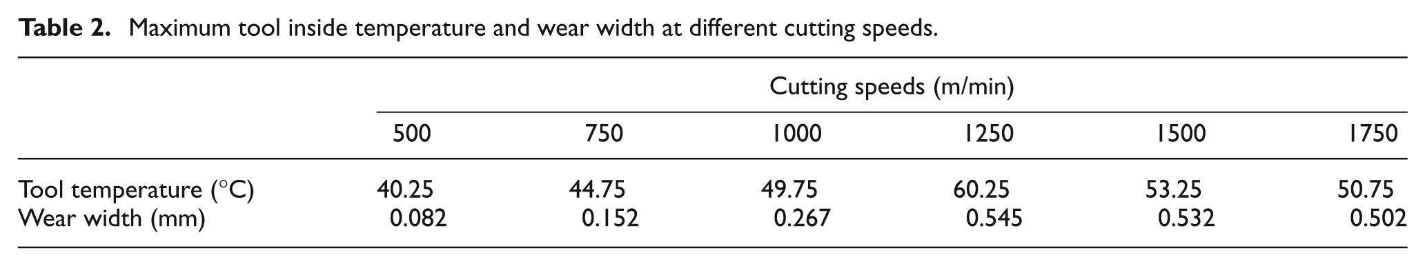
The maximum tool temperature and tool wear width at different cutting speeds are given in Table 2. Table 2 indicates that the wear characteristics of cutting tool cannot be explained solely by cutting speed, as it is influenced by the cutting temperature to a greater degree. This implies that tool wear is developed by an abrasive process at low cutting speeds and by a thermally activated adhesion mechanism at high cutting speeds. A cutting speed is suggested to be under 1000 m/min during slot milling of AerMet 100.
Maximum tool inside temperature and wear width at different cutting speeds.
Discussion
It is difficult to achieve accurate measurement of tool insert temperature during slot milling, and the proposed wireless temperature measurement system basically realizes the temperature measurement of the rotating tool insert. Compared to an acquisition frequency of 1 kHz by Le Coz et al., 12 the frequency applied in this article is not high enough for the cutting speeds of 1750 m/min and higher. Due to insufficient response speed of applied thermocouple, it is impossible to observe the periodical effect of time-varying heat source in the experiments. The obtained temperature of tool insert seems much lower than the reported results. 10 Several reasons are proposed: the measured point is relatively far away from the cutting edge and the spatial temperature gradient in the tool insert is high; the temperature of tool insert in the interrupted cutting is much lower than that in the continuous cutting, and there is more time for the tool insert to cool down in a cutting period owing to the applied slot milling cutter, which is with a ratio of cutting time to non-cutting time of 1/45. The future work would include using a sensor as thin film thermocouple 19 with faster response time and being closer to the cutting edge.
The temperature of tool insert increases first and then decreases after a peak point as the cutting speed grows. This is contrary to Dewes et al.’s 20 findings and partly agrees with Salomon’s theory 21 for milling tool temperature. As mentioned, the effect of cutting speeds on milling tool temperature is indirect, and three effects are proposed. The rise in the tool temperature is because more heat is generated as the cutting speed increases. 16 The drop in the temperature is mainly caused by the decrease in heat partition ratio into tool, 8 which means that there is not enough time for generated heat to transfer to tool insert before more heat is taken away by the chip. The chip color analyzing verifies that more heat flows into the chip and the temperature rises as the cutting speed grows. In addition, the heat convection also makes the temperature decrease. It could be concluded that the first effect dominates the tool temperature variation at low cutting speeds, which make the milling tool temperature increase; the last two effects dominate after a critical cutting speed. In order to fully test Salomon’s findings that temperature reduces at higher cutting speeds, a machine with higher spindle speeds would be required. 20
Conclusion
Wireless temperature measurement system is developed to obtain temperature of tool insert during slot milling. There are still some works to do to improve its behavior such as acquisition frequency, response speed and accuracy.
Series of experiments for slot milling of AerMet 100 are carried out to obtain temperatures of tool insert at different cutting speeds. A peak temperature of tool insert at the measured point is reported as about 60 °C. Chip color analyzing verifies that the temperature of the chip increases as the cutting speed grows.
The temperature of tool insert increases first and then decreases after a peak point as the cutting speed grows. A critical cutting speed for the tool insert temperature is considered as 1250 m/min approximately in the slot milling of AerMet 100.
Cutting tool wear is investigated, and a cutting speed of 1000 m/min is suggested during slot milling of AerMet 100.
The tool insert temperature is affected by the combination of two effects. Salomon’s hypothesis is applicable to the temperature of tool insert during slot milling of AerMet 100.
Footnotes
Appendix 1
Declaration of conflicting interests
The authors declare that there is no conflict of interest.
Funding
This work was supported by grants from Tai Shan Scholar Foundation. This work also received the financial support from the National Natural Science Foundation of China (51425503, 51375272, U1201245) and the Major Science and Technology Program of High-end CNC Machine Tools and Basic Manufacturing Equipment (2014ZX04012014).