
Abstract
This article presents an operation planning method based on a dynamic feature concept for 2.5-axis numerical control machining of complex aerospace structural parts. A dynamic feature consists of information about the machining effects on the feature between various operations carried out during production. To get the information about the machining effects of a machining operation, non-machining configuration spaces are constructed by detecting the intersection regions within the offset machining boundaries. Each non-machining configuration space refers to the machining effect (either an overcut or undercut). In the proposed operation planning method, dynamic features based on a preliminary process plan are first established. Then, an iterative procedure for adjusting the preliminary machining operations is put forward using updated dynamic feature information with various machining effects transitions and validity constraints during different operations. The method is tested using an aircraft structural part in a feature-based numerical control programming system called FBM_NUAA, which has been used in a large aerospace manufacturing company.
Introduction
Process planning is the bridge to link design and manufacturing, making the decisions for optimal process plans to convert designers’ intents to physical parts economically and competitively, and plays an important role in the efficiency and quality in manufacturing activities. 1 Although research about process planning has continued for decades and has achieved significant progress, process-planning systems are still not widely applied in industry. It is especially difficult with the trend of larger size and more complex structures of aerospace products and increased machining requirements. Feature-based technologies, including feature-based design and feature conversion and recognition, could enable the integration of computerised design and manufacturing support systems. Features could be used for the modelling of information and knowledge such as machine tools, cutting tools, parameters, operations and sequencing, thus widely implemented in process-planning systems.
However, current commercial systems only represent the final state of features, that is, the final manufactured features that meet the design specifications. Feature models once defined normally remain consistent in the whole product lifecycle, called static features in this article. However, it is difficult to plan the appropriate manufacturing strategies to achieve the required quality just using the static feature information because feature information changes between various manufacturing operations. In practice, most machining operation plans generated based on the static feature model need significant manual corrections to reflect the real feature states. In the authors’ previous reports, 2 feature definition is extended to addressing the whole machining process, where a feature model consists of interim feature states and is called a dynamic feature compared with the static feature models in current computer-aided design (CAD)/computer-aided manufacturing (CAM) systems. The actual geometry and conditions of an interim feature are the results of various manufacturing operations called machining effects in this article.
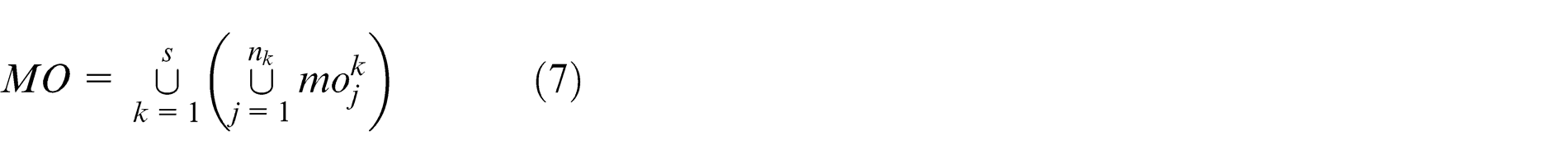
In this article, the dynamic feature concept is used for machining operation planning. To get the machining effects, non-machining configuration spaces (NMCSs) are constructed by detecting intersection regions within the offset machining boundaries. Each NMCS refers to an undesired machining effect like overcut and undercut. In the proposed operation planning method, dynamic features are first established based on a preliminary process plan selected from traditional process plans. Then, an iterative procedure for adjusting the preliminary machining operations is put forward by considering the updated dynamic feature information with machining effects transitions (METs) and validity constraints (VCs). Section ‘Review of related work’ reviews the related research work. Section ‘Representation of machining effects based on configuration space method’ discusses the NMCS-based undesired machining effects detection method. In section ‘The dynamic feature–based operation planning method’, the dynamic feature–based operation planning method is described. System implementation using an aircraft structural part is presented in section ‘System development and application’. Conclusions are summarised in section ‘Conclusion’.
Review of related work
During the last two decades, variable approaches to the generation of optimised manufacturing process plans for complex structural parts have been developed. Feature-based technologies have been regarded as the crucial topic for the integration of CAD/CAM systems. Parts with various complex structures might be represented by a limited number of feature types and mapped with certain manufacturing knowledge. 3 Thus, most of the computer-aided process-planning (CAPP) systems available now are feature-based or require a feature-based part model input. Research in feature technology in process planning mainly focused on the definition or classification of features to represent complex structural parts, the methods to extract features from these parts and the way to obtain optimal process plans based on features.
Features could be defined or classified with different aspects in process planning. Features could be defined based on the similarities in geometry shapes, like ISO 10303-224:2006, 4 and feature categories used in reported research works.5–7 Another typical definition is based on machining methods. In this kind of definitions, features are gathered based on the similarities in machining methods. For example, a hole or profile both could be defined as drilling features since they could be machined by drilling operations. Feature definitions used in by Sridharan and Shah 8 and most commercial CAM systems like NX and CATIA are based on this idea. With their research projects, representation of complex structural parts became feasible.
The research in feature extraction is mainly focused on identifying complex intersecting features widely existing in complex parts. In recent years, feature extraction approaches based on the combination of geometry reasoning for process planning have been developed.9,10 With this idea, interpretation of complex intersecting features could always be obtained since more constraints and rules are available in process-planning stage. Feature models are associated with manufacturing knowledge like set-up plans, cutter selection and cutting parameters.
Feature-based process-planning methods are used to generate optimal process plans based on these rules or reasoning logics converted from experiences and knowledge of human experts automatically. 11 There are several typical issues about the research of feature-based process planning. Cutter selection is one of the most important tasks because the determination of cutting parameters, machining time and cost is influenced by the cutter. Maropoulos and Baker 12 developed a cutter determination technology based on feature geometry. Tool selection was integrated with design system using features. Tool selection involved converting the information associated with each feature during the design stage into machining operation requirements, which in turn was used to query a database to extract all tools that may be used to complete a given operation. You et al. 13 introduced a cutter selection method for pocket feature. In his method, the combination of the optimal tools for the whole machining process of pocket feature could be obtained by simplifying three-dimensional (3D) features into two-dimensional (2D) boundaries.
Operation sequencing is another important issue in process planning since an unreasonable machining sequence may lead to deformation, undercut or overcut. A mathematical model for hole-making sequencing was put forward by Hao and Ma. 14 In their research, the features framework maps the manufacturing features to the required machining operations. Then, the mathematical sequencing model generates an optimal machining sequence by minimising the number of tool changes. Wang et al. 15 treated the machining process sequencing as machining feature sequencing. Both manufacturing interactions and geometric interactions are handled during feature sequencing.
Set-up planning is also a key part in process planning. Hebbal and Mehta 16 developed a formalised procedure for the selection of an optimal set-up plan for machining features of prismatic parts. The proposed work simultaneously considers the basic concepts of set-up planning from both machining and fixturing viewpoints. Zhang 17 gave a mathematical model to describe the tolerance information and datum-machining feature relationships based on extended graphics. The method identifies the machining features and datum and optimises set-up groups based on the manufacturing resource capability and tolerance analysis.
There has been several feature-based process-planning systems. Chen 18 presented a parametric process plan that was dependent on feature parameters. Features are applied for optimal process-plan template selection. Their system could be extended to be used by different companies using the relevant templates and constraints. Zhou et al. 19 proposed a feature-based approach for integration of CAD and CAPP. Their system focused on techniques such as feature parameters and constraints extraction, feature precedence tree reconstruction, automatic process marking and technical information processing.
Although the feature-based approaches mentioned above have increased the efficiency of process planning for complex parts manufacturing, the generated machining operations to be applied in numerical control (NC) programming or for real machining still require significant manual interventions. One main reason is the misunderstanding of the machining process. Both feature model and other representations of complex products only define the final state of parts, which is then applied as the only information reference during process planning. Also, knowledge defined and used in process-planning systems could only support the application of static knowledge which is generated based on the final design of parts, which does not consider the relationships among the machining operations. Thus, it is difficult for these methods to generate optimal machining operation plans for complex parts manufacturing.
Park 20 gave a use case about hole manufacturing knowledge to test his knowledge capturing technology. In this case, the whole manufacturing process of a hole was considered and represented. An optimal process plan to machine the hole could always be obtained by reasoning about this knowledge form. But this work did not give a complete framework or methodology to extend the idea to other complex features or explain that his work was only practical in hole manufacturing.
Another work was proposed by Wang et al. 15 about machining feature sequencing. In that article, each feature status during manufacturing could be established to satisfy the requirement for variations in manufacturing devices in distributed process planning. Brooks 21 proposed a concept of in-process feature for accurate representation between operations. His method for in-process feature construction was to build the complete geometry entities by subtracting the delta volume from the current feature state. The same idea was shared by other methods or systems like IPW in UG NX. This kind of interim feature information is more accurate, while the construction process is time-consuming. For some specific purposes, this complete in-process feature model should be simplified to improve the efficiency of computation.
In this article, a dynamic feature–based operation planning method is proposed for 2.5-axis NC machining of complex structural parts. In the authors’ previous work, 2 dynamic feature consists of the machining effects after various operations carried out during the whole manufacturing process. In this article, machining effects could be generated by constructing NMCSs. NMCSs are referred to as the intersection regions within the offset machining boundaries which refer to overcut and uncut machining effects. In operation planning, dynamic features based on standard preliminary process plans are first established. Then, an iterative procedure for adjusting the preliminary machining operations is put forward by integrating dynamic features updated with METs and VCs.
Representation of machining effects based on configuration space method
The machining effect refers to the actual feature geometry after the preceding manufacturing operations and is the basic unit for dynamic feature construction. 2 Traditional methods used to obtain machining effects depend on the application of various simulation systems with generated tool paths. In this article, configuration space (C-space) method is applied to get undesired machining effects without tool paths. For each machining operation, the undesired machining effects could be represented as the NMCSs which could be obtained by detecting the intersection regions of the offset machining boundaries.
NMCS
The accurate machining effect of a feature could be obtained by subtracting the material volume removed by the machining operation from the current feature geometry. However, tool paths are required to generate the removed material volume by this method, which makes it impractical in process planning. In this project, to get the machining effects of each feature with a preliminary process plan rapidly, the C-space method was used. For each feature, one machining operation has a C-space which is constructed by offsetting the machining boundary (MB) with its cutter radius and the corresponding machining allowance in the orthogonal plane of the tool axis. This C-space could be divided into machining C-spaces and NMCSs. Machining C-space defines the free-of-collision space, while NMCS refers to the collision space. 22 In 2.5-axis machining, the C-space can be used in the orthogonal plane of the tool axis for simplification. As shown in Figure 1, the pocket is machined by two different cutters, C1 and C2, with the same machining allowance to the MB. When selecting C1, there is only one machining C-space as shown in Figure 1(a), thus no undesired machining effect occurs. If selecting C2, there are five NMCSs as there are the five intersection regions within the offset machining boundaries as shown in Figure 1(b). When NMCS exists, it means that there must be undesired machining effects in the machining operation because the cutter could not move inside the NMCS.
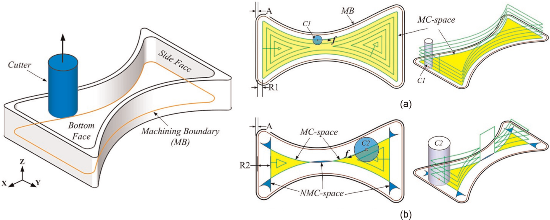
C-space of a pocket when different cutters are used: (a) C-space C1: 1 machining C-space and (b) C-space C2: 2 machining C-space and 5 NMCSs.
There are two fundamental types of undesired machining effects which frequently occur at the MB, that is, overcut and undercut. An industry survey was carried out in several aviation enterprises in China, which concluded the following
Aircraft structural parts have large sizes, complex structures and high machining requirements. Tool-path generation and the preparation work are always time-consuming. The average ratio between the time for tool-path generation and preparation against the real machining time on machine tools is nearly 5:1.
Lack of practical process-plan optimisation methods and the optimisation of process plans often depend on significant manual corrections and interventions during many iterations in using CAPP, CAM and simulation systems. For example, nearly 36% of the time for NC programming is spent on simulation.
Overcut, undercut and cutter collision are three main types of wrong machining effects that should be improved. In particular, overcut and undercut happened at the MB contributing to an average of around 71% undesired machining effects.
In this article, the problem of finding the above-mentioned undesired machining effects is the task of identifying the NMCSs of the machining operation. For each machining operation, the MB is first extracted for offsetting. MB is composed of the area to be machined (machining area (MA)) and the boundary that restricts the cutter movement (restrict boundary (RB)), that is

where MA refers to the MA boundary. Offset rules are decided by the relationship between MA and RB as follows:
Rule 1. If MA and RB are the same as the instance shown in Figure 1, only one of them should be offset and the offset distance is the sum of the cutter radius and machining allowance at RB, so that

where OMB is the abbreviation of offset machining boundary, rbi is the ith boundary of RB and orbi refers to its offset, Rcutter is the radius of the cutter and maRB is the machining allowance of RB.
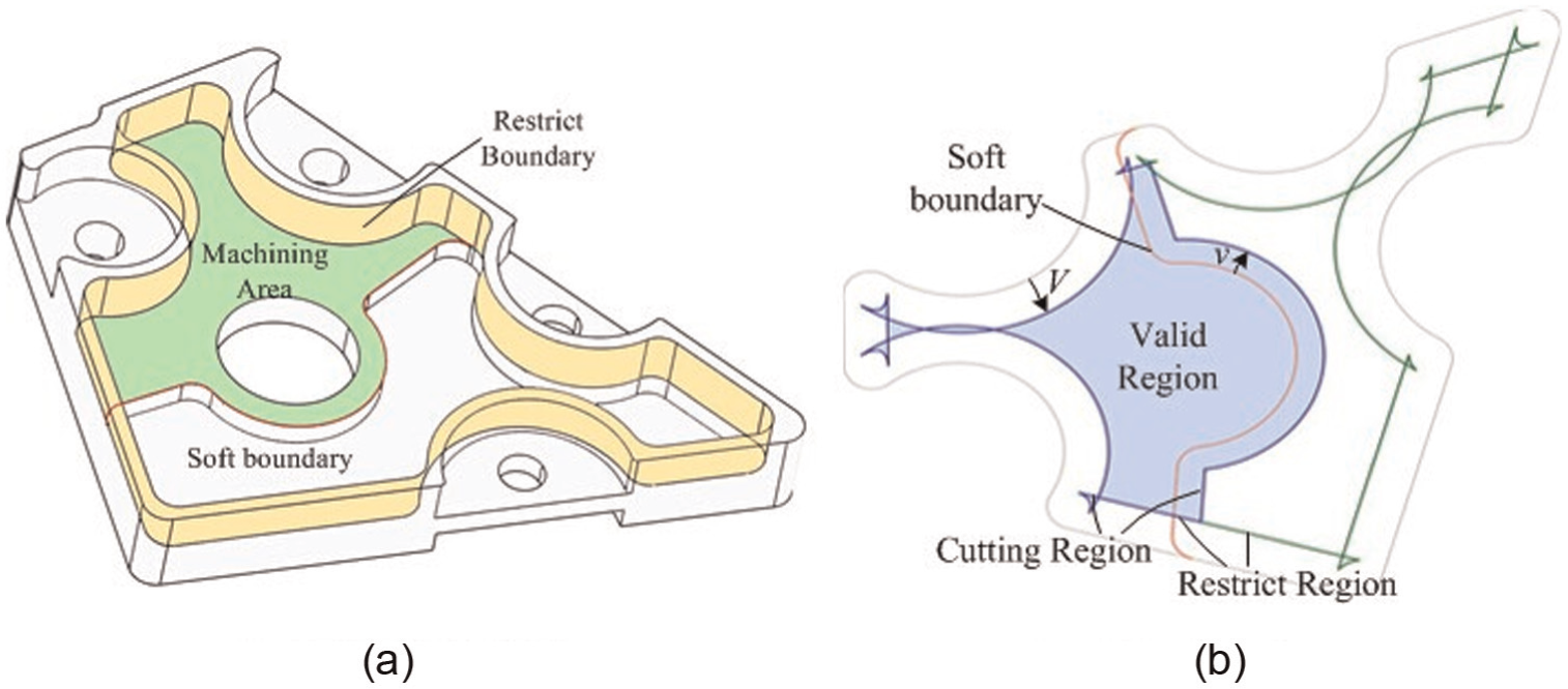
Rule 2. If the boundaries of MA and RB are not equal to each other, RB should be offset as mentioned in Rule 1. Soft boundaries of MA which have no adjacent faces as shown in Figure 2(a) should be offset, but the details are determined by the machining strategy at its soft boundary. The machining strategy to this kind of boundary has three choices corresponding to different cutting movements: ‘Inside’, ‘On’ or ‘Outside’ (see Figure 2(b)). Thus, in this condition, OMB could be represented as

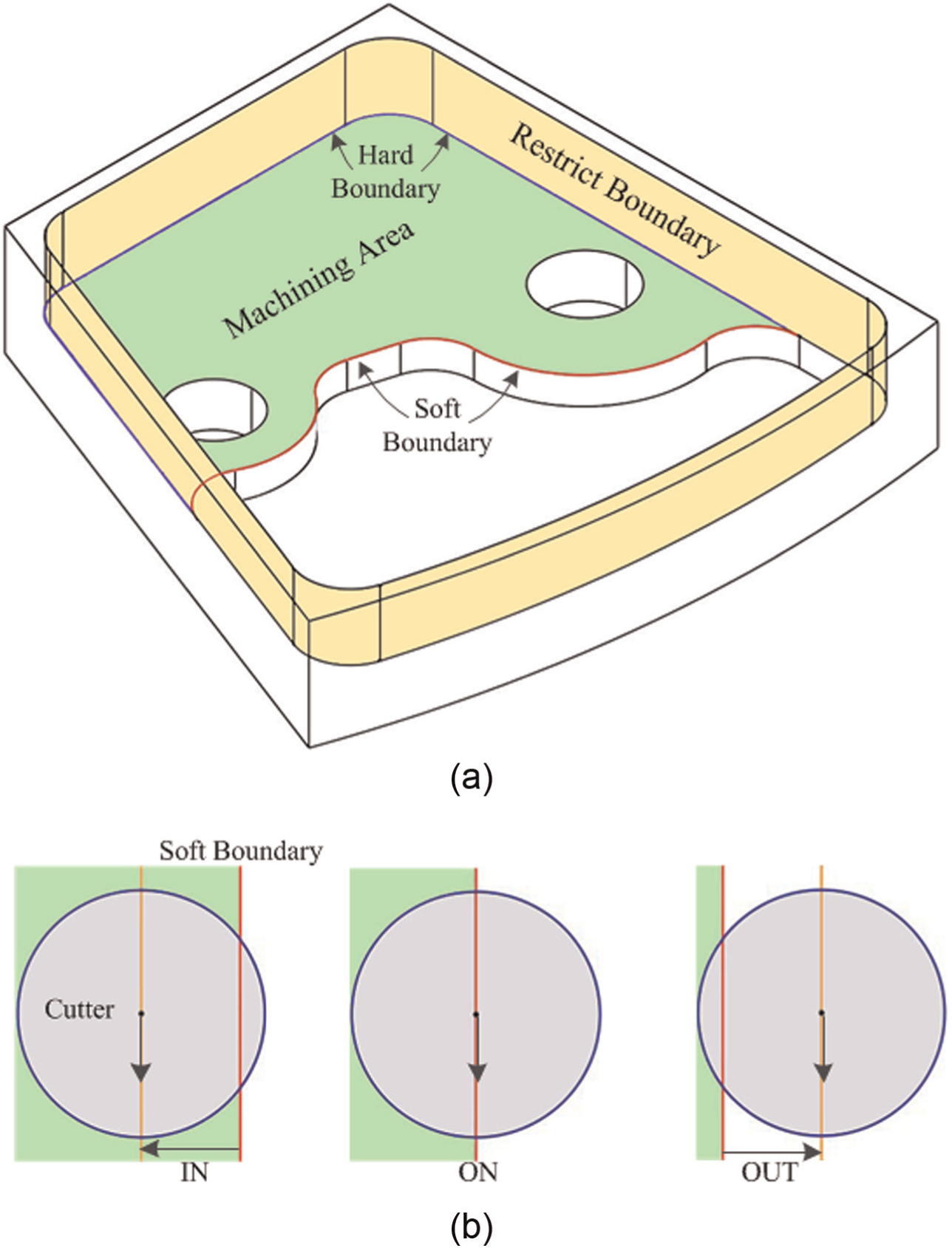
Offset rules for open machining boundary: (a) machining boundary of open layer and (b) three strategies for soft-boundary machining.
where the first half is the same as formula (1), sbj is the jth soft boundary of MA and osbj refers to its offset and vj is the offset value of sbj .
A factor κ is defined to combine formulas (1) and (2)
For each machining operation, NMCSs are the intersection regions in the OMB. Generally, intersections in OMB could be classified into local intersections and global intersections. Local intersections will happen if the radius of the curvature of the local boundary cannot meet the requirement for cutter movements along the boundary. Thus, local intersections always refer to undercut machining effects, like the example in Figure 3. Global intersections are caused by the cutter motion restriction from other boundaries. Global intersections could be further divided into self-global intersections and general-global intersections. The difference between these two categories is about their constituents. The former is the intersection among the offset boundaries of RB, and the latter refers to the intersections between the offset of the soft boundaries of MA and the boundaries of RB. Some cases are given in Figure 3. Self-global intersections correspond to undercut machining effects since most of the tool-path generation algorithms have overcut checking ability. General-global intersections will cause overcut because RB is not considered in calculating the tool path.
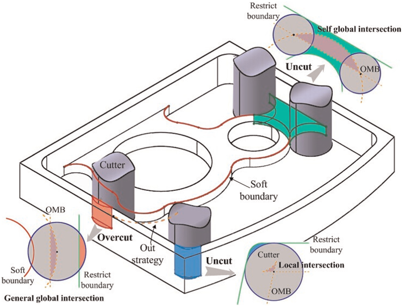
Three typical intersections in the OMB and the corresponding machining effects.
Detection of undesired machining effects
Figure 4 shows the procedures for detecting the intersections in OMB. The global detection stage is to extract the valid detecting portion of OMB. Since cutting motions only take place within MA, to increase the computation efficiency, boundaries outside the overlap of MA and RB will be excluded, as shown in Figure 5. General-global intersections will also be generated in this step. In local-detection process, local intersections will be obtained based on the intersection-detection methodologies mentioned in previous research work.23,24
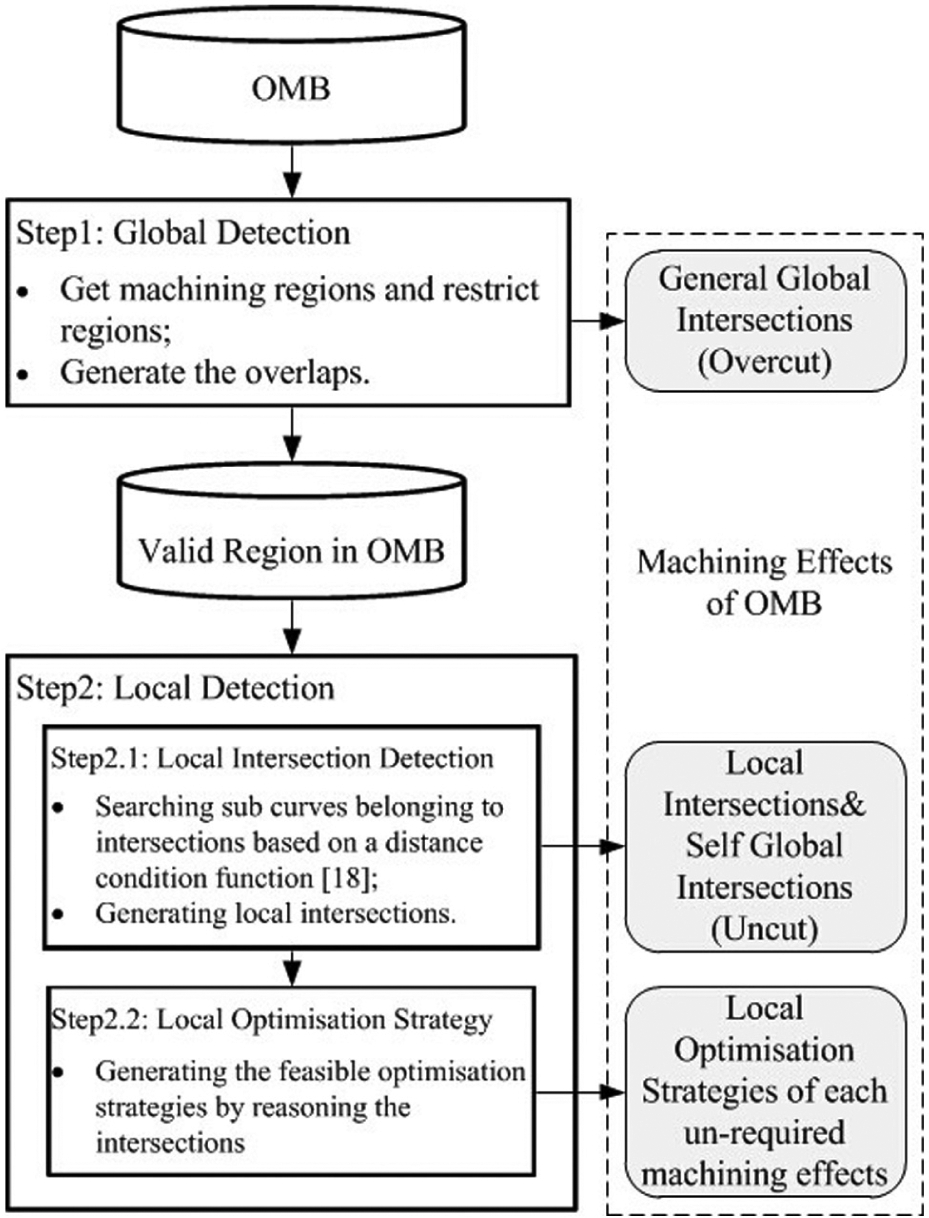
The procedure for detecting intersections in OMB.
Global detection for valid portion and general-global intersections for OMB: (a) a complex structure and (b) valid region of OMB.
OMB is made up of two sets of offset boundaries as represented in formula (3). These boundaries may form some enclosed regions which could be classified into two categories as shown in Figure 5. One is the region that defines the area that should be machined, named as cutting region (CR). The other is the region that restricts the cutter motion during machining for overcut avoidance, which is defined as restrict region (RR). In Rule 1, RR is the same with CR. While in Rule 2, the valid region for intersection detection should be extracted to simplify the calculation of the irrelevant area in RR. The valid region is defined as the overlap area of RR and CR

where ValP(OMB) refers to the valid portion in OMB. As shown in Figure 5, intersections not belonging to the valid portion will not influence the machining effects of this OMB. Regions in CR but not belonging to valid portion means the area where cutter motions are not allowed to avoid overcut to RBs and refer to general-global intersections

where
After getting the valid portion for intersection detection, local detection will be carried out based on it. A distance-based conditional function is utilised to obtain the sub-curves belonging to intersections.23,24 Then, these sub-curves are combined to form the local intersections and self-global intersections based on the classification. As shown in Figure 6, there are three typical local intersections caused by original boundaries with different geometry properties.
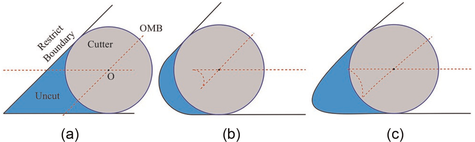
Local intersection types based on the continuity: (a) G0-continuity local intersection, (b) G1-continuity local intersection and (c) G2+-continuity local intersection.
For each undesired machining effect, information of its corresponding C-space like location information and maximum overcut depth could be extracted to determine the optimisation strategy. Cutter optimisation and machining allowance optimisation are two basic strategies to remove the undesired machining effects. Cutter optimisation includes cutter replacement and cutter addition. Cutter replacement means changing the previous cutter with a new cutter which has a smaller radius. This strategy could be implemented for both undercut and overcut machining effects. Cutter addition is to generate a new tool path around the undercut region to remove the redundant material with a smaller cutter. This strategy is only useful for undercut conditions. Machining allowance optimisation aims to reduce the NMCSs by reducing the machining allowance. This way could be accepted to improve both overcut and undercut machining effects. Actually, the final selected optimisation strategy may be the combination of the two basic strategies and should consider more constraints including the cutter change times, total machining time and the cost for global optimisation.
The dynamic feature–based operation planning method
With the machining effects generation method discussed in section ‘Representation of machining effects based on C-space method’, dynamic features could be constructed and the aim of operation planning is to optimise those undesired machining effects. In the authors’ previous research, 2 a representation based on a multiple-layer structure has been discussed and proved to be practical for representing some types of complex structural parts, like aircraft structural parts. In this section, complex structural parts with multiple-layer structures will be applied for dynamic feature construction under a preliminary process plan. Then, an iterative procedure based on this dynamic feature representation will be given for final machining operation generation.
Dynamic feature of complex structural parts with a multiple-layers structure
The process plan for manufacturing a part is usually represented as a list of sequenced machining operations. A machining operation which represents the machining activities performed on the workpiece with the same machine, cutter, setting and method could be seen as a basic carrier of the tool path. As discussed in the previous section, the undesired machining effects of a machining operation could be represented by its NMCSs, thus the dynamic feature could be represented by arranging the NMCSs of the machining operations (Figure 7).
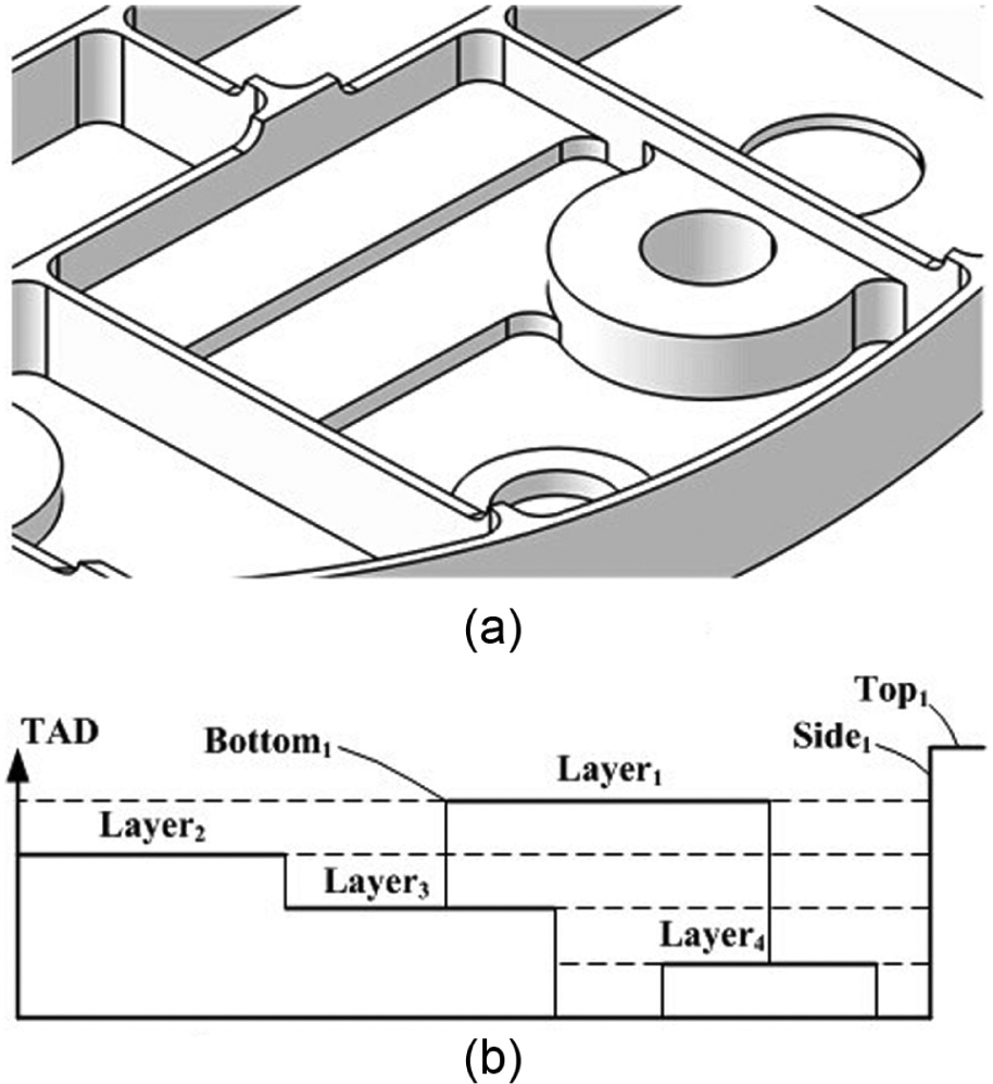
Complex parts’ representation based on multiple-layer structure: (a) an intersecting pocket and (b) layer-based pocket representation.
A layer indicates a single machining volume with bottom, sides and top. 2 In multiple-layer structure, complex parts could be simplified into a list of layers. Generally, the layer that has a larger height to the bottom will be machined preferentially. Therefore, in the multiple-layer representation strategy, the workpiece geometry could be seen as

where m is the number of the layers in the part, i means the machining priority of the layer and smaller i refers to higher machining priority. A layer could be regarded as the basic machining unit. Information about machining steps for the part will be given in the process plan and then be implemented to each layer. In this way, all machining operations for each layer will be generated and classified into each machining step. In a machining step, machining operations are sequenced based on the machining priority defined in formula (6). Thus, the machining operations to a part with a multiple-layer structure could be represented as
where s is the number of the machining steps in the process plan,
To establish the machining effects evolution to the whole machining process, the relations among all the individual NMCSs should be considered. For a multiple-layer structural part, the RB or MA of different layers or different machining steps in the same layer may overlap with others at the plane normal to the tool axis, thus machining effects of this condition are defined as related machining effects. Among related machining effects, machining effects evolution during the whole machining process at the overlap area is very important for the generation of the optimal process plan. A dynamic feature consists of information about process plan, undesired machining effects and machining parameters and could be represented as
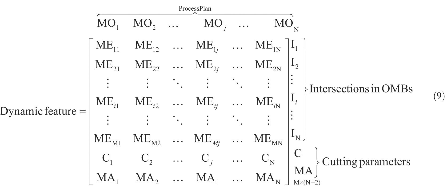
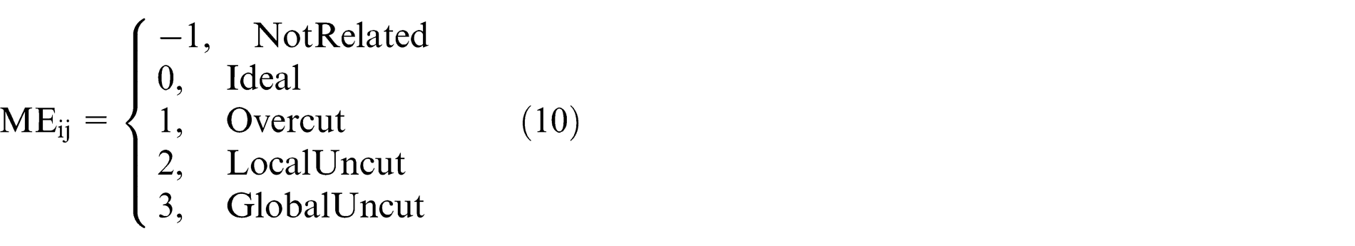
where MO refers to machining operation, I is the intersection in OMB and ME ij is the machining effect of the jth machining operation at the ith intersection. There are five conditions for ME ij
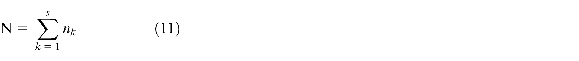
where C refers to cutter and MA is machining allowance at the RB. N is the number of the machining operations which is
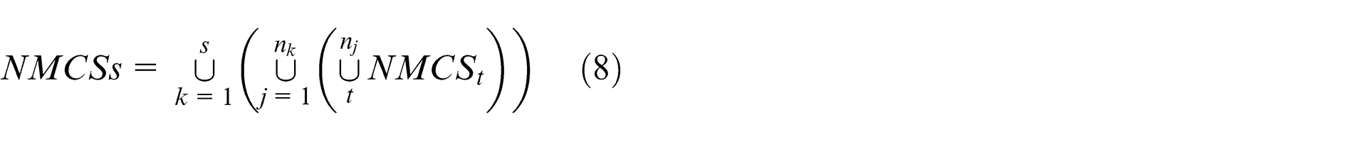
M is the number of NMCSs selected from all machining operations by reasoning about the relationships of their corresponding intersection regions. Three basic relations are defined here as shown in Figure 8, coincident relations referring to the original boundaries of OMBs from different machining operations are the same. For example, the original boundaries of OMBs from both side face-milling and bottom-milling operations for layer 3 are Boundary_Layer_3 in Figure 8. Intended-coincident relations indicate that the original boundaries are not coincident, but their projections to the bottom of the part are the same, such as the Boundary_Layer_3: Edge 003 of layer 3 and Boundary_Layer_2: Edge 003 of layer 2 in Figure 8. NMCSs that satisfy coincident and intended-coincident relations are merged in formula (9). Another relation type is intended-inclusion relations, which mean the projections to the part bottom of the original boundaries satisfy an inclusion relation, such as the Boundary_Layer_3: Edge 001 of layer 3 and Boundary_Layer_2: Edge 001 of layer 2 in Figure 8. Machining parameters including cutter and machining allowance are represented as the last two rows in dynamic feature.
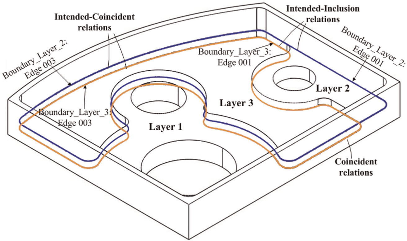
Relations of the original boundaries of different machining operations.
An iterative procedure within dynamic feature for process-plan generation
Optimisation strategies for each wrong machining effect obtained in section ‘Representation of machining effects based on C-space method’ are called local optimisation strategies. Obviously, optimisation for only individual undesired machining effect could not achieve an optimal process plan. MET and VC are defined within dynamic features to reflect the impact of the whole machining process for optimal machining operation plan.
MET refers to the changes of the machining effects at overlaps of machining regions among various operations. MET could be further classified into global machining effects transition (GMET) and local machining effects transition (LMET). If there is an ideal machining effect (ME = 0) in a row of dynamic feature matrix, its process plan could be seen as the reference to optimising the wrong machining effects in this row. This condition is defined as GMET. In LMET conditions, the undercut machining effect in former machining operations could be removed by the latter, thus the undercut machining effect does not need to be handled. GMET could generate the reference process plan for each wrong machining effect, while LMET could decide which wrong machining effects should be handled.
VC refers to the constraints to guarantee the practicability of the optimisation strategies. There are two types of VC, that is, consistency and accessibility. Consistency constraint requires that the optimisation strategies, like cutter replacement and machining allowance reduction for wrong machining effects in an OMB, should be consistent. This means that the final selected optimisation strategy should satisfy all the requirements of the wrong machining effects optimisation in one machining operation because only one cutter and machining allowance are allowed in an individual machining operation. Accessibility constraint is used to restrict the machining-allowance reduction strategy. In overlaps belonging to intended-coincident relations and intended-inclusion relations, the upper layers’ machining allowance should be smaller than that of the lower one since a mutation of cutting depth in the lower layer at the overlap area will be raised and this may cause vibration or damage to the cutter.
A dynamic feature–based operation planning method has been developed as shown in Figure 9. In MET analysis, each row of dynamic features is extracted, and LMET conditions should be first extracted to decide which wrong machining effects should be handled. For those that need to be optimised, GMET analysis will be carried out to search for the current row to find the location where ME = 0 and apply its process plan as the reference optimal process plan for those wrong machining effects. If all the machining effects in this row are wrong machining effects, local optimisation strategies will be applied as the reference optimal process plan.
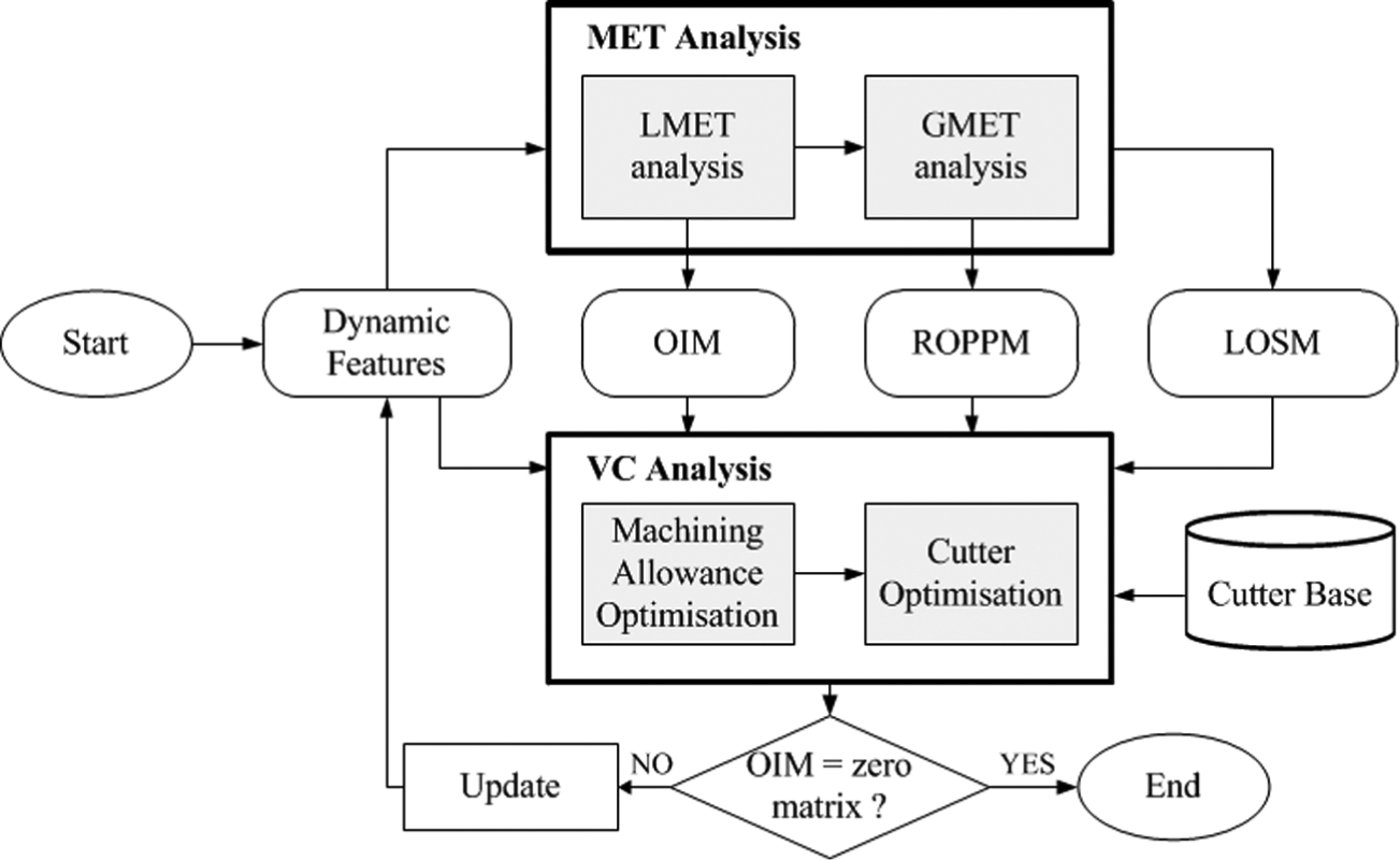
Iterative procedure for optimal process plan based on dynamic features.
The output of MET analysis could be represented as two M × N matrixes. One is the optimisation index matrix (OIM) which is defined to mark the wrong machining effects that need to be optimised. There are two possible values for each OIM ij , that is, 0 and 1, where 0 means that the machining effect remains without any treatment and 1 means that the machining effect should be optimised
where ME ij = (2, 3) ∈LMET means the machining effect is local uncut or global uncut where a local machining effect transition is satisfied. Another matrix which is used to represent the reference optimal process plan for undesired machining effects is called the reference optimal process-plan matrix (ROPPM), that is
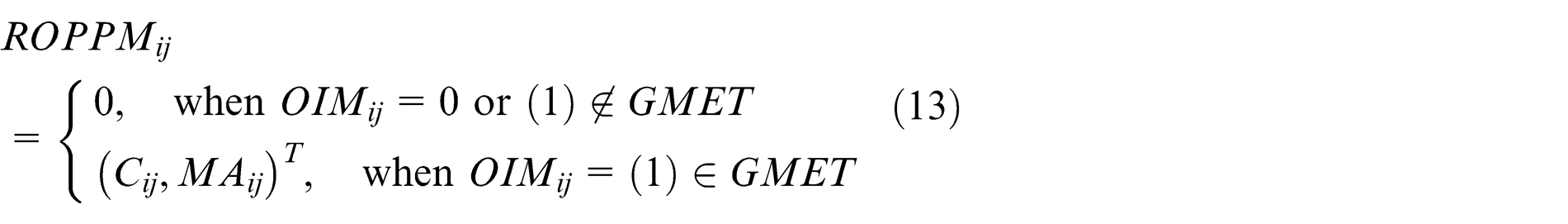
where
In VC analysis, each column of the current dynamic features is analysed to determine the optimisation strategy for the corresponding machining operation. The analysis starts from the final machining step to the first since the LMET conditions might be updated by the optimisation of the following machining steps. In a machining step, the first machining operation is selected as the start, because in accessibility constraints, the machining allowance of the previous OMB is the restriction to the current one. To satisfy the consistency constraint, an optimisation strategy decision is made to cover all the wrong machining effects. Obviously, MET analysis is based on the rows of dynamic features and VC analysis is column oriented. In this part, local optimisation strategies for each individual wrong machining effect in dynamic features are applied and represented as an M × N matrix named local optimisation strategies matrix (LOSM). LOSMij
has a structure similar to ROPPMij
which is
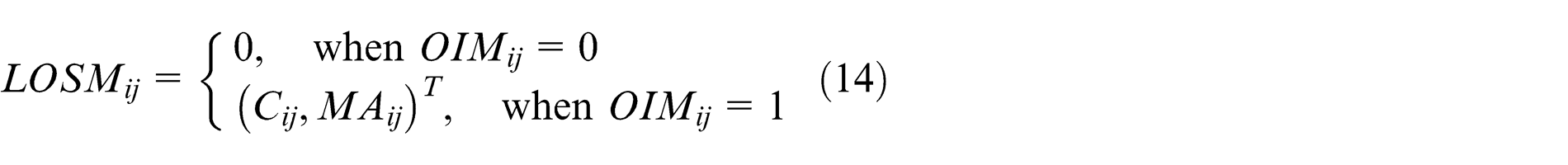
In ROPPM, the reference optimal process plan exists as instances such as {Cutter: R = r; Machining Allowance: MA = ma} which comes from the process plan used in ideal machining effects. But in LOSM, the local optimisation strategies are feasible optimal scope like {Cutter Replace: R ≤ r}. Moreover, LOSM is generated at the machining effect detection stage, while ROPPM is obtained at MET analysis stage.
The first step of the optimisation strategy decision in VC analysis is machining allowance optimisation strategy planning since these kinds of strategies do not change the cutter or add other operations. The aim of this step is to decide whether a machining allowance optimisation strategy with the current cutter could satisfy the requirement of all the wrong machining effects. This step should consider the accessibility constraint. If only machining allowance optimisation could not reach an ideal process plan, it will come to cutter optimisation stage. In this stage, each LOSMij of the jth column is extracted and the minimal boundary rmin ∣LOSMij of the feasible cutter space is calculated. The new cutter selection space is (0, rmin ∣LOSMij ]. Cutter instances in ROPPMij of the same column are then obtained to match with (0, rmin ∣LOSMij ]. Once the cutter radius belongs to this interval, the cutter is regarded as a feasible choice. If the feasible cutter selection has multiple choices, the one with a larger diameter is chosen since larger cutter could increase machining efficiency. If there is no feasible cutter instance in ROPPMij , the new cutter selection searching space should be changed to the company’s cutter database to find a proper cutter which belongs to (0, rmin ∣LOSMij ]. Once the new cutter is determined, the machining allowance should be decided based on this new cutter.
Once the optimisation strategy for the beginning column is generated, dynamic features should be updated and MET analysis should be executed again for OIM, ROPPM and LOSM updating. The iteration will continue until OIM equals to a zero matrix and the last two rows of current dynamic features could be applied as the optimised process plan. With this iterative procedure, machining effects as well as their evolution during the whole machining process keep updating and are applied for getting the optimal process plan.
System development and application
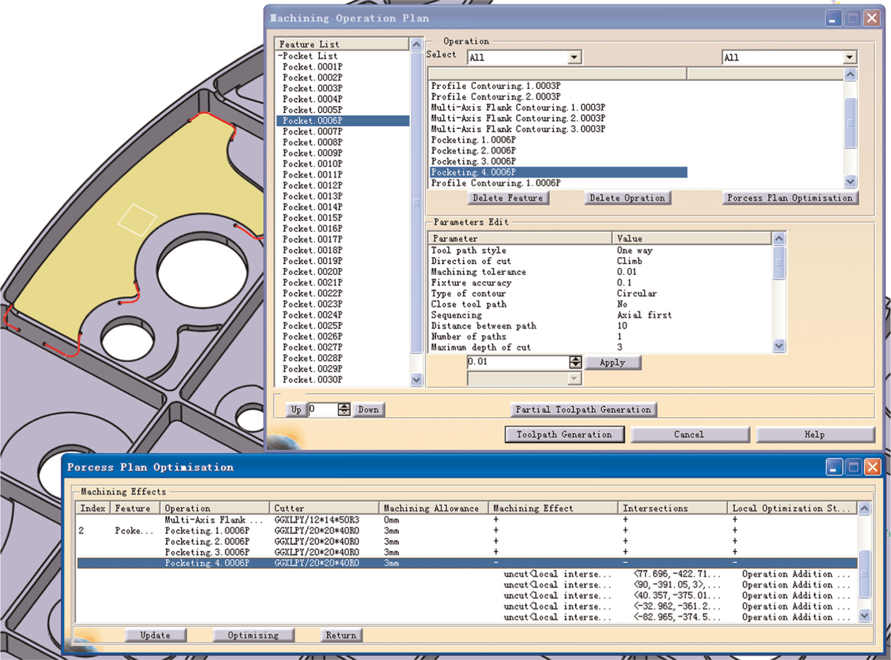
This section will use an aircraft structural part as an example for machining process planning. The dynamic feature–based process-planning method was tested in a feature-based NC programming system developed in the CAM application of CATIA V5 R18 named FBM_NUAA. The system consists of 4 main modules: global information management module, feature extraction module, process-planning module and tool-path generation module as shown in Figure 10.
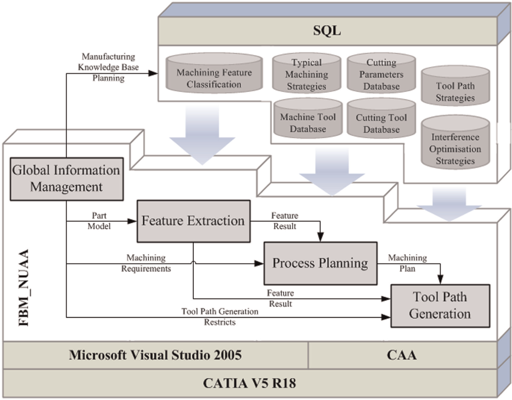
System structure of FBM_NUAA.
In the global information management module, global information about a part’s structure, material and machining requirements can be input and edited. The linkage between the system and the manufacturing knowledge database like typical machining strategies and cutting parameters are also handled in this module. Feature extraction module is used to get machining features in the part model. The output is the machining feature information and is saved in an XML file format. This module has both automatic and manual feature extraction functions.
The input of the process-planning module is feature information and machining requirements; the process planning is based on the machining databases linked to the global information management module. The output of process-planning module has two levels, one is about the global process plan containing selected machine tool, fixture and clamping strategy. The second is the process plan for machining the feature consisting of a machining operation list. Machining operation list contains the set-up plan, cutters, parameters and machining sequence. The tool-path generation module generates the tool path using the process plan from the previous module. The method proposed above is used in the process-planning module.
The feature extraction method used in FBM_NUAA is proposed by Li et al. 25 The part model in Figure 11 was tested in the system. Feature extraction result is shown in Table 1.
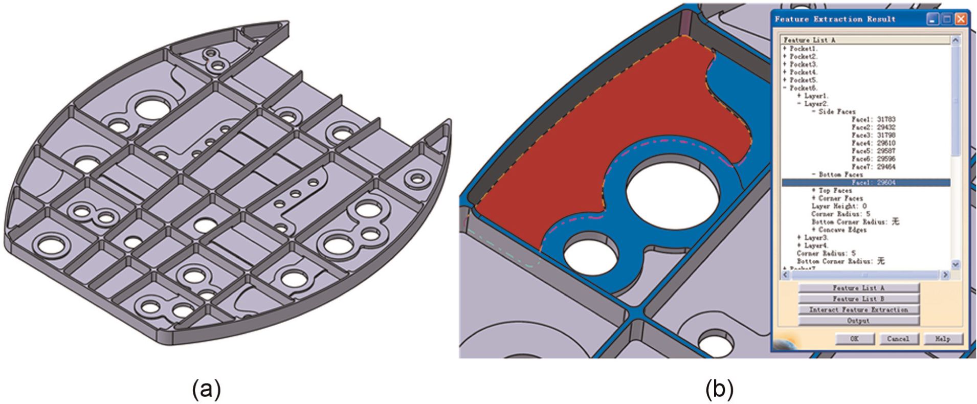
Feature extraction of the test part in FBM_NUAA system: (a) test part model and (b) feature extraction result.
Results of the test part in Figure 11.

This structural part is mainly made up of a list of pockets with multiple-layer structure. In the feature extraction module of FBM_NUAA system, these feature extraction results of these pockets are organised by layers and the details of each layer could also be obtained as shown in Figure 11.
The dynamic feature–based operation planning method proposed above was applied in the process-planning module of FBM_NUAA system; a preliminary process plan was first extracted from a knowledge base. To express the advantages of the proposed method, another two traditional process-planning methods were selected for comparison. The test work was carried out using the same computer. The computer CPU is Intel Core i7-3770K and the memory is 8 GB. The test CAM system is CATIA V5 R18.
One test method is the traditional feature–based process-planning method using static feature information model as the representation of the part. In this method, a list of feasible typical process plans were generated based on matching the feature geometry and the machining requirements – choosing one from them as the preliminary process plan and then mapping it to each feature. Eventually, machining operations were created based on machining regions and the recommended cutting parameters including cutter, feed speed, cutting width and depth. This method could be seen as the basic procedures of the current feature-based process-planning methods. Actually, the proposed method applies the same way to generate the preliminary machining operations for dynamic features construction. As shown in Table 2, although the static feature-based method has the best computation efficiency, it requires much more time for simulation and human interaction. With this method, the detailed feature geometry was not considered. As a result, there were usually various undesired machining effects. The most time-consuming task was the simulation for acquiring those undesired machining effects. In this test, a senior engineer with 6 years of work experience was chosen to carry out the optimisation of the preliminary machining operations.
Comparisons of the three test methods.
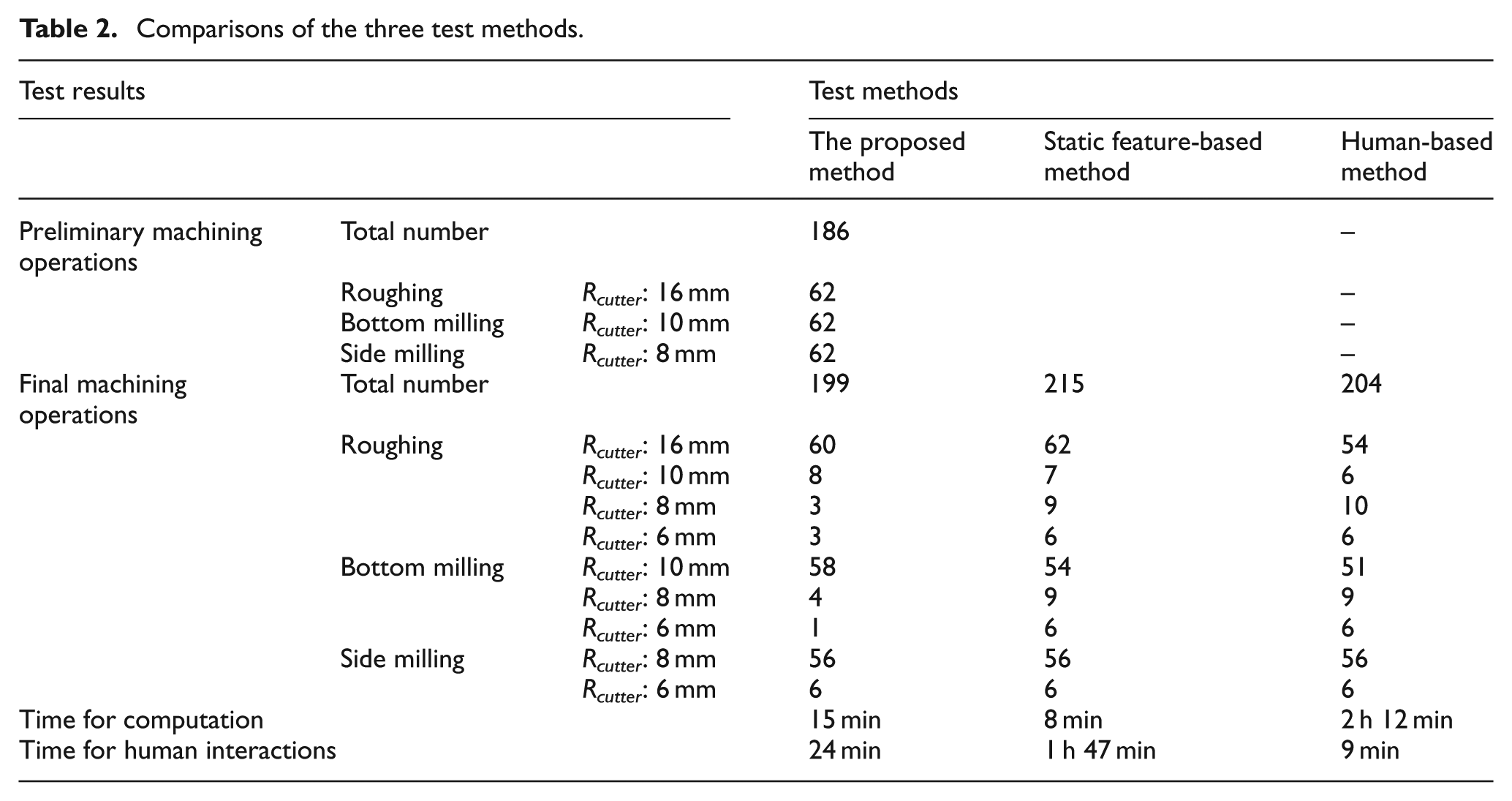
Another method is more human-based, which is widely used in real-life manufacturing. All process-planning work is done by a human engineer assisted by commercial CAD/CAM systems. The result of this method is decided by the engineer’s experience and ability. Another senior engineer with 9 years of work experience in process preparation in aircraft structural parts NC machining was selected for human-based machining operation planning on CATIA V5 R18. As shown in Table 2, human-based method required a long period for getting the machining operation plan. But the result was more accurate than the static feature–based method since the engineer handled each individual machining operation manually.
For the comparison of the static feature–based and the proposed method, the machining operations for pocket features generated based on the preliminary machining process plan are shown in Table 2. After process planning, the final machining operations generated by the three methods are also given. Only undercut machining effects exist in this case, and the number of preliminary machining operations containing this kind of undesired machining effects in roughing, bottom milling and side milling are 22, 15 and 6, respectively. In static feature-based and human-based methods, the undesired machining effects were handled individually by replacing the cutter or adding new machining operations with smaller cutters. However, in the proposed method, machining effects as well as their transitions among these machining operations could be obtained, as shown in Figure 12, and considered for operation planning. Some undercut machining effects could be left without treatment and removed by the following operations. As a result, less machining operations are required and larger cutters could be used as much as possible to improve machining efficiency.
Machining effects within a dynamic feature.
Conclusion
With the study into the manufacturing of aircraft structural parts, a dynamic feature–based machining operation planning method was proposed in this article to address the requirement of complex structural parts NC machining. A dynamic feature consists of information about the machining effects of the feature between various operations carried out during the whole manufacturing process. NMCSs are constructed to obtain the undesired machining effects like undercut and overcut. During process planning, dynamic features based on a preliminary process plan are first established. Then, an iterative procedure for adjusting the preliminary machining operations is put forward by integrating dynamic feature information updated with METs and VCs. Finally, the method has proved to be feasible by testing an aircraft structural part in a feature-based NC programming system. For further research, the authors will expand dynamic feature–based machining operation planning method to other machining applications such as die cavity machining by embedding holder-collision avoidance and including method for computing multi-axis machining solutions.
Footnotes
Declaration of conflicting interests
The authors declare that there is no conflict of interest.
Funding
The results presented in this article are generated from the projects funded by the National Science and Technology Major Project of China (2012ZX04010041).