
Abstract
This article presents a new method for automatic tool selection using discrete techniques based on Poisson’s equations for computer numerical control lathe-mill machine operations and rapid tooling. This method proposes to generate linear triangulation in the boundary of the piece and tool, after creating moves of tool around the piece to detect intersection; thus, this creates directional field through mesh allowing selecting the type of tool in agreement with the size, magnitude and direction of tool. The proposed methodology has been implemented in computer-aided manufacturing software, in different types for two-dimensional, two and a half–dimensional and three-dimensional pieces computer-aided design, showing the correct selection of the cutting tools. The novelty of this article is the use of discrete technique applying Poisson’s equation; the piece thus checks the intersection between the piece and tool when the tool is moving.
Keywords
Introduction
Nowadays, the demand for better productivity with high quality is increasing. The computer numerical control (CNC) machines at present and in the next generation should take into account numerous variables that affect the machining process, for example, tool materials, total error compensation, concepts of autonomous manufacturing, process condition monitoring, to develop commercial computer-aided manufacturing (CAM), the development of a system capable of recognizing complex features, cutting fluids and tool selection, among others. 1 Certain contributions on these topics are the investigations conducted by Abou-El-Hossein 2 and Eladawi et al. 3 Automatic tool selection in turning and milling operation is one of the most important steps in process planning; moreover, at present, CAM software transfers this task to the worker who does it based on his or her own experience, ability and knowledge. In machining processes, commonly tool selection is made by a human operator; if this is incorrect, it can produce errors in workpiece dimensional, such as possible crashes, and consequently rejecting the piece. In this sense, researchers have developed for tool selection in milling processes such as in the work presented by Bouaziz and Zghal. 1 Ahmad et al. 4 conducted a study based on analytical models using optimization algorithm only for prismatic pockets machining. In the same way, Ramaswami et al. 5 applied dynamic programming to determine the optimal tools for machining only polygonal pockets. Another approach for tool selection is proposed by Lim et al. 6 who developed an experimental algorithm based on mathematical Boolean.
On the other hand, in the case of tool selection problems in CNC machines, Oral and Cakir 7 and Edalew et al. 8 developed an approach of tool selection based on mathematical methods and data composed of years of heuristic knowledge. The use of dynamic SQL and criteria of tool select from database to recognize characteristics of the piece shape in .DXF format is presented by You et al. 9 Finally, the case of tool sequence problems by Im and Walczyk, 10 the cutting condition effects as roughness presented by Sarma et al., 11 the prediction of cutting conditions by Gadelmawla et al. 12 and path generation are included for milling CNC machines by Eladawi et al. 3
The novelty of this research is a new method based on triangulation intersection approach from Poisson’s equation applied to automatic selection of the tool CNC mill-lathe machine, showing an easy way to simulate pieces, eliminating the designer subjective decisions, to reduce tool selection mistakes, to make the selection process and to design faster, and hence, it does not require a priori knowledge in operations of milling and turning.
Methodology
The application of triangulation and rapid tooling (RT) 10 to determine the intersection using Poisson’s equations to solve manufacturing problems is a new approach in the literature. Automatic tool selection is an important cutting parameter to reduce machining time, errors, human interaction, costs and better product quality. 13 Sutheebanjard and Premchaiswadi 14 developed new methodologies by the widely use of CNC machines in the industry. The development of diamond shape of cutting tools for CNC lathe and ball nose for CNC mill or machining center to perform operations is varied; using this research data handbook and catalogs of tool, manufacturers used to select the proper tool for turning and milling operations.
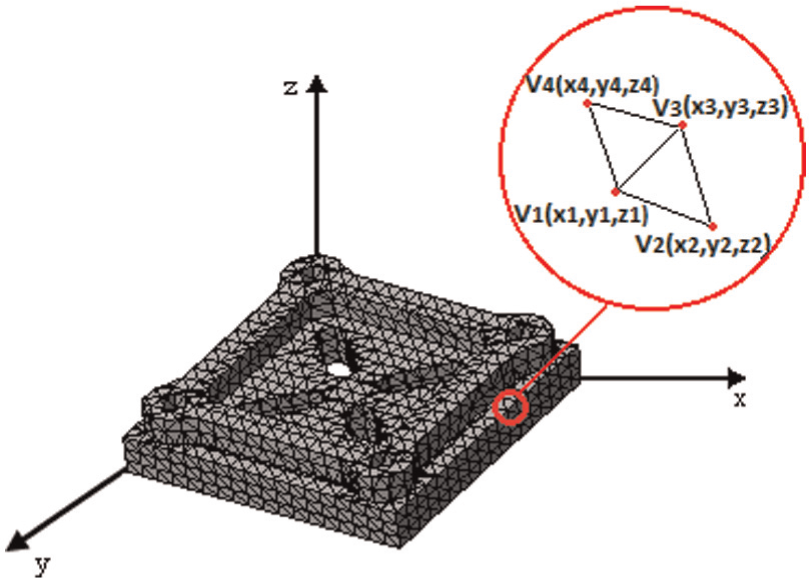
In this article, the original file is two-dimensional (2D) or three-dimensional (3D) model taken from computer-aided design (CAD) software, and it validates in CAM–computer-aided engineering (CAE) systems whether graphics, designs and simulates, respectively, facilitate the user to do the tasks.14–16 This piece is transformed to a .DXF file format by the easy and low cost in terms of computational work.17,18 After this, a method of discretization (triangulation) is applied on the piece and tool using Poisson’s equations to obtain the mesh, based on the Galerkin scheme by Sulaiman et al. 19 Many algorithms for computing Delaunay triangulations in 2D rely on fast operations for detecting when a point is within a triangle; however, it is necessary to modify the method.20–22 After obtaining features of the mesh such as the gradient to find the slope, edge detect for the position of the gradient vector is applied. Finally, a structural element (tool discretized) with the shape of the cutting is displaced through workspace with the length values of the boundary piece and the lengths of the cutting tool from right to left and from bottom to top creating roughing paths for 2D models and zig-zag, and zig-zag constant with contour for 3D model, changing the dimensions of the tool, if there is an intersection 23 between the model and the tool when it is moving (see Figure 1). The advantages of this algorithm are eliminates the designer subject decisions, reduces tool select mistakes, is relatively simple and fast to be implemented, does not require a priori knowledge and the designed tool selection can be integrated within a CAD/CAM system to use in other applications.
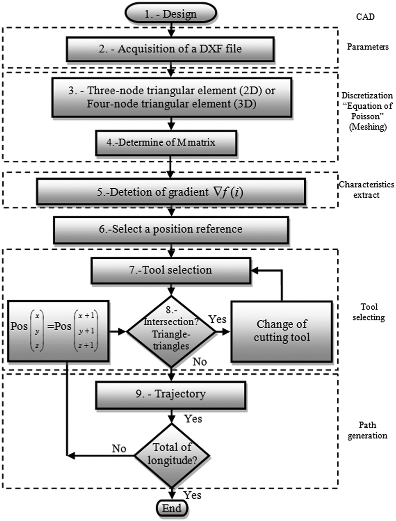
General diagram.
Step 1: design original of piece CAD
In this step, the original file (2D, 2.5D and 3D models) is designed or taken from CAD; in order to analyze the method, two pieces are used: the first piece is a mold and the second piece is a pawn of chess.
Step 2: acquisition of .DXF file
The original design (Figure 2(a)) is obtained from CAD; after this, upper profile model is converted to .DXF file. 24 This file contains information about the drawing, definitions of items and the entities that make up each block as shown in Figure 2(b).
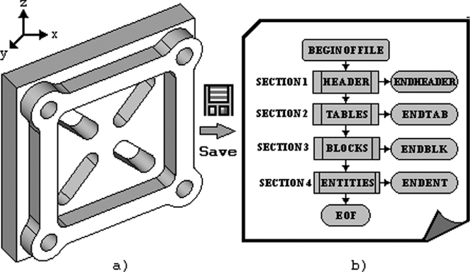
Original files: (a) design from CAD and (b) .DXF file.
Step 3: three-node triangular elements for 2D piece and four-node triangular elements for 3D piece
The following step is the discretization
25
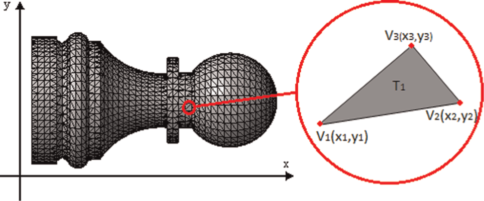
using three-node triangular element in 2D elements as shown in Figure 3. This is also known as linear triangular element and is simpler than others;
26
it has three nodes at the vertices of the triangle with

where

where

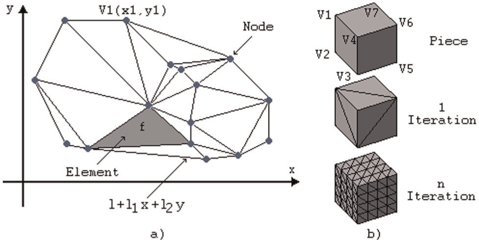
Implementation of three-node triangular element: (a) discretization in two-dimensional elements and (b) discretization in three-dimensional elements.
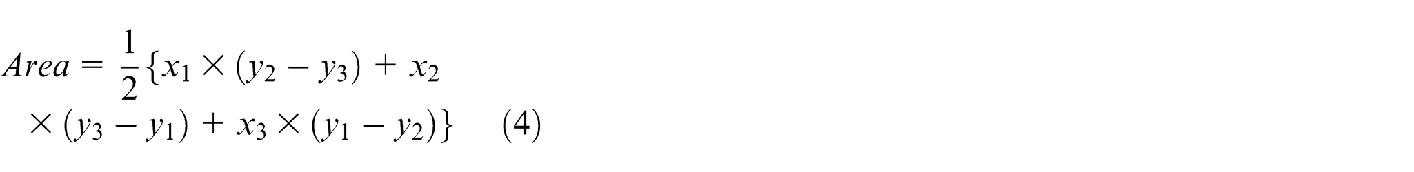
The Area corresponding is obtained by equation (4)
The processes of computation of the element nodal sequence must be in the same direction for every element. Substituting equation (3) into equation (1) produces equation (5)

In the above,
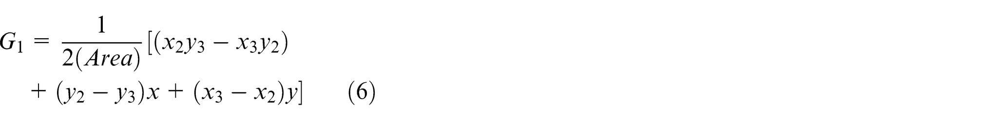
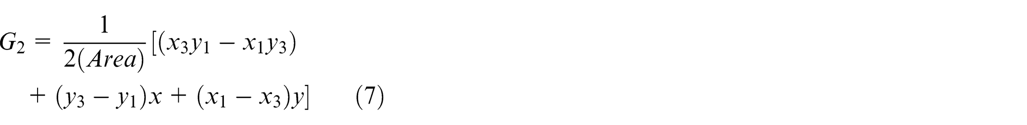
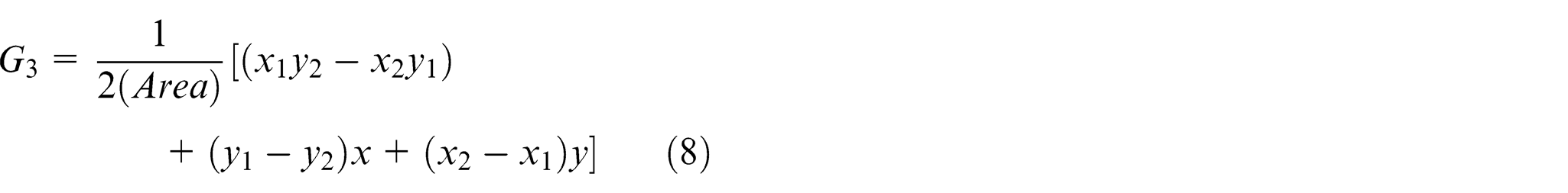
Figure 4 shows an example of mesh discretization, where
Example of mesh discretization.
As seen in the discretization of Figure 4, the conditional point of vertices and the actual curved boundary are approximated by a piecewise linear boundary. In 3D analysis the Poisson’s equation, 25 can be extended directly into equation (9)

where

Implementation of four-node triangular element (discretization) in three-dimensional elements.
Otherwise, the interpolation function is linear in each axis evaluated at the nodal points, to obtain equation (11)

Since

Step 4: determination of M matrix of triangulation for 2D and 3D
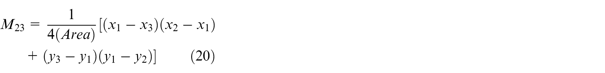
The standard triangulation of the piece may be refined using linear triangular elements. Other alternatives are using higher-order elements of polynomial expressions 19 or Delaunay.20,21 For a linear element of 2D triangular piece shown in Figure 4, the matrix element is calculated as

where

whose entries are displayed as follows


where

Here

Converting equation (9) and substituting the shape functions

where

Finally, Figure 6 shows the discretization (meshing) results of the piece, with element width of 3.3, minimum angle between triangles of 175°, approximation factors (between 0 and 1) of 0.001 and number of smoothing iterations of 500. Figure 7 shows the discretization of the piece with element width of 1.1, minimum angle between triangles of 175°, approximation factors (between 0 and 1) of 0.001 and number of smoothing iterations of 500.
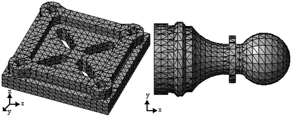
Discretization of the piece, width of 3.3 and angle of 175°.
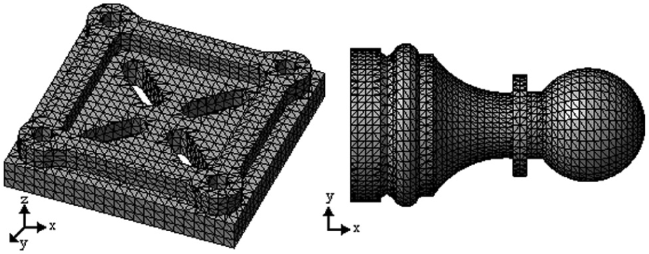
Discretization of the piece, width of 1.1 and angle of 175°.
Step 5: detection of gradient of the piece in the triangles
Determination of gradient of the piece in the triangles is obtained by applying the normal vector at a point of the triangulation obtained from the discretization; the gradient gives the position and direction of the piece in the workspace.27,28 The normal vector at a point

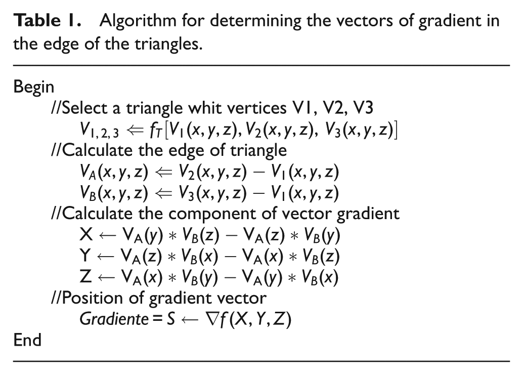
Figure 8 shows the directional vectors of gradient in the edge of the piece for 2D and directional vectors of gradient in the edge of the triangles for 3D, for CNC mill-lathe, and the algorithm is shown in Table 1.
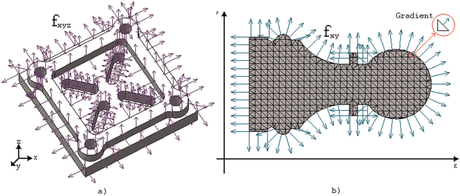
Directional vectors (gradient) of the triangles: (a) piece in 3D and (b) piece in 2D.
Algorithm for determining the vectors of gradient in the edge of the triangles.
Step 6: tool selection
The cutting tool is in a turret and during cutting operation is necessary consider other crash with machine tool body, the workspace with the structural element of the turret was implemented, however, lengths of all machines have different dimensions, in this article, own software let the user input of data for reconstruction of tools for a special example. The direction of the gradient in the edge allows selecting the type, size and the angle of the tool, and the common types of cutting tools used in turning operations are left (L), right (R), neuter (N), knife (K), drilling (D) and holder (H) for external and internal works, and the common cutting tool (structural element) used is shown in Table 2.
Common cutting tool (structural element) used.
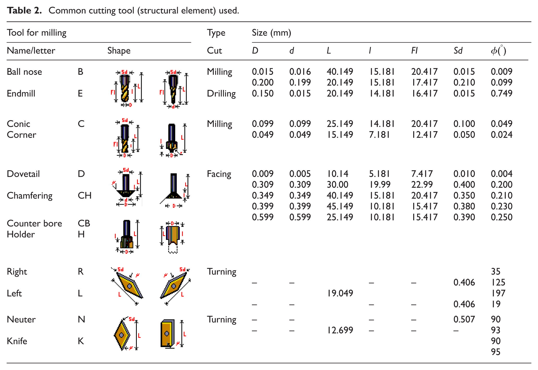
The library of the cutting tool is generated from manuals and tools stored in the warehouse; these data (diameter, length, angle and nose radius of the tool) are introduced into the software; to identify the most suitable tool, the decision is given in Table 2.
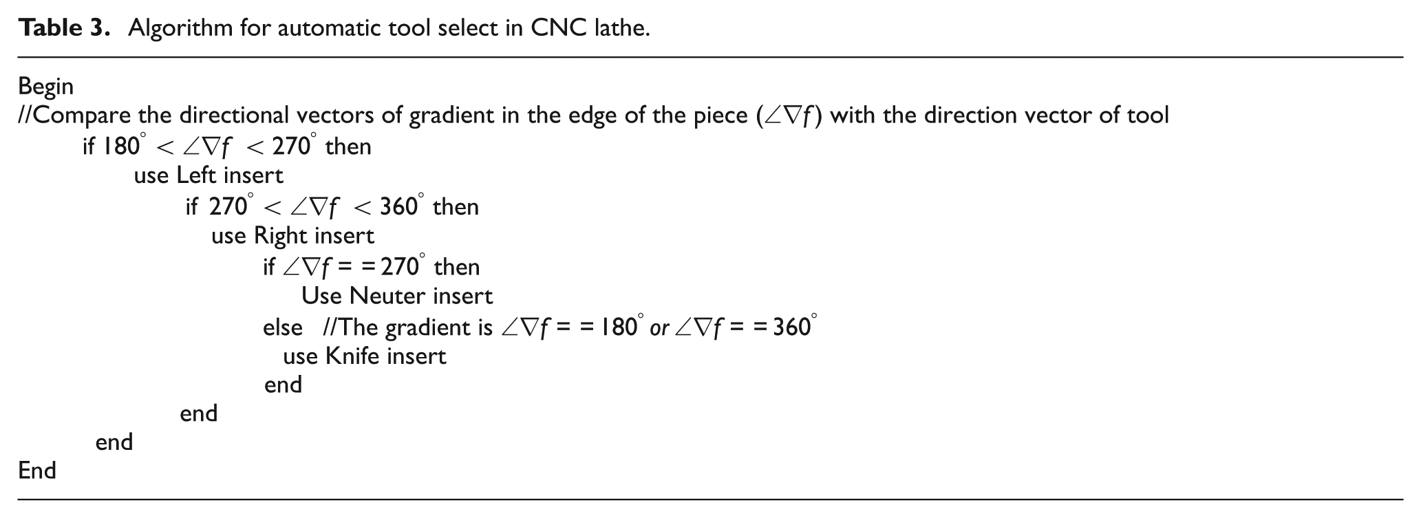
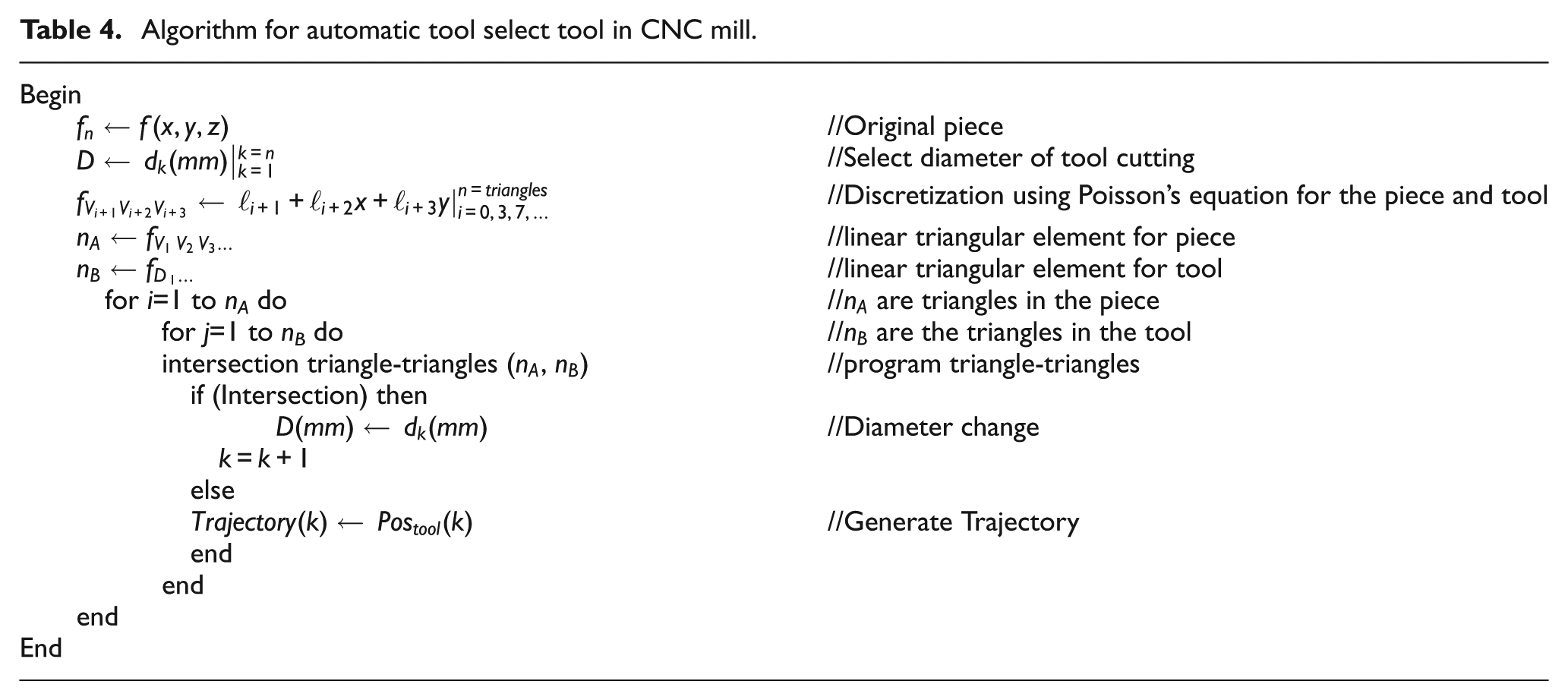
The common types of cutting tools used in milling operations are shown in Table 1; the tool is moved through the edge in a way such that the cornering of piece, which represents the cutting tool, coincides with each triangle of the edge. If at any triangle of the edge there is an intersection between the piece and tool (Figure 6(a)), the tool is not correct and another tool is tried (Figure 6(b)); to identify the most suitable tool, the decision is given in Table 3. The procedure of intersection of the tool with piece is checked using triangle–triangle intersection techniques with the own software as shown in Table 4.
Algorithm for automatic tool select in CNC lathe.
Algorithm for automatic tool select tool in CNC mill.
Step 7: triangle–triangle intersection
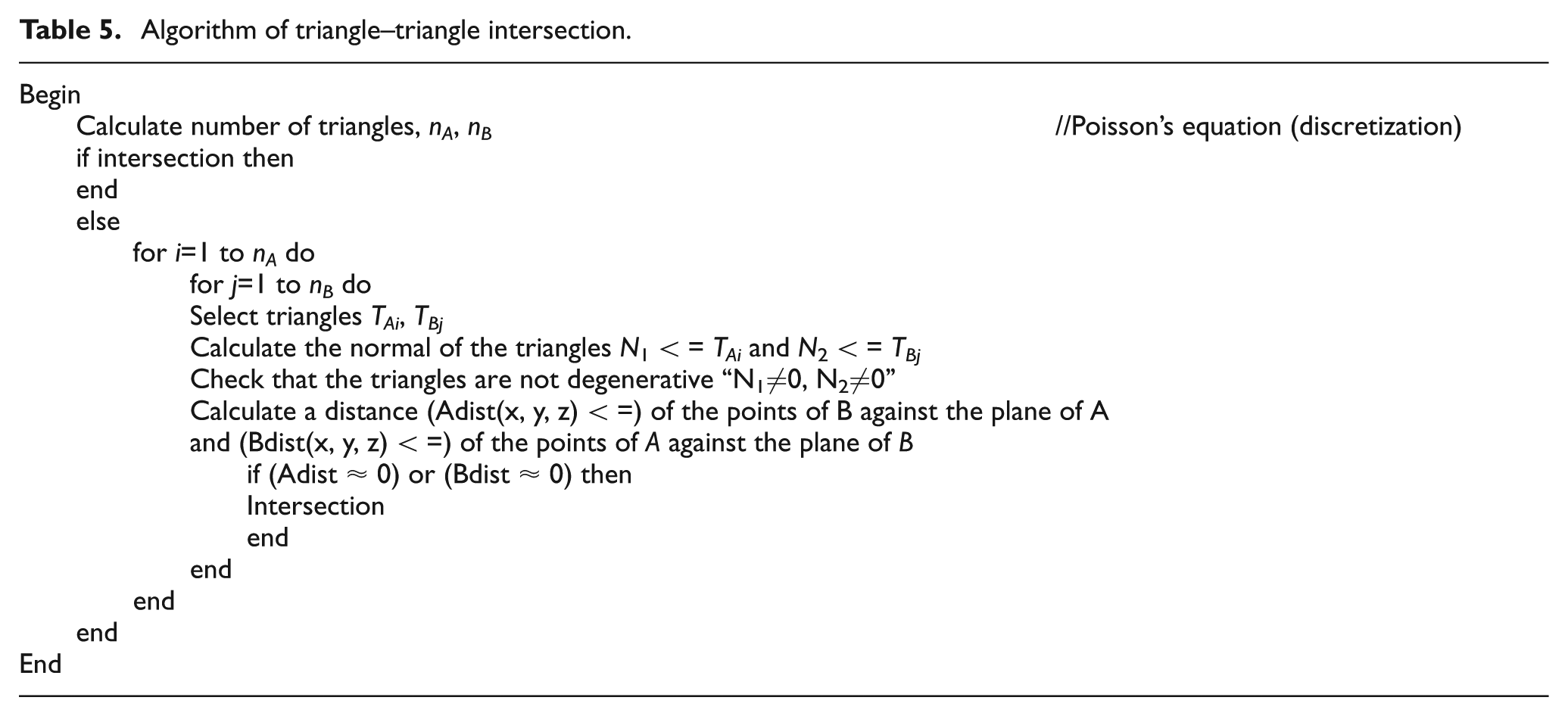
In this step, the workpiece and the cutting tool were already discretized (triangulation) according to desired dimensions (angle and size of the triangles) as shown in Figure 9. As a result of the previous steps, the data of input are the number of triangles of the cutting tool and the piece to be machined (nA , nB ); with the fixed piece and moving tool, a triangle of tool is selected and compared with each triangle of the piece; the comparison allows to determine the normal for these two triangles and check that they are not degenerative, and finally, the distances of each triangle are compared with respect to a reference framework; if these distances are the same or coincide, then there is intersection and the dimensions of the tool are changed; otherwise, other triangles are selected, if the comparison ends and there is no intersection, then the tool selection is correct, and this process is shown in Table 5.
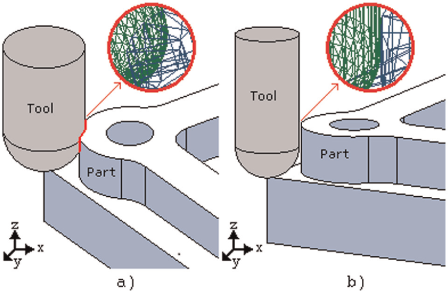
Tool select, (a) incorrect tool and (b) correct tool.
Algorithm of triangle–triangle intersection.
Step 8: tool path generation strategy
The methods of trajectories generation are zig (one way), zig-zag (two ways), zig with contour, zig-zag with contour, follow-periphery, trochoidal and profile.
29
In this article, the zig and zig with contour are used because of easy generation of trajectories. The tool path is obtained with an algorithm (zig), and a tool (structural element) with the shape of the cutting tool is displaced through all workspaces from right to left and finally from bottom to top in the
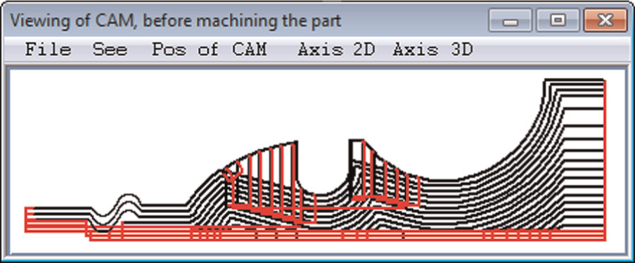
Tool path generation strategy, zig with contour.
Results and discussion
With the aim to validate the proposed methodology, two pieces were processed to automatically select the correct tool. Eight tools are available for machining, one piece for 3D (milling) and four for 2D (turning), including operations such as external rough cutting, internal rough and thread for turning and pocket, thread, helicoidal, extrusion, profile and section, fillet and chamfer for rough mill and finish mill.
The first piece is shown in Figure 11. The selection of the cutting tools is presented in Table 6, and the cutting path for rough cutting is shown in Figure 11(a) and (b), and Table 6 shows the results of the selected tools by applying the proposed method.
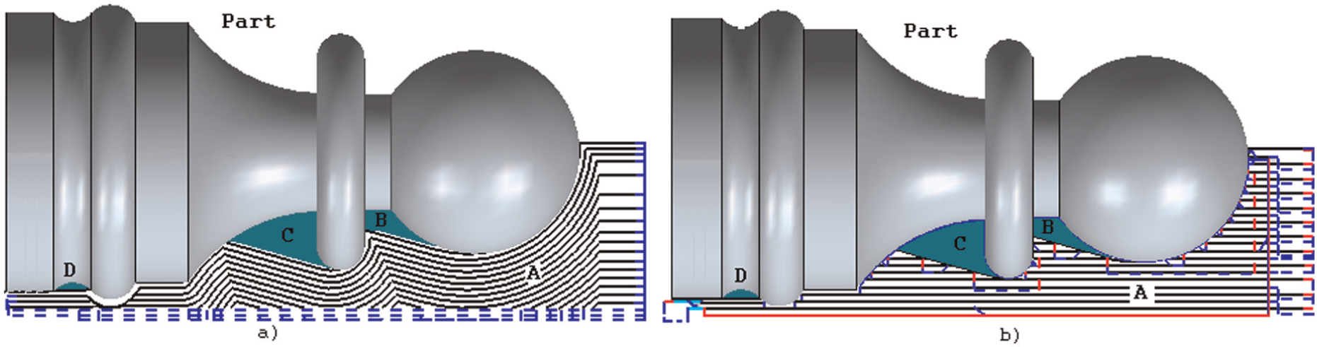
Tool selection (final piece): (a) rough turn (zig with contour) and (b) rough turn (zig-zag).
Selected inserts for piece of Figure 11.
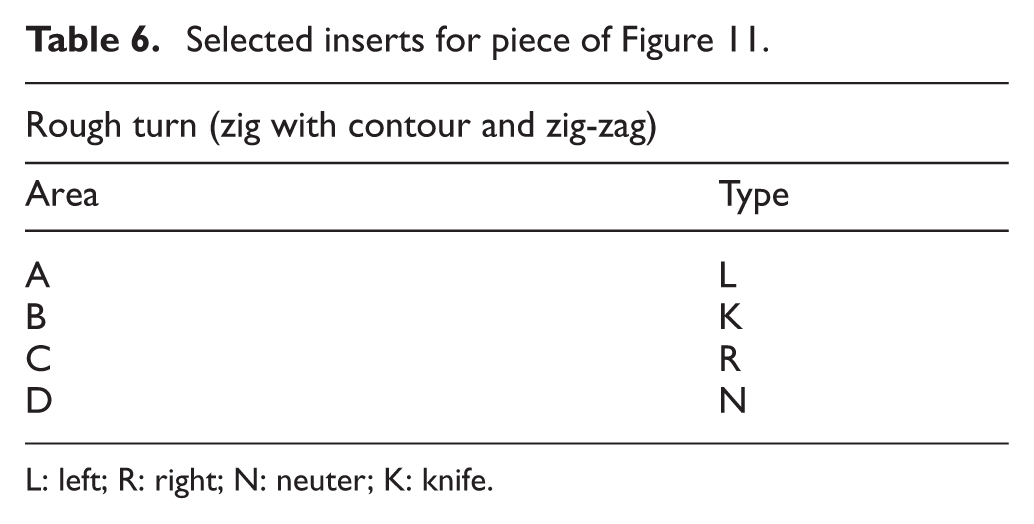
L: left; R: right; N: neuter; K: knife.
The second piece is shown in Figure 12; the result of the selected tool by the proposed method is presented in Table 7, and the cutting path for spiral zig with contour is shown in Figure 12(a) and for constant Z in Figure 12(b). The developed software is shown in Figure 13. It was developed in Microsoft Visual C++ 2010 and tested with 2D, 2.5D and 3D pieces generated in any CAD software.
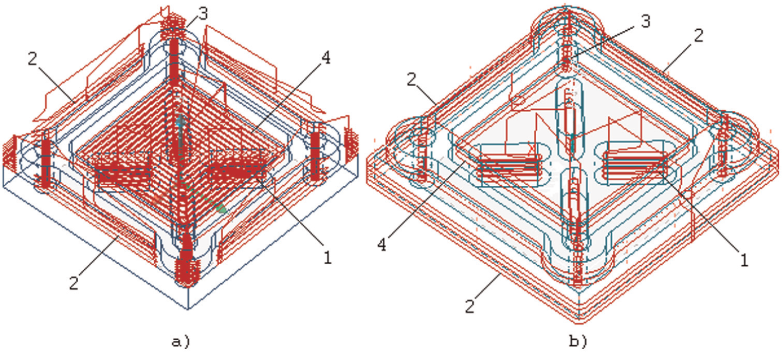
Tool selection using rough mill (final piece): (a) spiral zig with contour and (b) constant Z.
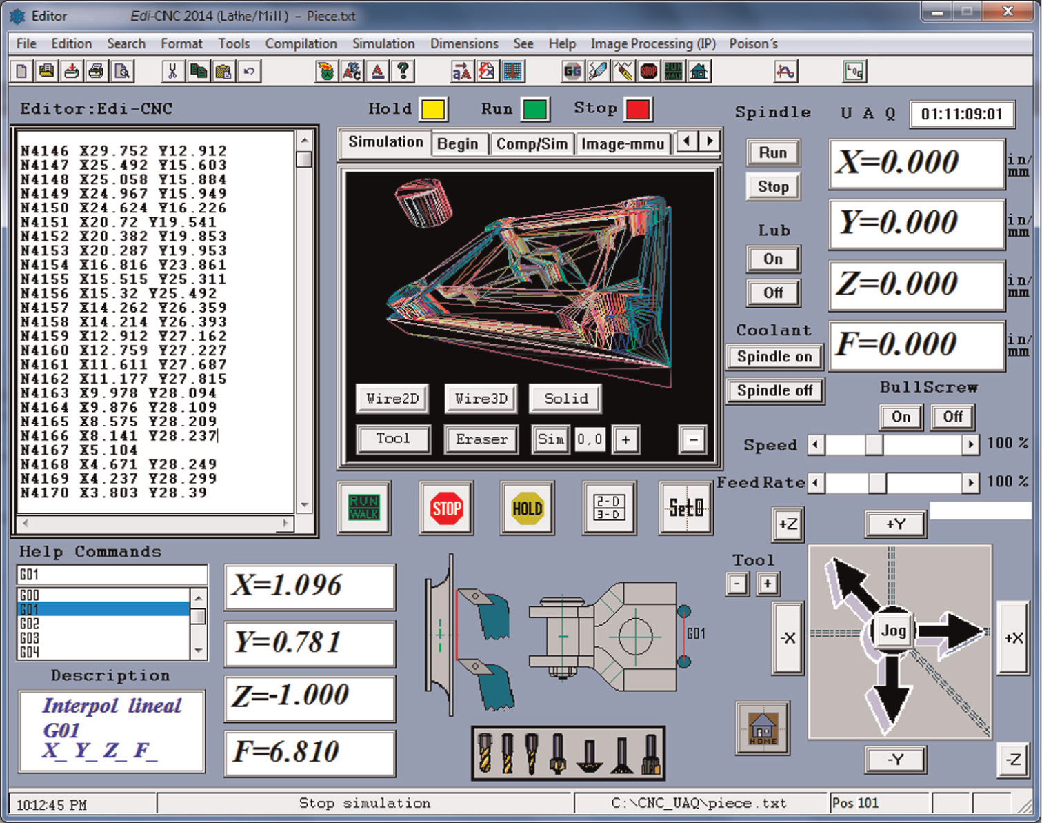
Final software for automatic tool selection.
Selected inserts for piece of Figure 12.
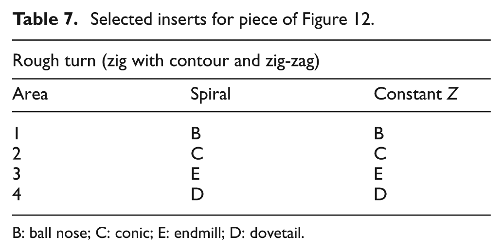
B: ball nose; C: conic; E: endmill; D: dovetail.
Conclusion
In this work, a new method for automatic tool selection using triangulation intersection approach from Poisson’s equation applied to automatic selection for CNC mill-lathe machines has been presented. This method is relatively simple and fast to be implemented. The proposed methodology has been implemented in pieces generated by CAD software and exported to .DXF file. Also, a higher resolution transformation of CAD file to .DXF file can be utilized to improve both the resolution and accuracy of this system. The methodology was performed and applied to two mechanical pieces in order to find the cutting tools and the respective paths. Results show that the methodology can select the correct tool.
Footnotes
Declaration of conflicting interests
The authors declare that there is no conflict of interest.
Funding
The authors wish to acknowledge the financial support of UAQ and the financial support by CONACYT (grant number 209333).