
Abstract
High-speed grinding experiments were conducted on a nickel-based superalloy Inconel718 with the monolayer brazed wheel containing monocrystalline cubic boron nitride grains and polycrystalline cubic boron nitride grains. Comparative investigation on the wear behavior and self-sharpening phenomenon of polycrystalline cubic boron nitride and monocrystalline cubic boron nitride grains was carried out based on the fractal analysis. The results obtained indicate that the wear process of the monocrystalline cubic boron nitride grain cutting edges is, in order, attritious wear → large fracture → micro fracture → large fracture → attritious wear, while that of the polycrystalline cubic boron nitride grain cutting edges is micro fracture → attritious wear → micro fracture. Micro fracture of polycrystalline cubic boron nitride grain occurs easily in the particular zone where large impact load is formed due to the first contact between the grain cutting edges and the workpiece material. The fractal dimension of monocrystalline cubic boron nitride wheel is 2.040–2.047, while that of the polycrystalline cubic boron nitride wheel is 2.049–2.054, which indicates that the polycrystalline cubic boron nitride grain cutting edges are finer than that of the monocrystalline cubic boron nitride counterparts. Compared to monocrystalline cubic boron nitride grains, better performance, that is, smaller radial wheel wear, lower grinding force and forces ratio, is obtained for polycrystalline cubic boron nitride grains due to micro fracture behavior and self-sharpening phenomenon in high-speed grinding.
Keywords
Introduction
High-speed grinding with cubic boron nitride (cBN) grains has broad application prospects in machining difficult-to-cut materials, that is, nickel-based superalloy and titanium alloy in aerospace industry.1–7 However, the representative conventional monocrystalline cBN (McBN) grains are always accompanied with the inherent shortcoming of anisotropy, which makes it difficult to self-sharpen by means of grain micro fracture. For example, Malkin and colleagues8,9 have discovered that the major wear patterns of the McBN grains in the monolayer electroplated wheel were attritious wear, grain large fracture and grain pullout under the mechanical and thermal shock loads. Similar results were also found for vitrified and brazed cBN (or diamond) wheels during grinding.10–12
The polycrystalline cBN (PcBN) grains are composed of microcrystalline cBN grains and AlN binder material under high temperature and high pressure. 13 Compared to the McBN grains, the particular microstructure of the PcBN grains ensures their self-sharpening potential due to the predominance of micro fracture mode during grinding. Moreover, the size of the micro fracture region in PcBN grains is significantly smaller than that in McBN grains, which could give lower tool wear rate and therefore higher grinding ratio.
Different from the multilayer vitrified cBN wheels, the brazed cBN wheels contain monolayer abrasive grains held on the tool matrix by the brazing filler bond, which ensures firm joining of the connecting layer to the grains.14,15 Premature grain pullout, therefore, was totally absent even under the large grinding load. 16 However, similar to the monolayer electroplated cBN wheels, the topography of the monolayer brazed cBN wheels is not periodically restored by truing or dressing. 17 Under such condition, tool wear is of a particular concern with monolayer brazed cBN wheels due to the limited amount of available grains and the need for a sufficiently long tool life. As a result, the wear behavior, that is, attritious wear and grain fracture, also has a significant influence on the working surface topography of the brazed cBN wheels, causing changes in the grinding performance throughout the tool life. 18 Little quantitative analysis has been conducted on the wear behavior of the brazed abrasive grains until now. Previous research was concentrated on the qualitative analysis of the morphology and mechanism of the cutting edges of the worn grains during grinding.
Fractal theory is a good choice for characterizing the surface topography, which has been widely applied in geomorphology, physics and other fields.19–25 A feasibility study has been conducted by Ichida et al. 26 to quantitatively evaluate the morphology change in the cutting edges of the McBN grains by means of fractal analysis. Meanwhile, Miao et al. 27 established a model to investigate the wear behavior of the PcBN grains based on fractal theory. Some instructive results have been obtained. However, previous work was merely carried out in the conventional wheel speed of around 30 m/s. The evolution of the wear behavior and the self-sharpening phenomenon of the McBN and PcBN grains in the whole grinding process were not discussed.
In this article, the monolayer brazed wheel containing McBN and PcBN grains was fabricated, with which high-speed grinding experiment was conducted on a nickel-based superalloy. The wear behavior and self-sharpening phenomenon of the McBN and PcBN grains versus the accumulated volume of removal material were analyzed quantitatively. The influence of the tool self-sharpening phenomenon on the radial wheel wear, grinding force and forces ratio was discussed.
Experimental material and details
Fabrication of monolayer brazed grinding wheel
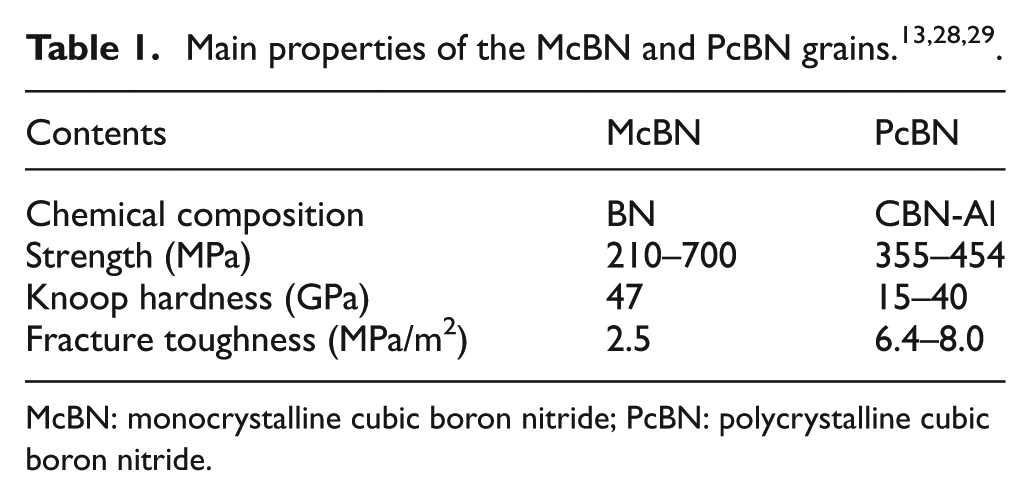
The size of both the McBN and PcBN grains was 40/50 mesh (355–425 μm in diameter), as shown in Figure 1. The main properties of the McBN and PcBN grain are listed in Table 1.13,28,29 The particular wheel structure containing a groove was designed in order to braze McBN and PcBN grains into the different parts of one grinding wheel (Figure 2). The external diameter of the wheel was 400 mm and the inner diameter was 127 mm. The pre-alloyed (Cu80Sn20)90Ti10 (wt%) powders were utilized as the connecting layer of the grinding wheel to join the abrasive grains and the metallic wheel matrix at the brazing temperature of 900 °C. The brazing method and mechanism were reported in our previous work. 30 The grain distribution pattern with the row distance of 1.2 mm is demonstrated in Figure 2(c), which ensures the sufficient space to store chips.
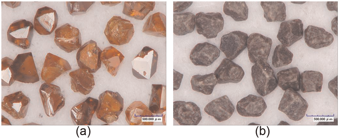
Morphology of (a) McBN grains and (b) PcBN grains.
McBN: monocrystalline cubic boron nitride; PcBN: polycrystalline cubic boron nitride.
Monolayer brazed grinding wheels with McBN and PcBN grains: (a) monolayer brazed wheel, (b) brazed McBN (left) and PcBN (right) grains and (c) grain distribution patterns.
Details of grinding experiments
Straight surface grinding experiments were performed on an instrument BLOHM PROFIMAT MT-408 grinding machine while applying a 5% solution of a commercial soluble water-based coolant with a pressure of 15 MPa. The maximum rotational speed of the spindle was 8000 r/min and the output power was 45 kW. The ground material was a nickel-based superalloy Inconel718, a typical difficult-to-cut material. During grinding, the part with McBN grains and that with PcBN grains of the particular wheel worked.
Nowadays, high-speed grinding of difficult-to-cut materials is a popular and interesting topic.31–33 Based on the potential industrial application and the research status of high-speed grinding technology, grinding experiments were carried out in the up mode with the fixed grinding parameters, namely, wheel speed vs of 120 m/s (spindle speed of 5732 r/min), workpiece infeed speed vw of 1676 mm/min and depth of cut ap of 10 μm in the present investigation. Under such condition, the maximum undeformed chip thickness agmax is 0.58 μm and the material removal rate (MRR) is about 0.28 mm3/(mm s). It is noted that the MRR is defined as the product of the workpiece infeed speed and the depth of cut during grinding. The maximum undeformed chip thickness agmax is calculated according to the following equation34,35

where Nd is the active cutting point density (3.46 mm−2 in this study), C = 4tgθ (θ is a half of the angle of abrasive tip) is a constant correlated with the angle of the grain tip, ds is the diameter of the grinding wheel, vs is the wheel speed and ap is the depth of cut.
Grinding experiments were terminated at the end of the useful working life of the brazed McBN wheel, which was readily identified by a sudden increase in the grinding force and destruction of the grain layer. The grinding forces were measured using a quart piezoelectric-type dynamometer (Kistler 9272), attached with 5070A10100 multichannel charge amplifier and computer data acquisition software.
Measurement and analysis of wear behavior of grain cutting edges
In order to keep a trace of the wear behavior and self-sharpening phenomenon of the grinding wheel, 30 McBN grains and 30 PcBN grains, respectively, were selected randomly from eight symmetrical regions of the monolayer brazed grinding wheel. Three-dimensional (3D) optical microscopy modeled Hirox KH-7700 was periodically applied to capture the grain topography in the different wear stage during grinding. All the images and corresponding data were obtained under the identical condition, including the magnification level (350×), the light source and the microscope parameter settings.
Particularly, not only the reconstruction model of the 3D grain topography profiles but also the calculation method of the fractal dimension of the grain cutting edges has been reported in the previous work (see Appendices 1 and 2). In this article, the authors would directly apply the method to investigate the wear behavior and self-sharpening phenomenon of the McBN and PcBN grains in high-speed grinding.
Experimental results and discussion
Morphology schematics and fractal dimension of typical grain cutting edges
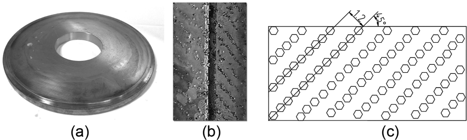
In order to understand the wear behavior of the abrasive grains in the brazed wheels during high-speed grinding, Figure 3 schematically displays the possible wear patterns of the grain cutting edges: original shape, attritious wear, large fracture and micro fracture. According to Figure 3(a), the difference in the microstructure of the two types of grains, McBN and PcBN, is obvious. The McBN grain is a monocrystalline particle (brown region), while the PcBN grain is a polycrystalline particle containing microcrystalline cBN (brown region) and AlN binder (white region). The yellow region surrounding the grain is the connecting layer of the Cu-Sn-Ti alloy. When the grain endures the ductile attritious wear (Figure 3(b)), the cutting edges of the grain would become dull by attrition and develop a wear flat. The flat surface is always ineffective for penetrating into the workpiece surface and therefore results in undesirable high grinding force and low grinding efficiency. 36 If the grinding load exceeds a critical value, the grain may fracture so that new sharp cutting edges are produced continuously in the grinding process, which is called as grain self-sharpening phenomenon. 37 The reason is that fracture grain tends to have rough irregular surface and significantly restricts wheel dulling. However, it is not suitable for a grain to self-sharpen by the large fracture (Figure 3(c)) because drastic grain wear is induced during grinding. Self-sharpening due to micro fracture (Figure 3(d)) is generally appropriate for effective grinding because it offers small grain wear and good grinding performance.
Wear patterns of grain cutting edges: (a) original shape, (b) attritious wear, (c) large fracture and (d) micro fracture.
Particularly, under the effect of the external grinding load, the PcBN grains fracture due to the breakage of the brittle AlN material which bonds the microcrystalline cBN grain, while the McBN grains fracture by means of the cleavage fracture of the blocky-shaped cubo-octahedral single crystal particle with the anisotropic property and undesirable crystallographic defects inside the grain. 36
Statistical analysis of the fractal dimension of the cutting edges was conducted for the sample grains. Figure 4 displays the average value of the fractal dimension for different wear patterns of the grain cutting edges. In general, different wear pattern corresponds to different average value of the fractal dimension. Furthermore, the fractal dimension value of PcBN grain cutting edges is always larger than that of the McBN counterparts, which indicates that the more complicated microstructure is formed on the tip of the worn PcBN grain. For instance, the average value of the fractal dimension for the McBN grain cutting edges formed due to attritious wear on the tip of the grain is 2.042, while that for the PcBN grain is 2.047. When the McBN grain cutting edges endure micro fracture, the average value of the fractal dimension is 2.046, while at this time, it is 2.051 for the PcBN grain cutting edges. In particular, the average fractal dimension is 2.043 for the cutting edges of the worn McBN grain due to large fracture. However, large fracture seldom takes place for the PcBN grain cutting edges, and the corresponding fractal dimension is not obtained here.
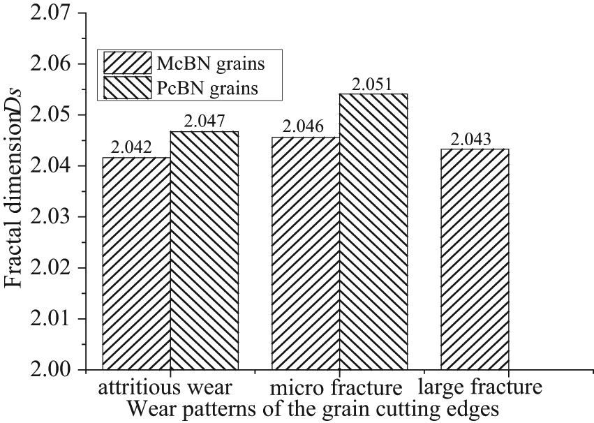
Relationship between fractal dimension and wear patterns of the grain cutting edges.
Wear behavior of the McBN and PcBN grain cutting edges
Figure 5 displays some typical sequential optical images, 3D profiles and counter maps of a McBN grain with an increase of the accumulated volume of the material removed per unit grinding width V′ in high-speed grinding. Generally, the grain cutting edges changed their shape in different forms with the advance of the wear behavior. As seen in Figure 5(a), a ductile attritious wear flat was formed in the central part (white region) on the top surface of the grain cutting edges when the stock removal V′ was 100 mm3/mm. Furthermore, the wear flat surface became larger with the increasing stock removal, as displayed in the comparison among Figures 5(a)–(d). For example, the attritious wear flat area at V′ = 400 and 600 mm3/mm was significantly larger than that at V′ = 100 mm3/mm. When the accumulated volume of the material removed V′ reached 1100 mm3/mm, the largest value of the attritious wear flat area of the grain cutting edges was obtained. Meanwhile, some fracture behavior also happened at the top surface of the grain. Under such condition, although the grain cutting edges may become dull because of the attritious wear, they could reproduce and maintain their sharpness due to the fracture occurred repeatedly on the top surface of the grain. 37 That is to say, the self-sharpening phenomenon of the McBN grain cutting edges was exhibited due to grain micro fracture. It should be noted that, compared to the micro fracture behavior, the attritious wear and large fracture took the leading effects in the wear behavior and grinding performance of the McBN grain cutting edges.
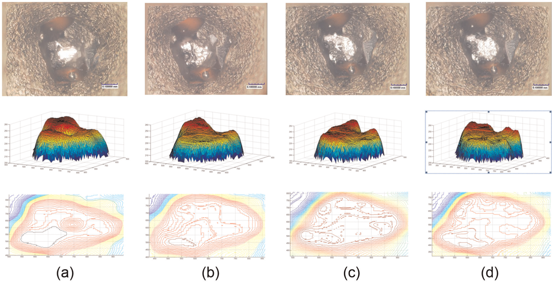
Surface morphology, 3D profiles and counter maps of typical worn McBN grain cutting edges: (a) V′ = 100 mm3/mm, (b) V′ = 400 mm3/mm, (c) V′ = 600 mm3/mm and (d) V′ = 1100 mm3/mm.
The morphology of the PcBN grain cutting edges was also detected sequentially with the accumulated volume of the removal material, as displayed in Figure 6. As seen in Figure 6(a), some micro fracture and ductile attritious wear happened at V′ = 100 mm3/mm. New sharp edges were formed on the top surface of the grain cutting edges. Afterwards, according to Figures 6(b)–(d), though the flat surface due to the attritious wear increased gradually, large fracture never took place. High sharpness of the grain cutting edges was always ensured because the micro fracture of PcBN grain occurred repeatedly in high-speed grinding. Because the fracture area of PcBN grain was smaller than that of McBN grain under the identical condition, lower tool wear rate and longer tool life were obtained for PcBN wheel compared to McBN wheel in high-speed grinding.
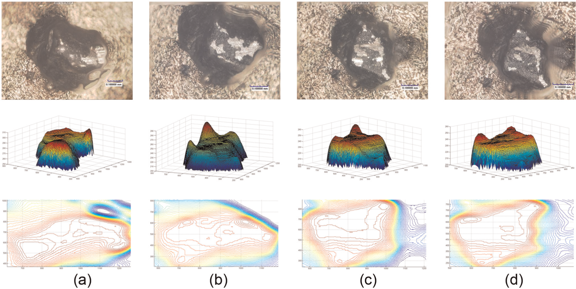
Surface morphology, 3D profiles and counter maps of typical worn PcBN grain cutting edges: (a) V’ = 100 mm3/mm, (b) V’ = 400 mm3/mm, (c) V’ = 600 mm3/mm and (d) V’ = 1100 mm3/mm.
Micro fracture causes of the PcBN grain cutting edges in high-speed grinding
The magnitude and distribution of the grinding load on the single PcBN grain are the causes for the grain micro fracture in high-speed grinding. In order to determine the grinding load on the single grain during grinding, finite element method (FEM) is used based on ABAQUS software, as shown in Figure 7(a) and (b). The arbitrary Lagrangian–Eulerian (ALE) adaptive meshing is used to maintain a high-quality mesh and to prevent the analysis from the errors caused by severe mesh distortion. The workpiece is discretized by 30,000 bilinear four-noded quadrilateral elements with reduced integration (CPE4R). The cBN grain is modeled as an isothermal rigid body with the rake angle of −20°. In the simulation, the bottom edge of the workpiece is constrained in both x- and y-directions, and its left edge is fixed in the horizontal direction.
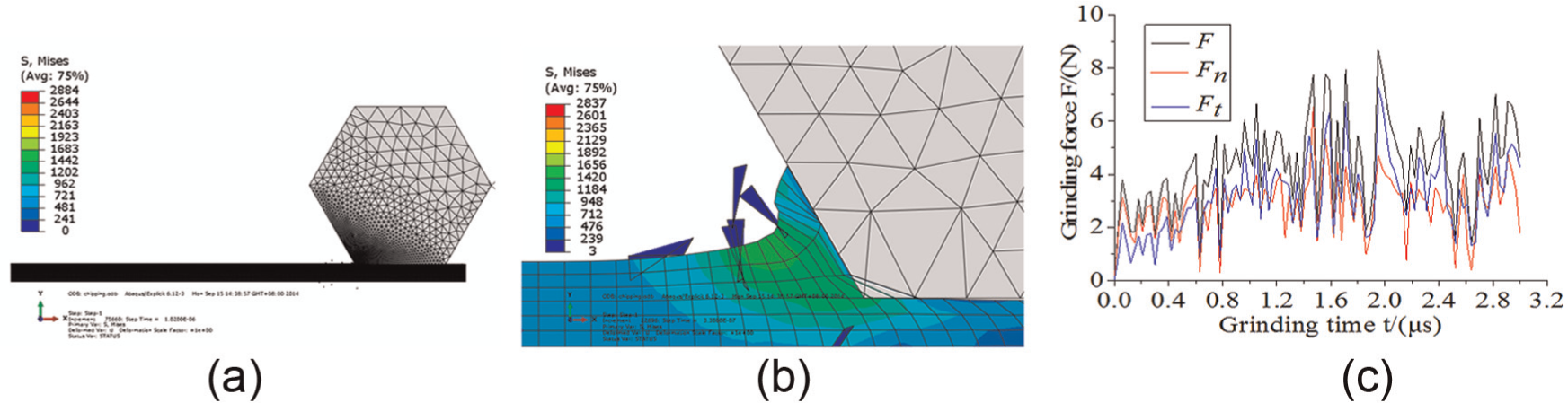
FEM analysis of grinding forces on single grain: (a) simulation model, (b) simulation result and (b) grinding forces.
Figure 7(c) displays the calculated grinding forces, which indicates that once the grain cutting edges contact the workpiece material, the normal force will increase rapidly to about 3 N and the tangential force will increase to 2 N. Subsequently, the grinding forces in Figure 7(c) are loaded on the grain dynamically to analyze the stress within the PcBN grain, as shown in Figure 8(a). The stresses’ result obtained at the working time of 0.02 μs is displayed in Figure 8(b) and (c). It is found that the stress in the cutting edges (red region in the lower left corner of Figure 8(b)) is much larger than that in the other region of the PcBN grain. The reason is that the grain cutting edges in the lower left corner is the zone that first contacts the workpiece material and therefore suffers a large impact load. Moreover, the grinding load could not work in the other region of the grain except the particular cutting edges zone in the quite short time at the initial stage. Under such condition, when the maximum stress is larger than the fracture strength of PcBN grain, micro fracture perhaps occur on the grain top surface due to isotropy.
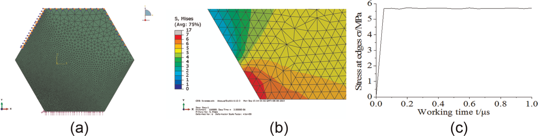
FEM analysis of the grinding load of single grain in high-speed grinding: (a) load model, (b) stress distribution and (c) stress change at cutting edge.
Fractal analysis of typical McBN and PcBN grain cutting edges
According to Figures 5 and 6, the shape of the McBN and PcBN grain cutting edges was variously changed due to the fracture wear and the attritious wear when the accumulated volume of the removal material was increased. Previous research has discovered that the grain surface similar to that shown in Figures 5 and 6 has the fractal nature in a range of mesh size from 2 to 10 μm.26,27 The complexity of the grain wear process, therefore, could be evaluated quantitatively based on 3D fractal dimension. In particular, high fractal dimension of the grain cutting edges could be obtained when the contour lines consist of more complicated short lines, as shown in Figures 5 and 6. Figure 9 displays the calculation process of the fractal dimension of the grain cutting edges based on the counter lines. The relationships between mesh size δ and surface area S(δ) are accordingly obtained. Complex change of the relationship is observed for the grain cutting edges with the increasing accumulated volume of the removal material.
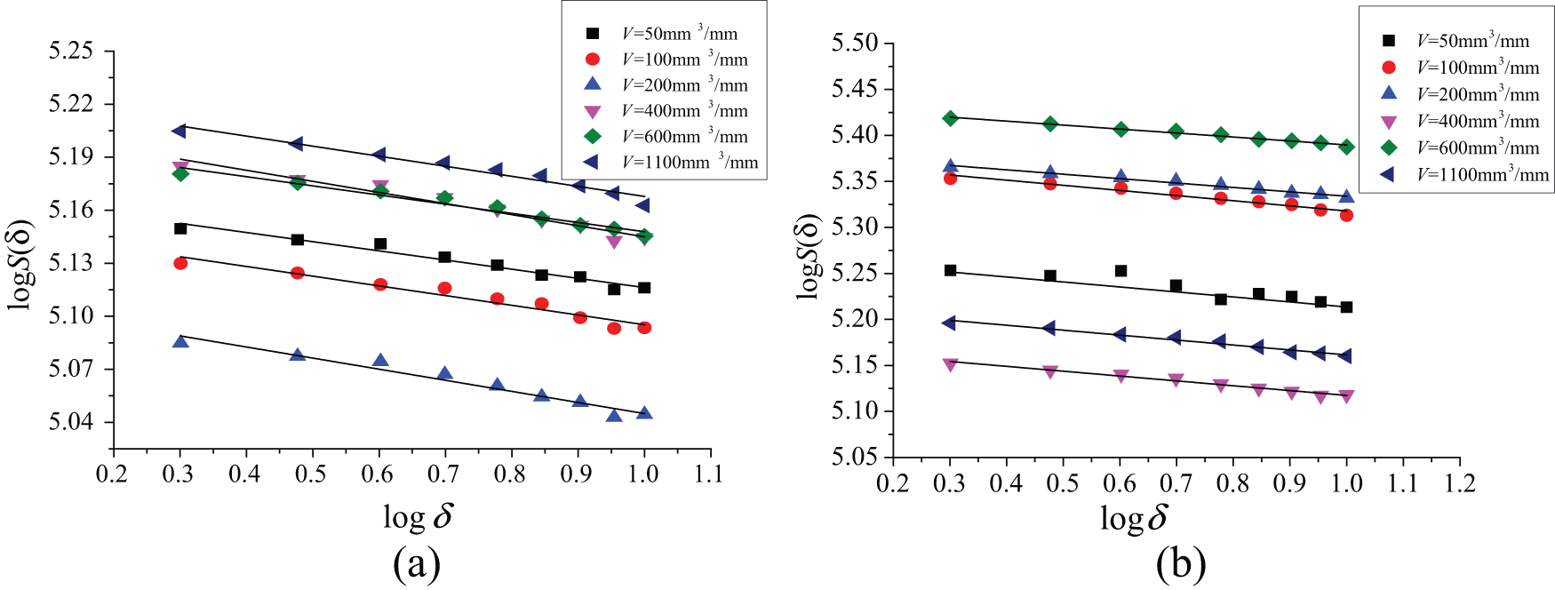
Figure 10 shows the changes in the fractal dimension of the grain cutting edges versus the accumulated volume of the removal material in the high-speed grinding process. As seen in Figure 10(a), the McBN grain first took the low values of fractal dimension, that is, 2.032–2.035, due to an increase in the attritious wear area when the stock removal was from 50 to 100 mm3/mm. Afterwards, because the attritious wear area decreased and new sharp cutting edges were formed due to the large fracture and micro fracture, the fractal dimension of McBN cutting edges tended to increase to the maximum value, Ds = 2.044, between the stock removals from 100 to 200 mm3/mm. However, the fractal dimension value went down due to the significant large fracture behavior over a range of stock removals from 200 to 400 mm3/mm. Furthermore, between the stock removals from 400 to 600 mm3/mm, an increase in the fractal dimension was found due to the increase in micro fracture. Finally, the fractal dimension of the McBN grain cutting edges decreased gradually due to large fracture over a range of stock removals from 600 to 1100 mm3/mm.
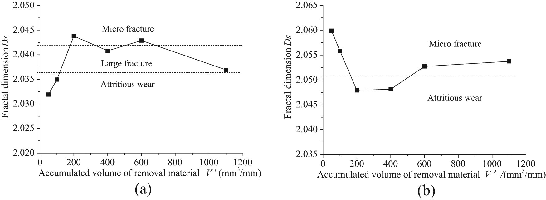
Changes in the fractal dimension of the grain cutting edges: (a) McBN grain and (b) PcBN grain.
According to Figure 10(b), compared to the fractal dimension of the McBN grain cutting edges, the different changes in the fractal dimension of the PcBN grain cutting edges occurred during high-speed grinding, though the identical grinding parameters were applied. The maximum value of the fractal dimension, that is, Ds = 2.060, was obtained when the stock removal was 50 mm3/mm. Afterwards, the fractal dimension decreased significantly due to an increase in the attritious wear and a decrease in micro fracture between the stock removals from 50 to 200 mm3/mm. Moreover, between the stock removals from 200 to 400 mm3/mm, a stable value of the fractal dimension, that is, Ds = 2.048, was taken due to the attritious wear. And then, over a range of stock removals from 400 to 600 mm3/mm, the fractal dimension increased because the micro fracture occurred. Finally, the fractal dimension was almost kept constant at 2.053 due to the repeating micro fracture of the PcBN grain when the stock removal material was from 600 to 1100 mm3/mm.
In brief, according to Figure 10, it is known that the wear behavior of the McBN grain cutting edges was, in order, attritious wear → large fracture → micro fracture → large fracture → attritious wear, while that of the PcBN grain cutting edges was micro fracture → attritious wear → micro fracture in the high-speed grinding process.
Fractal analysis of McBN and PcBN wheels in high-speed grinding
The self-sharpening phenomenon of the grinding wheel could be understood based on the fractal dimension of large quantities of grain cutting edges. In the current investigation, 30 McBN grains and 30 PcBN grains were selected randomly from the eight symmetrical regions of the grinding wheel. The fractal dimension of the cutting edges of these grains was calculated at different stock removals. Figure 11 displayed the corresponding results obtained at the stock removal of 50 mm3/mm. Furthermore, the statistical information of the fractal dimension of the McBN and PcBN wheels was accordingly obtained after several grains with particular large or small value of fractal dimension were discarded.
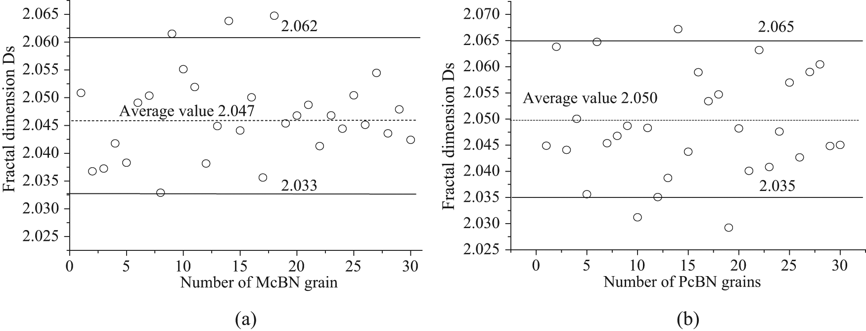
Fractal dimension of different wheels for the accumulated volume of removal material of 50 mm3/mm: (a) McBN wheel and (b) PcBN wheel.
As seen in Figure 11, for the McBN wheel, the fractal dimension of grain cutting edges is from 2.033 to 2.062 with an average value of 2.047. For the PcBN wheel, however, the fractal dimension is ranged from 2.035 to 2.068 with an average value of 2.050.
The average value of the fractal dimension of the grinding wheels versus the accumulated volume of material removed per unit grinding width V′ is illustrated in Figure 12. The average value of the fractal dimension is 2.040–2.047 for the McBN wheel and 2.049–2.054 for the PcBN counterpart in high-speed grinding. Moreover, the former is always lower than the latter. Ichida et al. 26 found that the fractal dimension of the fine cutting edges formed due to micro fracture is always higher than that of the rough cutting edges formed due to large fracture and attritious wear. Therefore, it is known that the PcBN grain cutting edges are finer than those of the McBN counterparts, which could enhance the self-sharpening phenomenon and improve the grinding performance of the PcBN wheel.
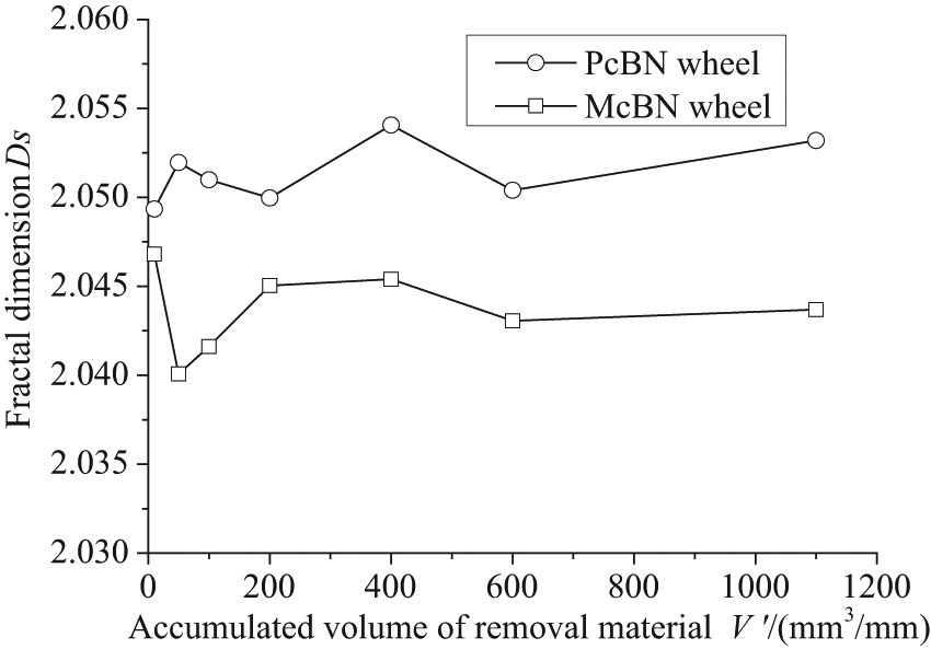
Changes in the average fractal dimension of the McBN and PcBN wheels.
Radial wear of the McBN and PcBN wheels in high-speed grinding
The radial wheel wear is another important parameter to characterize quantitatively the wear-resistance ability of the grinding wheels. In this investigation, the sequential reduction of the protrusion height of 30 grains for each wheel was measured, the average value of which was calculated and analyzed to reflect the radial wear of the monolayer brazed wheels. The results are provided in Figure 13 as plots of radial wheel wear versus accumulated volume of removal material per unit width of grinding.
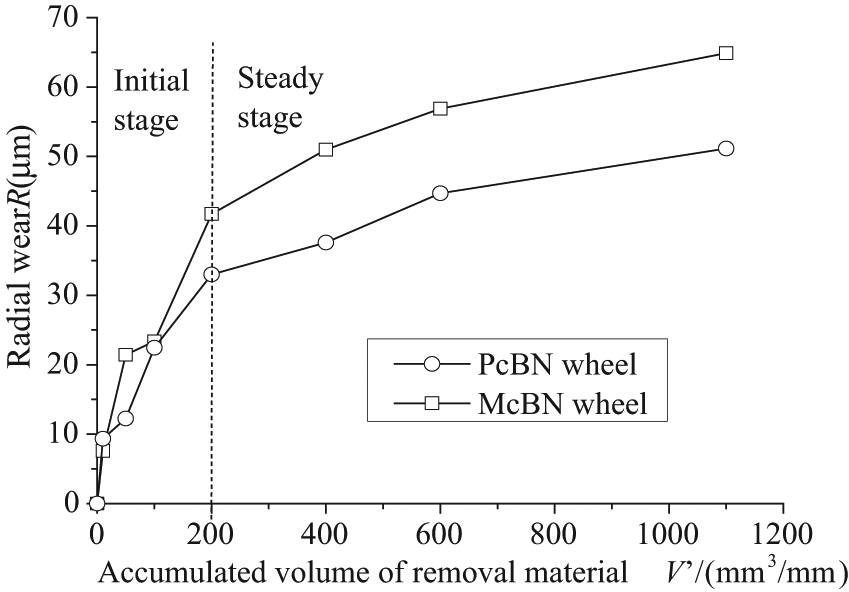
Radial wear of the McBN and PcBN wheels.
In general, there is an initial transient run-in wear stage with the radial wheel wear of 30–40 μm at a decreasing rate to a steady-state wear stage at a lower wear rate for each wheel. The slope in the steady-state wear region tends to be smaller. On the other hand, the wear-resistance ability of the PcBN wheel is always better than that of the McBN wheel in the grinding process. The radial wheel wear at the termination of testing is arrived at approximately 65 μm for McBN wheel and 50 μm for PcBN wheel. How to further reduce the radial wear of the PcBN wheel by decreasing the grain micro fracture will be an important issue for improving the grinding performance of PcBN wheels in the subsequent investigation.
Influence of self-sharpening phenomenon on grinding force, forces ratio and ground surface
Grinding force and forces ratio could reflect the effects of the self-sharpening phenomenon of the grinding wheels. Good self-sharpening phenomenon corresponds to high wheel sharpness, which could produce low grinding force and forces ratio. Figure 14 displays the grinding force and forces ratio versus the accumulated volume of removal material per unit width during grinding nickel superalloy Inconel718.
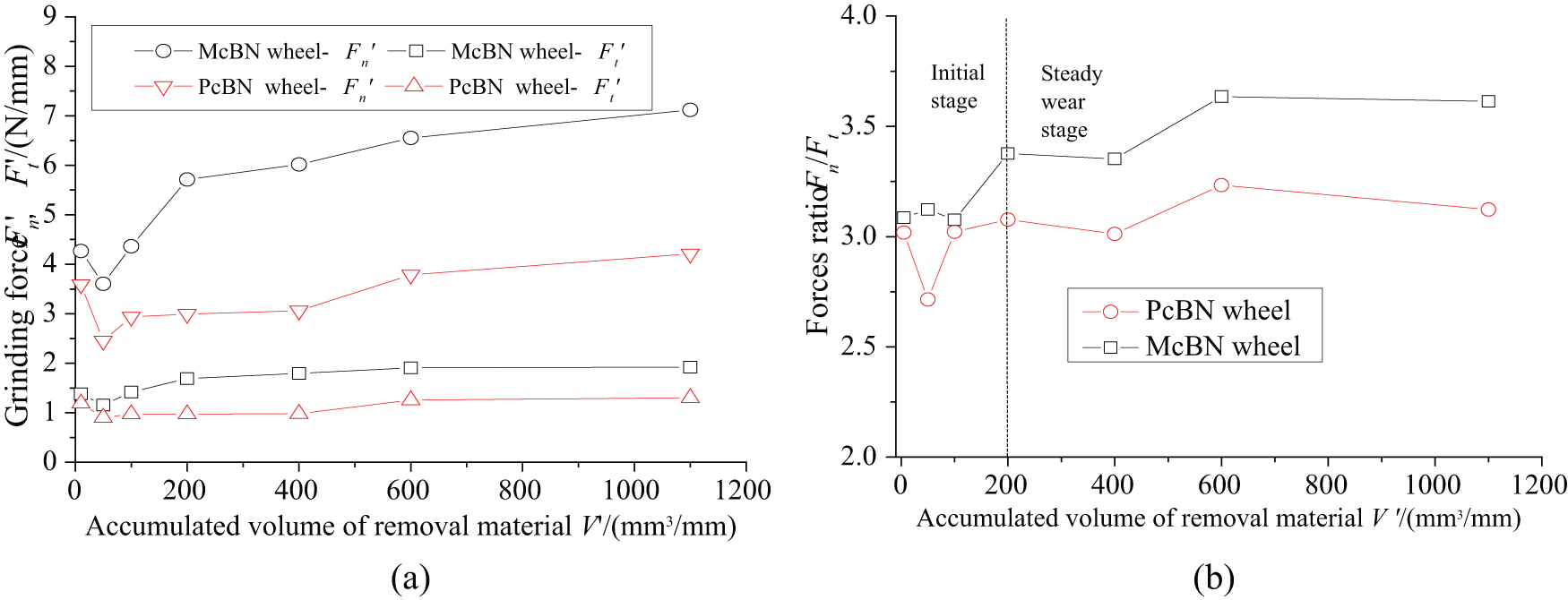
Grinding force and forces ratio versus accumulated volume of removal material: (a) grinding force and (b) forces ratio.
As seen in Figure 14(a), for the McBN wheel, the normal force
The grinding forces ratio of normal force Fn to tangential force Ft is correlated to the change in the sharpness degree of the grinding wheel. Small value of the forces ratio always corresponds to good ability to keep high sharpness. Figure 14(b) shows the forces ratio versus the stock removal material. The forces ratio of both the McBN and PcBN wheels did not keep constant in the initial grinding stage until the stock removal reached 200 mm3/mm. In the steady grinding stage, the forces ratio was increased from 3.1 to 3.6 for the McBN wheel, while it was increased from 2.8 to 3.2 for the PcBN wheel. Obviously, the PcBN grinding wheel had the better capacity than the McBN wheel to keep high sharpness. The excellent wear-resistance ability and self-sharpening phenomenon were obtained due to the main micro fracture behavior of PcBN grains during grinding. However, for the McBN grains, the attritious wear and the large fracture were the primary wear patterns, and the micro fracture behavior and self-sharpening capacity were generally bad.
Additionally, the ground surface obtained in the steady wear stage of the grinding wheels is also compared. The surface roughness Ra of the ground surface is 0.35 μm with McBN grains and 0.28 μm with PcBN grains. Figure 15 shows the morphology of the ground surface, from which it is found that the flaws in the surface ground with PcBN grains are much smaller than those with McBN grains. Accordingly, lower surface roughness and smaller surface defects are obtained due to the high sharpness degree of the PcBN grains.
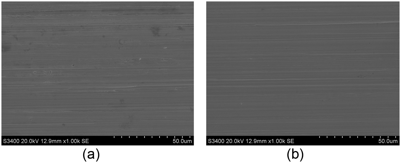
Ground surface with different grains: (a) surface ground with McBN grains and (b) surface ground with PcBN grains.
Conclusion
Comparative investigation on the wear behavior and self-sharpening phenomenon of PcBN grains and McBN grains in high-speed grinding was carried out. The presented results and related discussion lead to the following conclusions:
Different wear process is obtained for the PcBN grains and McBN grains with the increasing accumulated volume of removal materials. The wear behavior of the McBN grain cutting edges is, in order, attritious wear → large fracture → micro fracture → large fracture → attritious wear, while that of the PcBN grain cutting edges is micro fracture → attritious wear → micro fracture.
Micro fracture of the PcBN grain takes place easily in the particular zone where large impact load is formed due to the first contact between the grain cutting edges and the workpiece material.
The average value of the fractal dimension of the McBN wheel, 2.040–2.047, is always lower than that of the PcBN wheel, 2.049–2.054, which indicates that the PcBN grain cutting edges are finer than those of the McBN counterparts.
Compared to the McBN wheel, the advantages of the PcBN counterpart include smaller radial wheel wear, lower grinding force and forces ratio and better ground surface, which is contributed to the self-sharpening phenomenon due to grain micro fracture during high-speed grinding.
Footnotes
Appendix 1
Appendix 2
Declaration of conflicting interests
The authors declare that there is no conflict of interest.
Funding
The authors gratefully acknowledge the financial support of this research by National Natural Science Foundation of China (No. 51235004, No. 51375235), Fundamental Research Funds for the Central Universities (No. NE2014103), Qinglan Project and 333 Project of Jiangsu Province.