
Abstract
Time-optimal feedrate planning theory has been widely applied in high-speed machining to improve machining efficiencies with a specified trajectory accuracy by fully exploiting the capabilities of high-speed computer numerical control machine tools. Reasonable and effective constraints conforming to practical situations are necessary conditions for obtaining optimal planning results. In this article, complex constraints, such as the motor torque constraint, the contour error constraint, the friction error constraint, the instruction velocity constraint and the smooth velocity constraint, are investigated in depth. Moreover, an efficient convex optimisation method is developed to address the time-optimal feedrate planning problem with these complex constraints. The experimental results from two feedrate planning tests and the computational efficiency for a test trajectory demonstrate the validity, stability and high efficiency of the proposed approach.
Introduction
Increasing requirements on the complexity, precision and productivity of modern products have brought about increasingly greater challenges in terms of the performance of high-speed computer numerical control (CNC) machine tools, which is mainly determined by the tool’s kinematics, structural dynamics, high-speed CNC system and machining processes. 1 Significant improvements in accuracy and efficiency can be realised for a complex trajectory by fully exploiting system capabilities in the feedrate planning stage. The feedrate planning problem has usually been associated with the time-optimal (or minimum-time) framework, which was originally adopted to search for the solution of the time-optimal control problem for robotic actuators. The result is that the shortest machining time under a specified machining accuracy can be acquired without exceeding the system capabilities of high-speed CNC machine tools.
Since the 1980s, time-optimal feedrate planning has been widely applied in the robotics and CNC manufacturing fields. Based on bang–bang control theory, the Phase Plane Method (PPM)2–4 was first developed to realise the minimum traversal time for robotic actuators. Throughout the motion, at least one of the actuators must be running under the maximum acceleration or deceleration condition. The planning results are obtained using the velocity-limited curve (VLC) and the switch points that are found by forward recursive and reverse iterations. Timar and colleagues5,6 extended the PPM to CNC feedrate planning. The problem of computing the feedrate variations for minimising the movement time along a path described by a polynomial parametric function was solved by considering both fixed and speed-dependent axis acceleration bounds derived from the drive motor current and voltage ratings. However, the PPM is generally suitable for a simple model containing velocity and acceleration constraints and is known to poorly address various other complex constraints. Meanwhile, the computations of the PPM can easily become extent and even exhibit exponential increases in complexity, especially for high-order models.
Along with the enhancement of the computational performance, the numerical method, as opposed to the analytical method, has gradually been adopted in time-optimal feedrate planning studies. The direct method has become a research focus because it can effectively convert the time-optimal feedrate planning problem into a static optimisation problem by scattering the continuous-time model. A corresponding solution method is also needed because of the different structures and characteristics of the problem model. Renton and Elbestawi 7 developed an efficient two-pass algorithm for time-optimal feedrate planning. Their algorithm uses the full performance envelope of each axis for a given trajectory and reduces the path error. Bieterman and Sandstrom 8 proposed a similar variable feedrate optimisation procedure that incorporates the velocity and acceleration constraints for pocket machining. Sencer et al. 9 considered the velocity, acceleration and jerk to search for the optimal solution using a commercial planning function library. Zhang et al. 10 proposed an efficient linear programming method to address the time-optimal feedrate planning problem for a parametric tool path under the specified feedrate bound, acceleration bound and chord error bound. This approach successfully avoids computing the expressions of the VLC and switching points and can produce a near-time-optimal solution with continuous accelerations. Recently, Zhang and Li 11 introduced the sequential quadratic programming (SQP) method for the feedrate planning model based on the jerk constraint, where the strong nonlinearity due to the jerk is eliminated using a pseudo velocity constant instead of the velocity variable. The SQP method can achieve the globally optimal solution but suffers from low computational efficiency.
To more efficiently obtain the time-optimal solution, Verscheure et al. 12 employed the convex optimisation method for the motion control of a robot. The time-optimal feedrate planning problem is transformed into a convex optimal control problem with a single state through a nonlinear change of variables. The convex optimisation method has a special property whereby any local optimum is also globally optimal and is quite suitable for large-scale engineering problems with real-time requirements because its computational efficiency is approximately equal to that of the linear programming method. It is clear that the higher solution efficiency and path accuracy could be realised if the CNC time-optimal feedrate planning problem was addressed by the convex optimisation method. However, many difficulties exist because the objective function and constraints of the CNC feedrate planning model are very different from those of the robot motion control problem. Guo et al. 13 utilised a finite-state convex optimisation method to efficiently perform the time-optimal feedrate planning of a high-order CNC servo system. However, the model only considers the constraints, such as the velocity, acceleration, jerk and tracking error, and is still solved using the SQP method.
According to the above analyses, time-optimal feedrate planning is essentially a mathematical programming problem, where reasonable and effective constraints conforming to the actual situation are the conditions required to obtain optimal planning results. In most studies, the velocity constraint, the acceleration constraint and the jerk constraint are generally under consideration.14–17 The acceleration constraint and the jerk constraint are expected to reduce inertia, prevent shock and smooth velocity. However, for high-speed machining (HSM), these constraints have been shown to be unable to fully exploit the potential of high-speed CNC machine tools for a given machining accuracy due to the high machining speed and the possible frequent reversing requirement. First, each axis of high-speed CNC machine tools is generally actuated by a direct current servo motor with a ball screw transmission. The actual motor torque constraint rather than the simplified acceleration constraint should be employed for time-optimal feedrate planning. Second, the contour error should be considered as an important constraint for time-optimal feedrate planning. The CNC servo feed system follows the location input instruction of each axis. Various feedforward and feedback control strategies are executed to obtain a smaller following error. However, the tracking accuracy of each axis is not consistent for multi-axial linkage machining, which leads to the result that the overall contour accuracy is determined by the individual axis with the largest instantaneous following error. Moreover, the contour error can directly reflect the contour accuracy because the contour error indicating the minimum distance between the current actual location and the desired trajectory is coupled by the following error of each axis. Much research has also shown that even though the following error of each axis is not improved, properly compensating for the contour error can significantly increase the final contour accuracy.18,19 In addition, the friction error is also the important part of the dynamic error of each axis and has a significant impact on the precise position control of a high-speed CNC system, particularly for complex machining trajectories. 20 However, the friction error, occurring at the quadrant boundary when an axis changes its direction, is difficult to address because of the complexity and uncertainty of the existing theoretical model of friction. In previous studies, the friction error was often simplified as a constant. However, many experiments have shown that the friction error varies as a function of the feed velocity and the trajectory curvature.
Therefore, in addition to the conventional velocity constraint and the smooth velocity constraint, complex constraints in HSM, such as the motor torque constraint, the contour error constraint and the friction error constraint, are extensively investigated in this article. Then, an efficient convex optimisation method for time-optimal feedrate planning with these complex constraints is developed and demonstrated through experiments and numerical analyses for a test trajectory. This article is organised as follows. Section ‘Complex constraints’ discusses the motor torque constraint, the contour error constraint, the friction error constraint, the instruction velocity constraint and the smooth velocity constraint in detail. Section ‘Convex optimisation method for time-optimal feedrate planning’ describes the problem of time-optimal feedrate planning with these complex constraints and presents an efficient convex optimisation method to solve this problem. In section ‘Experimental verification’, the numerical experiments are implemented to verify the effectiveness of the proposed approach. Finally, section ‘Conclusion’ gives the concluding remarks.
Complex constraints
Motor torque constraint
In the armature control mode of the direct current servo motor employed in high-speed CNC machine tools, the voltage signal is used as the control command on the field winding with the following relations
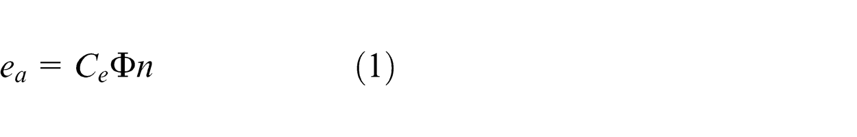
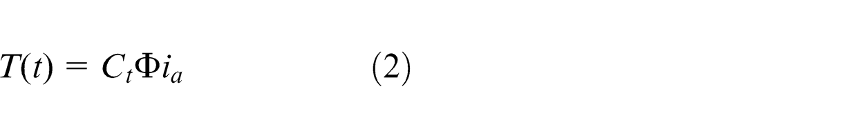
The above equations incorporate the induced electromotive force
In practice, the heating problem defines the current limitation and subsequently determines the motor torque constraint, that is, the maximum armature voltage
where
According to the above discussions, the velocity
where
Given an arbitrary curve of a machining trajectory expressed as
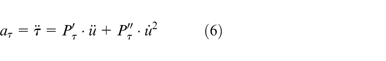
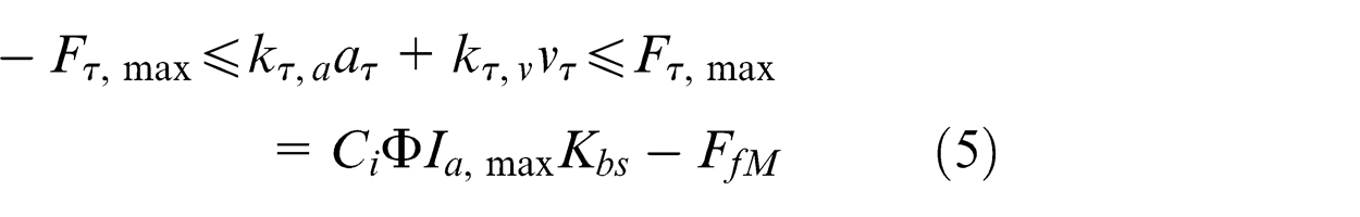
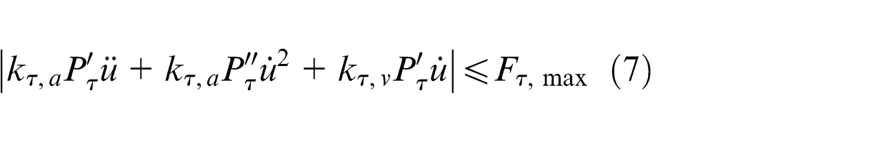
Based on equations (5) and (6), the motor torque constraint can be written as
Contour error constraint
The simplified dynamic model of the servo feed system is shown in Figure 1. It can be observed that each axis velocity increases with increasing gains
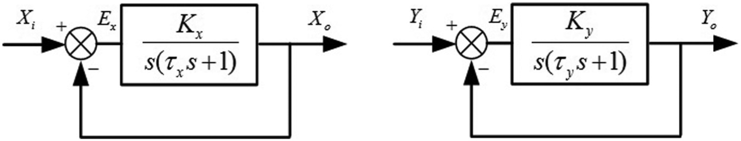
Dynamic model of the servo feed system.
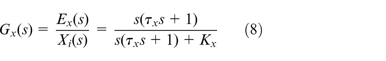
Taking the X-axis as an example, the transfer function of the transient error
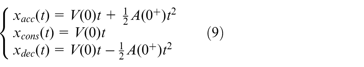
For the trapezoidal acceleration and deceleration mode, each axis input includes three cases: speed up with a constant acceleration, constant speed and speed down with a constant acceleration. Supposing that
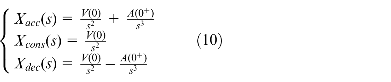
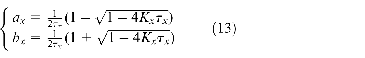
Based on the Laplace transformation, equation (9) can be written as
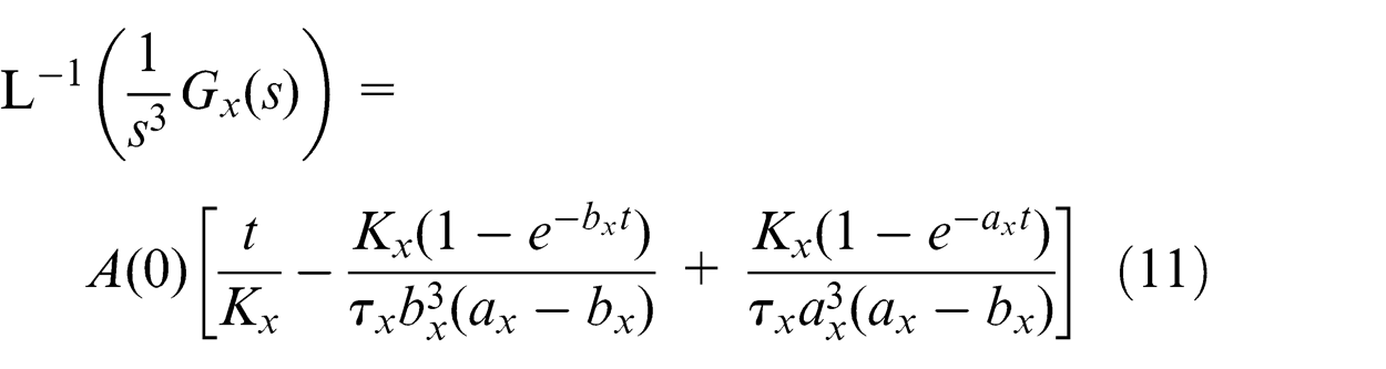
Therefore, when the system input is a linear combination of
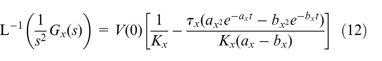
where
Based on the constant velocity phase
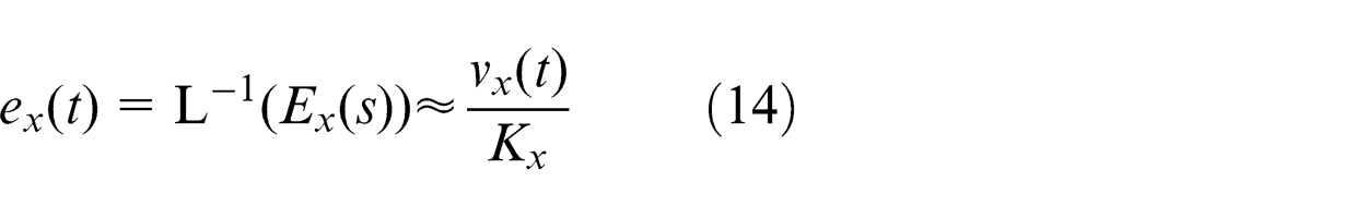
Similarly, the following error for the Y-axis is defined by
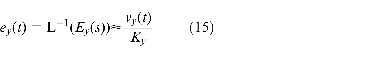
Therefore, the following error of an individual axis can be written in the form
where
Now, the relation between the contour error and the feed velocity can be established through the following errors of the individual axes discussed above. In Figure 2,
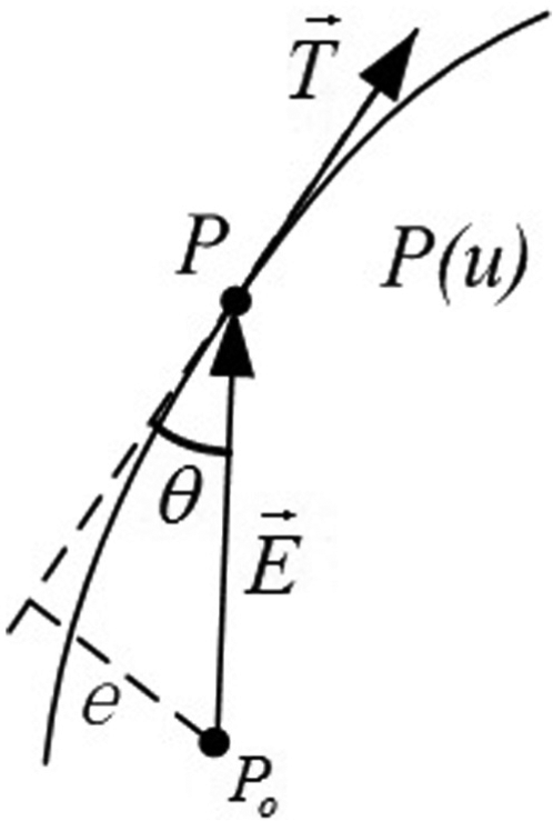
Schematic diagram of the contour error.
The angle
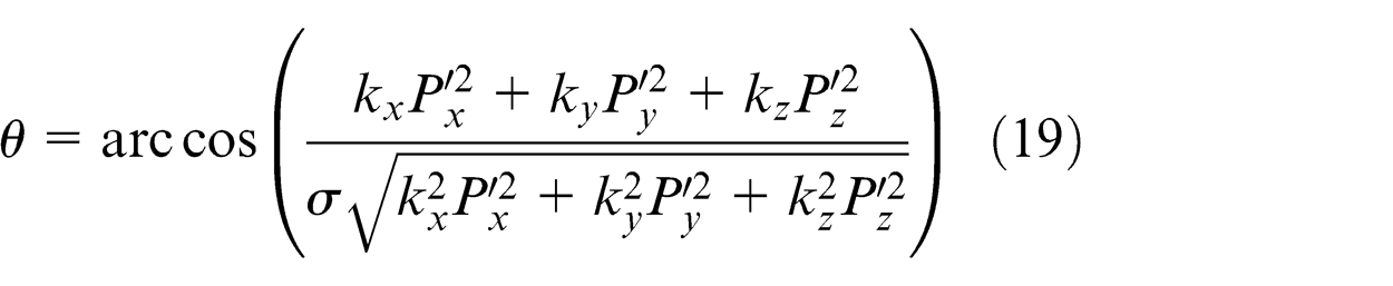
Finally, we can obtain the contour error constraint as follows
Friction error constraint
To obtain the friction error constraint, the feed servo system, including the friction, must first be modelled and analysed. The block diagram of the feed servo system is shown in Figure 3.
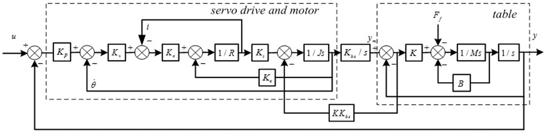
Block diagram of the feed servo system.
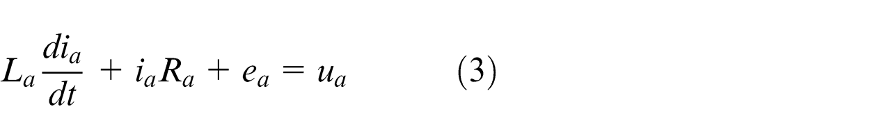
The feed servo system is typically composed of the servo drive, the servo motor and the table, wherein the servo drive includes the position loop, the velocity loop and the current loop. Without regard to the mechanical damping and the inductance of the motor, the current differential equation can be expressed as
where
The translational motion of the table is generated from the rotation of the motor by a ball screw. Suppose that the connection between the ball screw and the table is elastic. The relevant torque equilibrium equation is obtained as follows
where
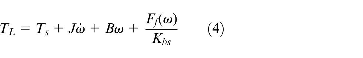
The torque equilibrium equation of the table is then given as follows
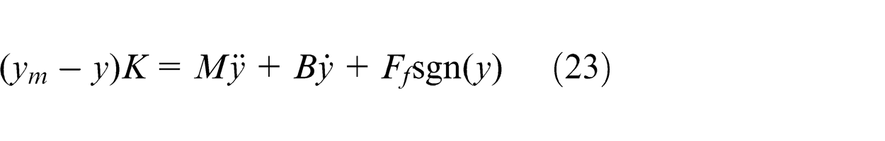
where
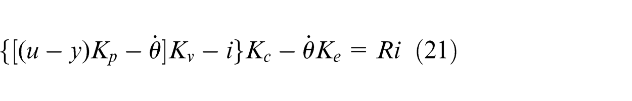
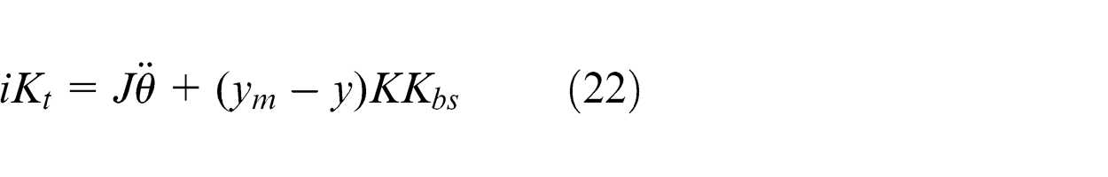
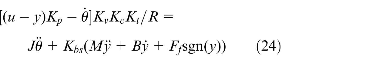
Based on the axial dynamic performance, the relation between the current and the motor torque can be assumed to be linear. Based on equations (21)–(23), the differential equation of the feed servo system can be expressed as
Until now, the relation between the feed servo system and the friction could be constructed using the orthogonal experiment method described by Mei et al. 20 We can obtain the friction error constraint as follows

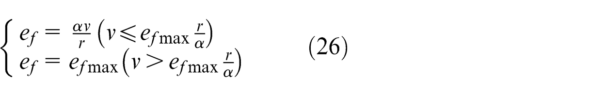
where
Suppose that
The friction error constraint can thus be written as
Other constraints
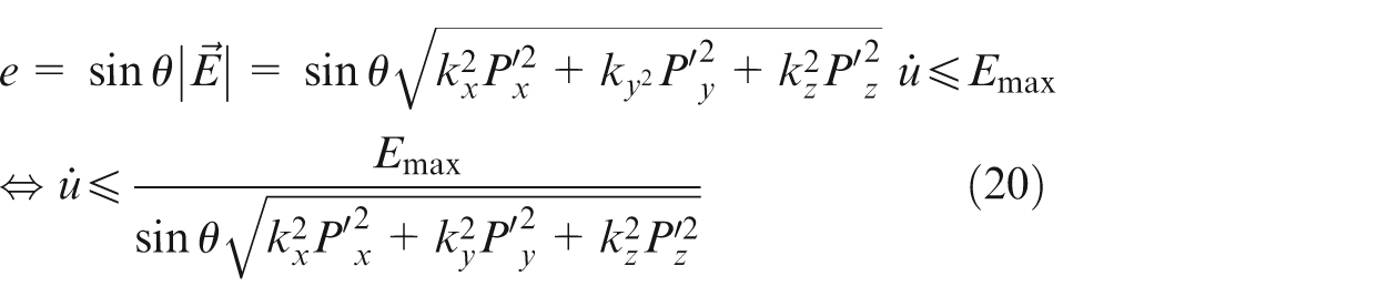
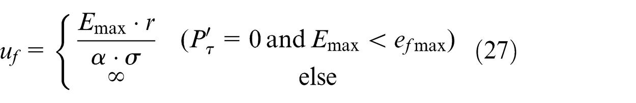
Except for the three main constraints discussed above, the instruction velocity constraint and the smooth velocity constraint should also be introduced into the time-optimal feedrate planning process. The instruction velocity should satisfy the inequality
where
The regularisation function is adopted to obtain the smooth velocity, which provides the benefits of convenience and flexibility. The quadratic smooth function is defined by
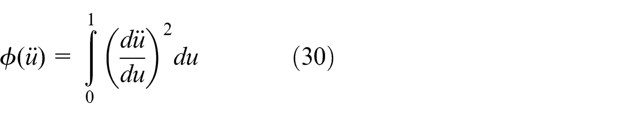
Subsequently, we can achieve a smooth velocity by adjusting the smooth factor
Convex optimisation method for time-optimal feedrate planning
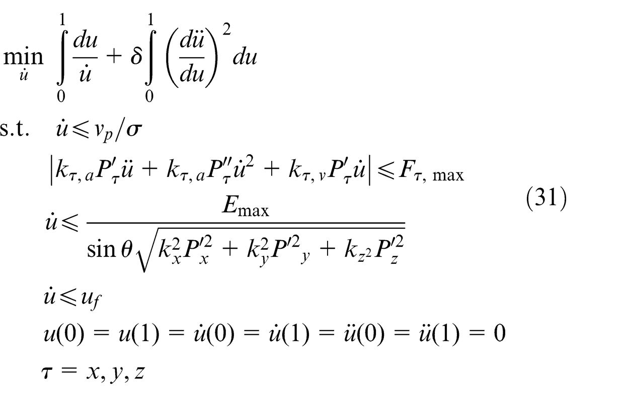
Description of the time-optimal feedrate planning problem
For an arbitrary curve of a machining trajectory defined by
Because
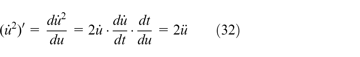
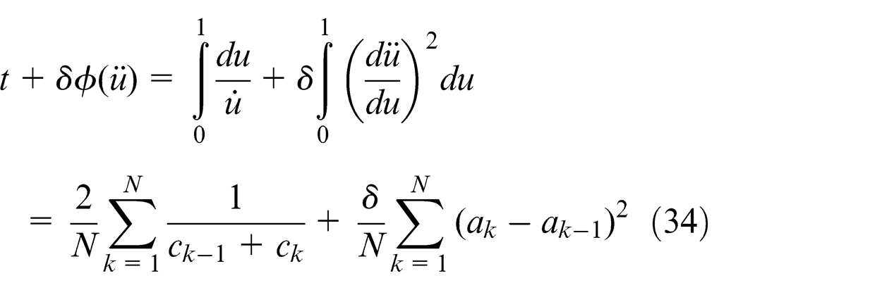
Using equation (32), the equation below can be obtained
Suppose that the parameter velocity in each segment equals the average of the corresponding terminal velocity. Then, the objective function can be written as
Similarly, the instruction velocity constraint, the contour error constraint and the friction error constraint can be written as
Furthermore, suppose that
In addition, the motor torque constraint can be written as
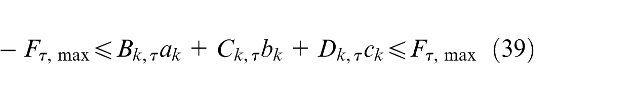
where
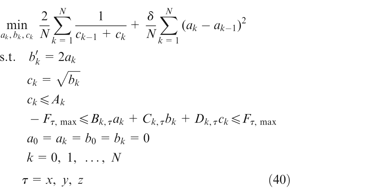
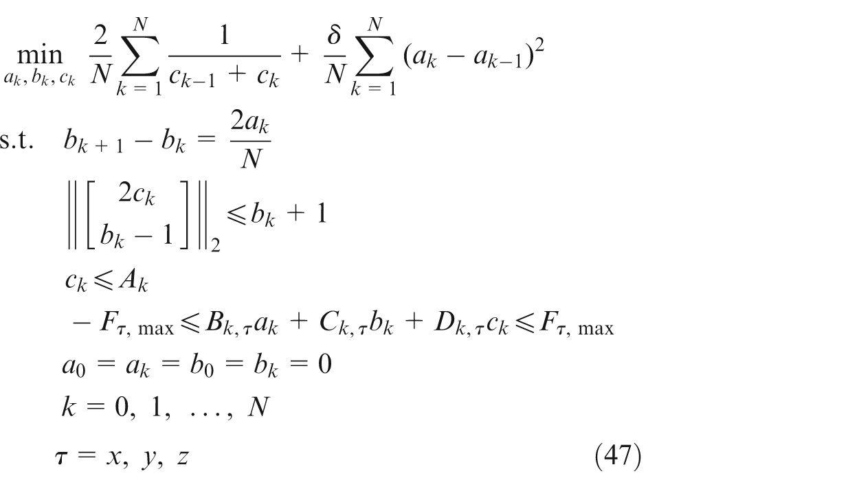
Finally, the time-optimal feedrate planning problem in equation (31) can be converted into the following static optimisation problem
Convex optimisation model with complex constraints
To use the convex optimisation approach for solving the time-optimal feedrate planning problem, the mathematical model of the optimal problem in equation (40) should satisfy three requirements: the objective function must be convex, the inequality constraint must be convex and the equality constraint must be affine. However, here, the objective function and constraints are all non-convex. In this section, we focus on the conversion of the convex optimisation problem.
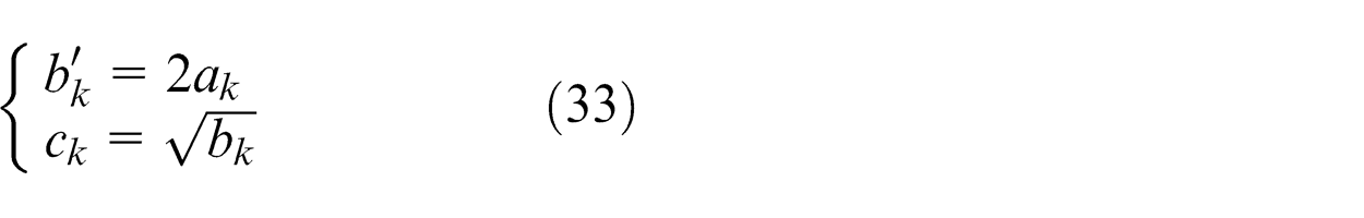
First, the objective function is investigated. Suppose that we have functions
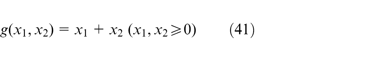
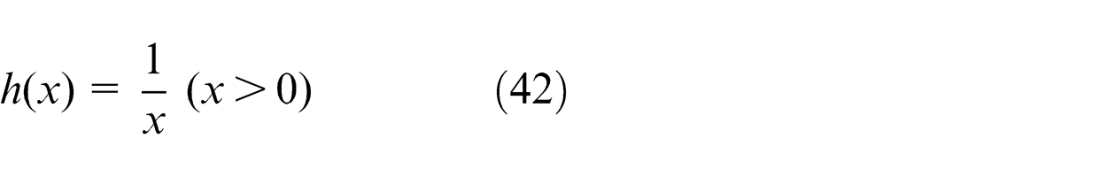
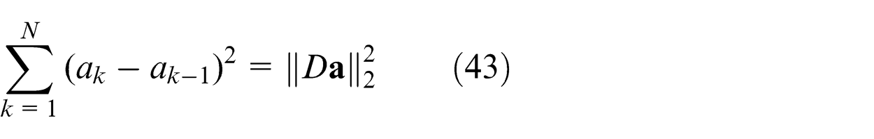
where
Note that the function
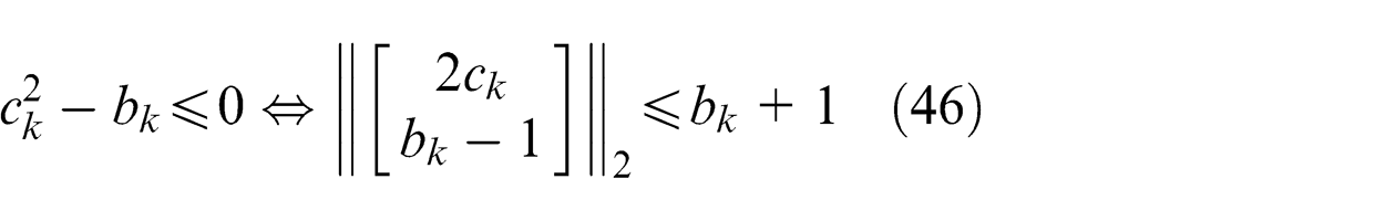
Second, because
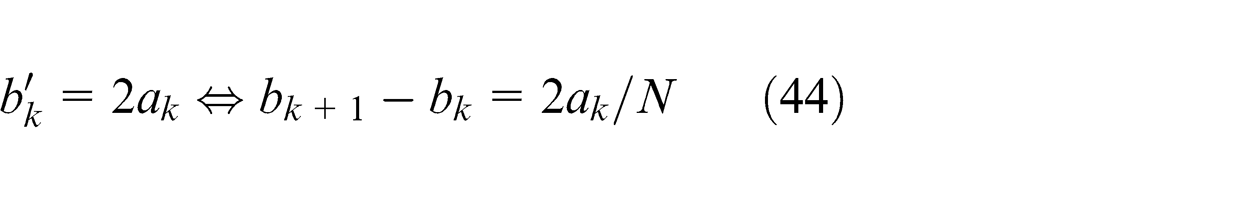
the constraints

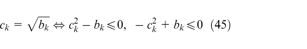
where the inequality
Finally, we can obtain the following mathematical model of the convex optimisation method for the time-optimal feedrate planning problem
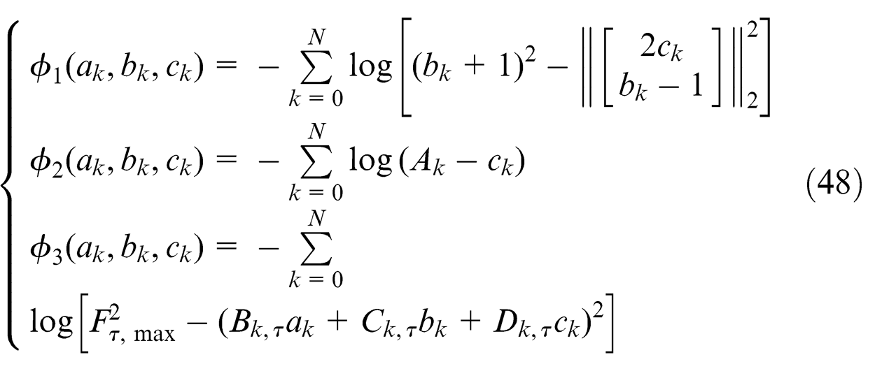
In this article, the interior point method is used to search for the optimal solution of the above convex optimisation model. Obviously, the inequality constraint problem must be converted into the equation constraint problem by moving the three inequality constraints into the objective function. To this end, the following logarithmic barrier functions are introduced
Ultimately, the convex optimisation problem is translated into the equation constraint problem as follows
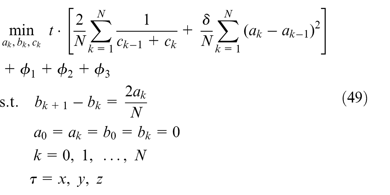
where
The complete solution process for equation (49) is as follows
Initialise
If
Increase
Return to (1).
In the above process, the parameter
Experimental verification
To obtain intuitive experimental results without affecting the validation process of the proposed convex optimisation method for the time-optimal feedrate planning with complex constraints, the test trajectory shown in Figure 4 is designed to perform a motion along two axes with a sharp reversal of the Y-axis. The numerical experiment is implemented on a 32-bit operating system with a 3.2 GHz central processing unit (CPU) using the MATLAB programming language.
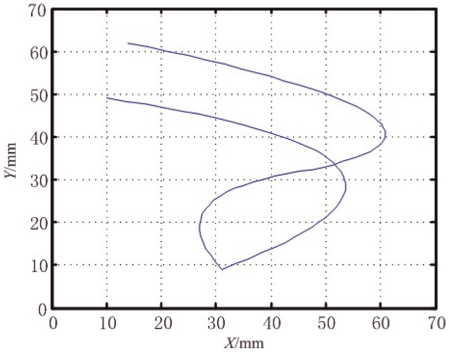
The test trajectory.
The parameters in this experiment are set as follows: the instruction velocity
In Figure 5(a), the VLCs for the contour error constraint and the instruction velocity constraint are shown and are indicated by the dashed line and the solid line, respectively. Figure 5(b) shows the final VLC. Note that the contour error is the main influencing factor for the velocity limitation.
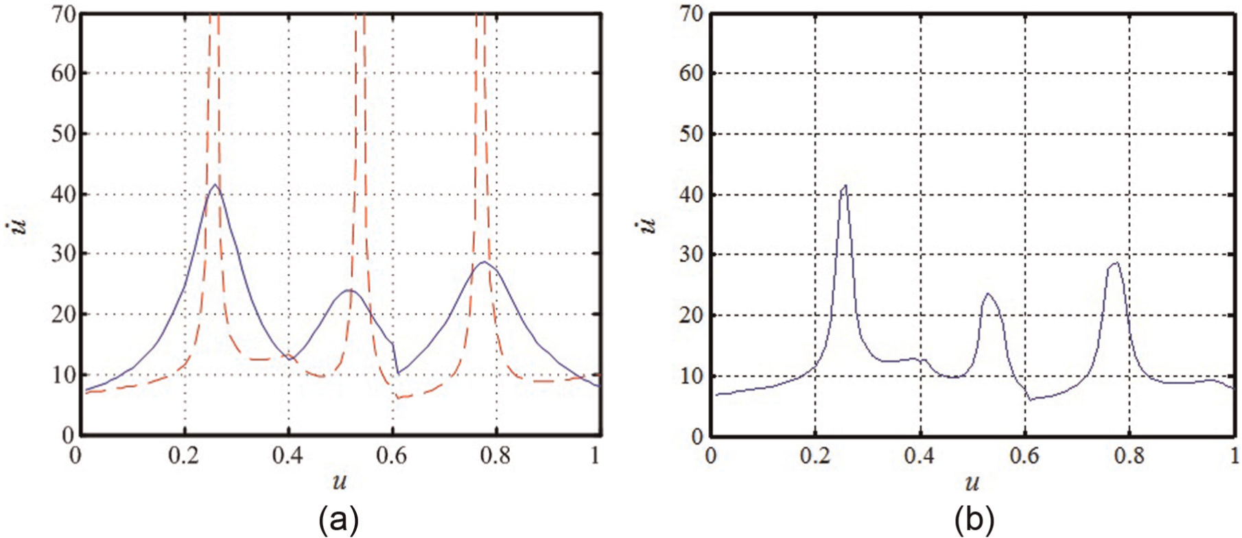
VLC for the contour error constraint and the instruction velocity constraint: (a) the contour error and the instruction velocity constraints and (b) the final VLC.
The first test for the smooth factor
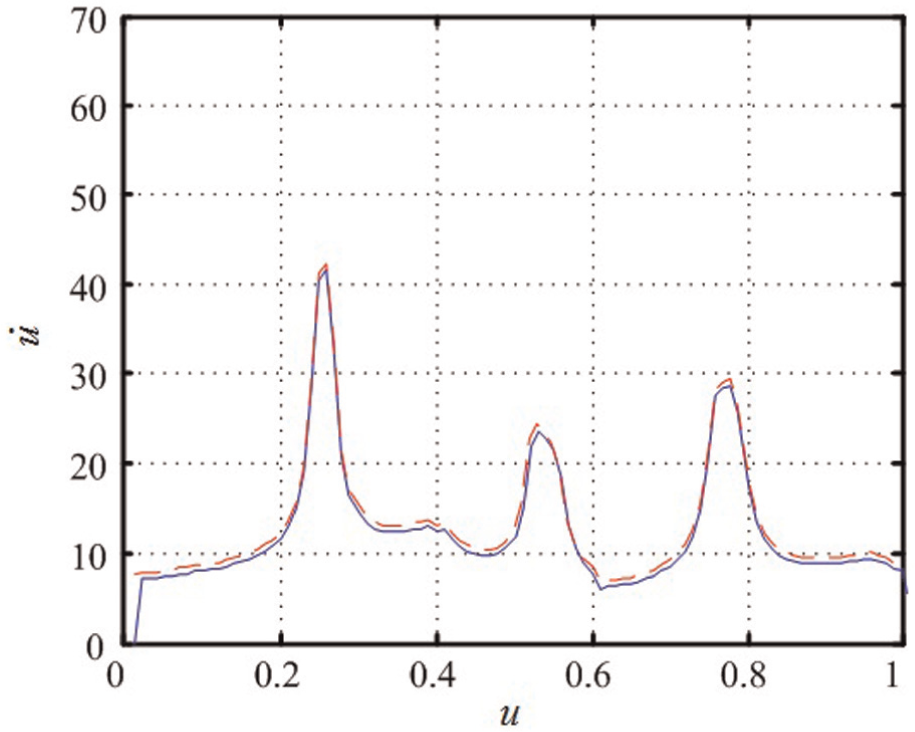
Results of the feedrate planning for the first test.
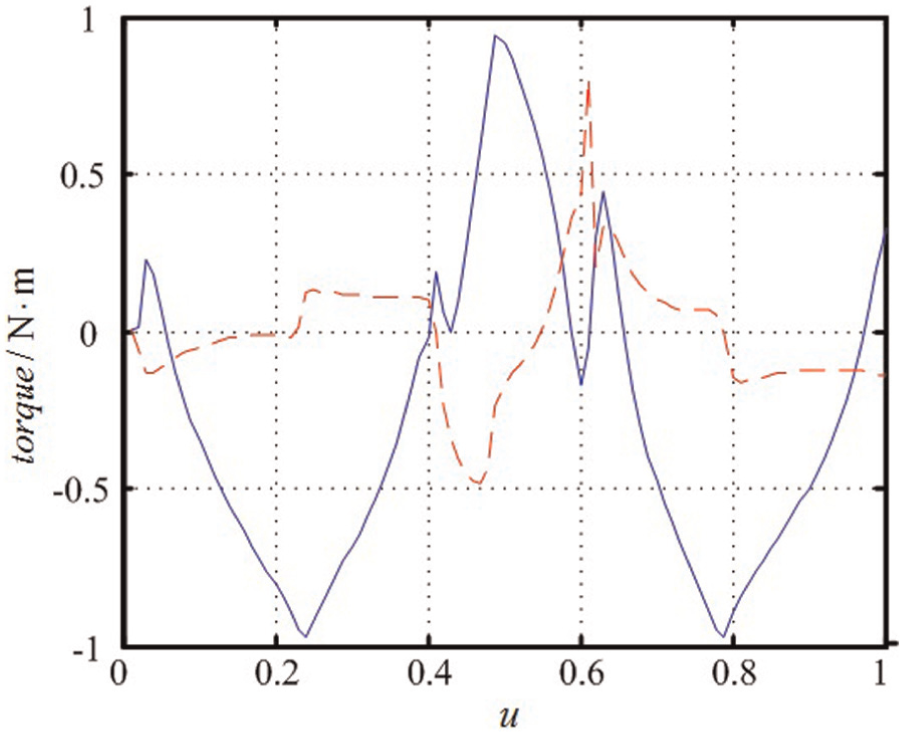
Curves of the motor torque for the first test.
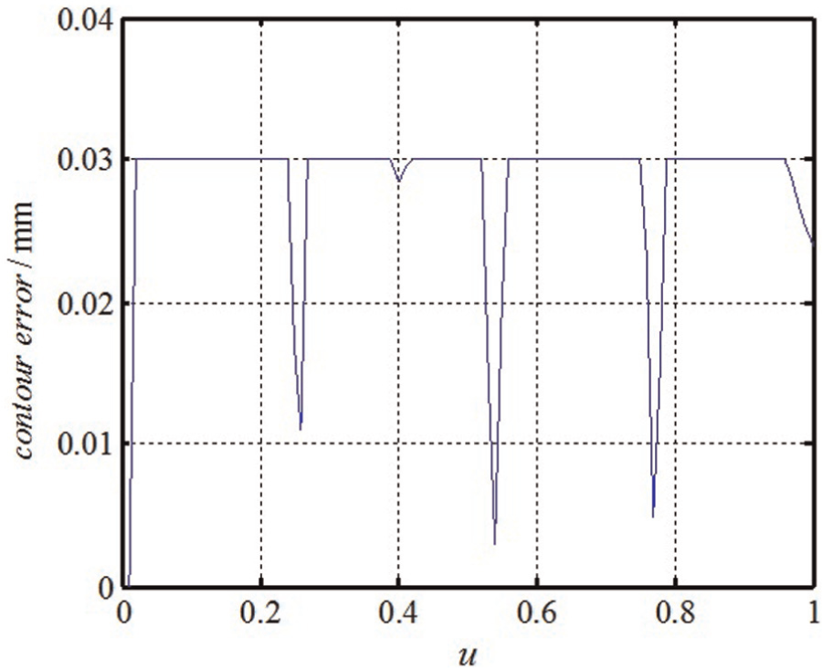
Curve of the contour error for the first test.
To demonstrate the effect of the motor torque constraint, a second test with
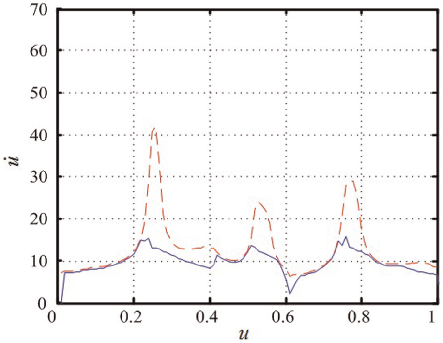
Results of the feedrate planning for the second test.
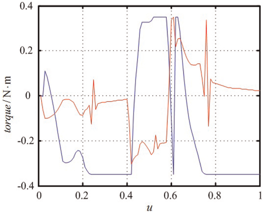
Curves of the motor torque for the second test.
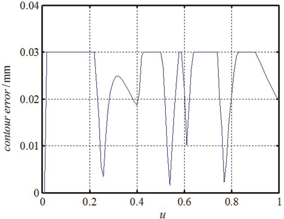
Curve of the contour error for the second test.
We choose the segment defined by
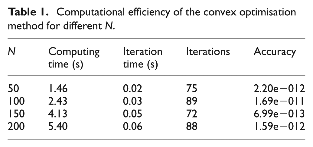
Finally, a computational efficiency test for the convex optimisation method was performed for different scales, denoted by
Computational efficiency of the convex optimisation method for different
Conclusion
In this article, complex constraints in a practical environment for HSM, including the motor torque constraint, the contour error constraint, the friction error constraint, the instruction velocity constraint and the smooth velocity constraint, are investigated in terms of time-optimal feedrate planning. An efficient convex optimisation method is then developed to solve this feedrate planning problem. The experimental results from two feedrate planning tests and a computational efficiency test show the validity, stability and high efficiency of the proposed convex optimisation method with complex constraints. Future work will address other constraints, such as the cutting force in the machining process, in addition to the constraints mentioned here.
Footnotes
Declaration of conflicting interests
The authors declare that there is no conflict of interest.
Funding
The authors would like to thank the China Postdoctoral Science Foundation (2014T70073, 2012M510423) and the National Key Science and Technology Project of China (2011ZX04004-012) for providing financial support for this research.