
Abstract
Tube hydroforming is a special manufacturing process that uses high-pressure fluid to flow the material into a die cavity. This process has been used mostly in automobile and aerospace industries. Compared to the conventional metal forming processes, it has the advantages of weight reduction, less tooling cost, fewer secondary operations, and improved structural strength and stiffness. In special working environments, multi-layered tubes with combined material properties, high strength, and corrosion resistance are required to satisfy conflicting requirements. In this study, an analytical model for predicting the forming pressure range of a three-layered tube is developed and experimentally verified. Fundamental theories for calculation of the pressure for the inner, center, and outer tubes are proposed. Forming pressures are obtained from equilibrium equations for the action and reaction forces on the contacting walls of the tubes. In order to validate the proposed model, free bulge experiments are performed with stainless steel/aluminum alloy/copper alloy and stainless steel/carbon steel/copper alloy three-layered tubes. The measured forming pressures are in reasonable agreement with those obtained from the analytical model.
Introduction
Tube hydroforming (THF) is a manufacturing process in which fluid pressure is applied into the metallic tubular parts to form desired component shapes in a closed die. 1 THF has emerged as a desirable manufacturing process in automobile and aerospace industries due to its ability to create a complex shape in a single step. 2 THF process has also proved to be a successful forming technology, replacing conventional stamping and deep drawing processes due to cost savings in terms of the elimination of die sets, reduction in assembly operations via parts’ consolidation, tight dimensional tolerances, and complex parts’ formability. 3 With the proper material selection and process design, the final component can be successfully manufactured using the hydroforming process.
Single-layered THF has been studied and applied over the past decade. However, due to requirements for combined properties to satisfy conflicting requirements, the need for multi-layered tubes is increased.4–6 Multi-layered tubes offer essential advantages for industrial applications. A bi-layered tube can avoid accidents when leakage of the inner tube occurs in a piping system, thereby improving safety and reliability for short- and long-distance fluid transportation. 7
Liu et al. 8 studied the forming mechanism of hydroformed two-layered tubes, and theoretical equations for thin and thick-walled tubes were created. Islam et al. 9 verified and validated the hydroforming of a multi-layered tubular component and described the mechanical stresses in the formed product. Alaswad et al. 10 compared single- and bi-layered THF processes and investigated the geometrical factors, formability, and failure in bi-layered THF. Kim et al. 11 experimentally investigated the three-layered THF. Seyedkashi et al. 12 developed an analytical model for prediction of the needed internal pressure in hydroforming bi-layered tubes. An analytical approach to determine the onset of bursting failure in THF under combined internal pressure and independent axial feeding has also been developed. 13 The stress-based hydroforming limit diagram obtained from their approach was experimentally verified. Yang and Ngaile 14 developed an analytical model that can be used to predict formed shapes, corner filling, wall thinning, and forming pressure based on deformation theory for planar THF.
The objective of this study is to develop an analytical model for predicting the forming pressure of a three-layered tube in a free bulging test. This model could be used as an initial estimation of the yielding and bursting pressures to define the forming pressure range as an input value for further finite element (FE) simulations and process optimization. To validate the model, experiments were performed at different internal pressures and feeding amounts.
Analytical model
As pressure is applied, the inner tube starts to expand and makes contact with the center tube at a specific pressure. This produces a mutual force and causes the center tube to expand to the internal surface of the outer tube. After full contact, all three tubes deform simultaneously. The deformation behavior of the three-layered tube can be assumed to be similar to the hydroforming of a single-layered tube for simplicity.
Fundamental equations based on an axisymmetric free bulging process are proposed for the three tubes, and the forming pressure is predicted using the equations. Using membrane theory, the internal pressure in a single-layered tube is associated with axial and hoop stresses. As shown in Figure 1, the behavior can be described using the following equation
Stress–strain conditions in a single-layered tube.
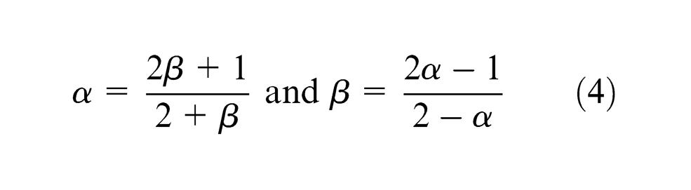
The stress ratio α and strain ratio β are defined, respectively, as
The principal strains at the end of the process are defined as
The strains in equation (3) are true strains and are used in the plastic mode. According to the Levy–Mises flow rule, stress and strain ratios are related as follows
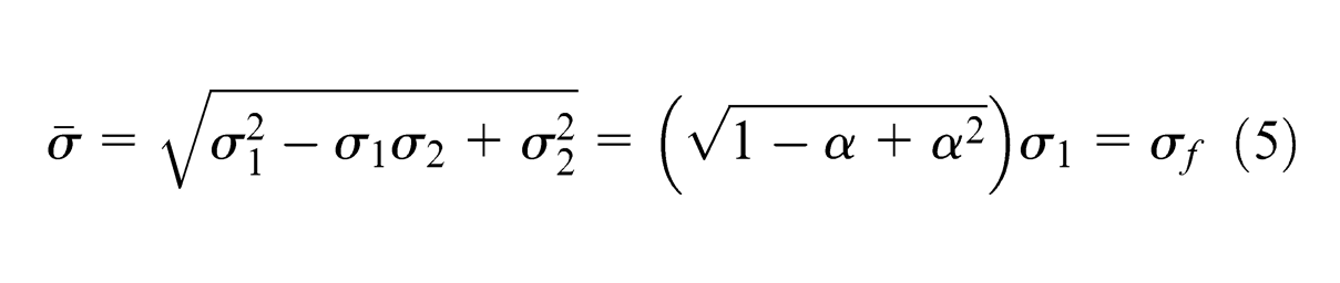
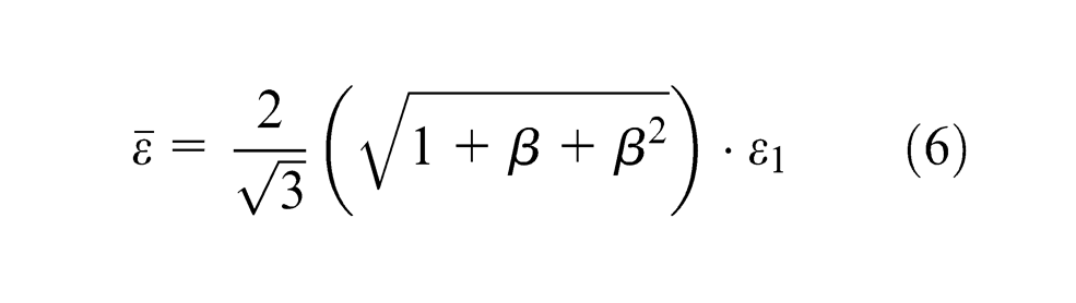
The von Mises yield criterion and its equivalent strain can be written as follows
Combining equations (1), (2), and (5)
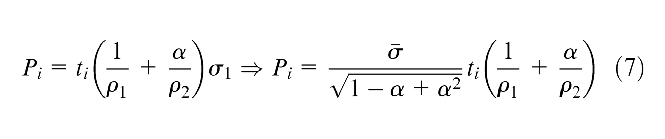
For analysis of the three-layered tube, the following assumptions were made. As shown in Figure 2, Pf is applied inside the inner tube. The inner tube starts to expand and contacts the center tube, which produces the contact pressure Pic. Pco is also caused by the contact of the center and outer tubes. Thus, for the outer tube, the actual pressure is Pco. For the center tube, the actual pressure is Pic − Pco. For the inner tube, the actual pressure is Pf − Pic. 12
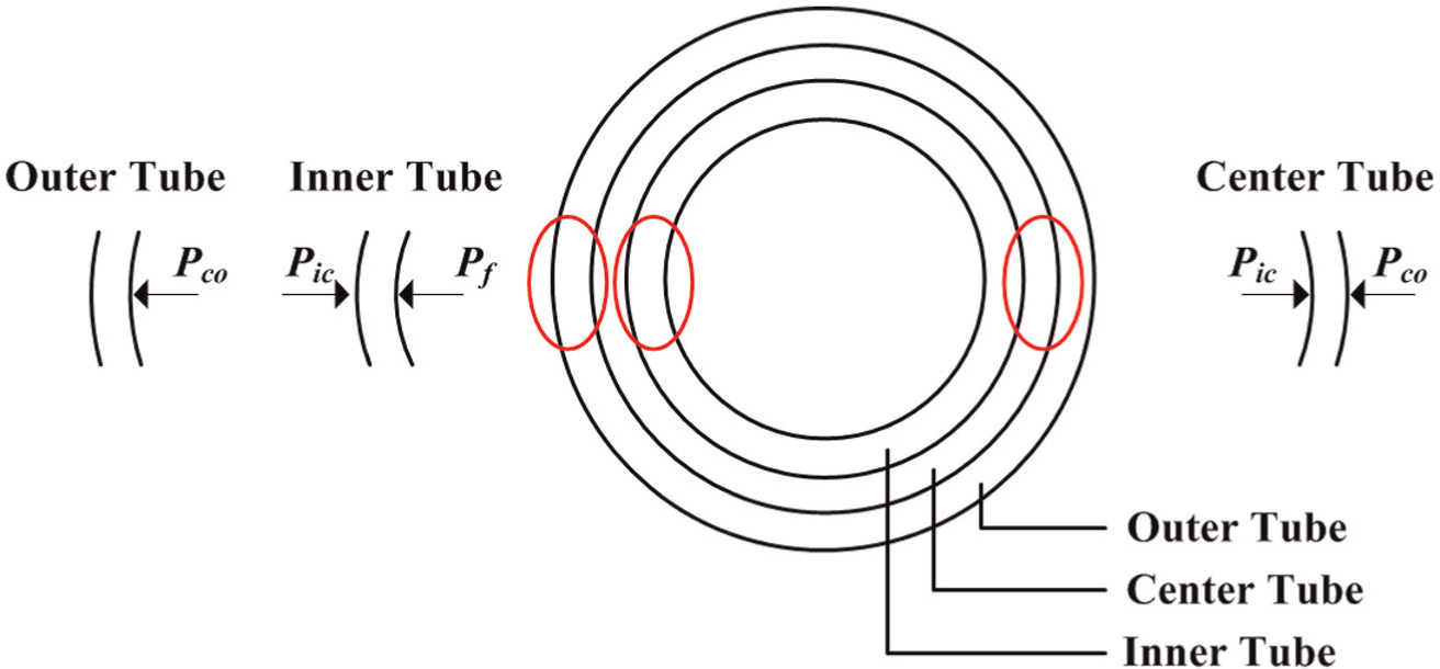
Pressure conditions for inner, center, and outer tubes.
To obtain the accurate forming pressure as shown in equation (7), the minor (ρ1) and major (ρ2) curvature radii need to be calculated. To determine the relationship between the minor curvature and major curvature radii of the final bulged product, an FE simulation of a three-layered tube was carried out using eta/DYNAFORM 5.5 in combination with LS-DYNA, which was used as a preprocessor to define the input parameters for the hydroforming process. The FE model was built in five parts: (1) outer tube, (2) center tube, (3) inner tube, (4) die, and (5) punch. By taking advantage of symmetry, only 1/8th of the structure was modeled to reduce the simulation time, as shown in Figure 3. The die and the punch were not fully modeled, and only the surfaces in contact with the layers were modeled using shell elements. The tubes were meshed using the Belytschko–Tsay quadratic element formulation. A power law isotropic plasticity formulation was used as the material model for the simulation. The nodes at the symmetric edges were restrained in the appropriate directions and the nodes attached to the tube ends were kept free to allow axial movement. The interfaces between the tube and each die and the punch were defined as “forming one way surface-to-surface” contact algorithm.
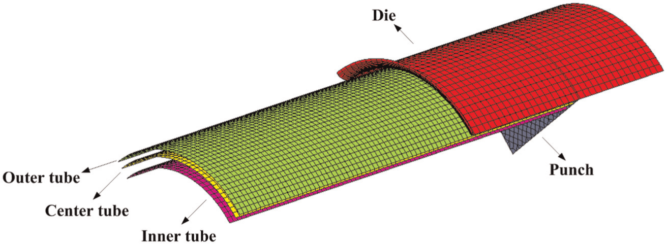
FE model of three-layered tube hydroforming.
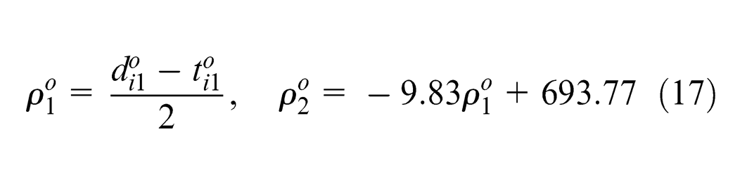
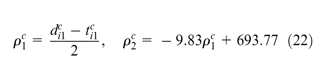
Two different combinations of tube dimensions were applied in the simulation. The profiles of the tubes in the hoop and axial directions when bursting occurred were assumed to be arc-shaped. The materials of the three tubes are stainless steel, carbon steel, and copper alloy. The minor curvature and major curvature radii of the final bulged products at various tube dimensions were measured (Figure 4) and summarized. A fitting line was created to describe the relation of ρ1 and ρ2, as shown in Figure 5. The mathematical relationship is
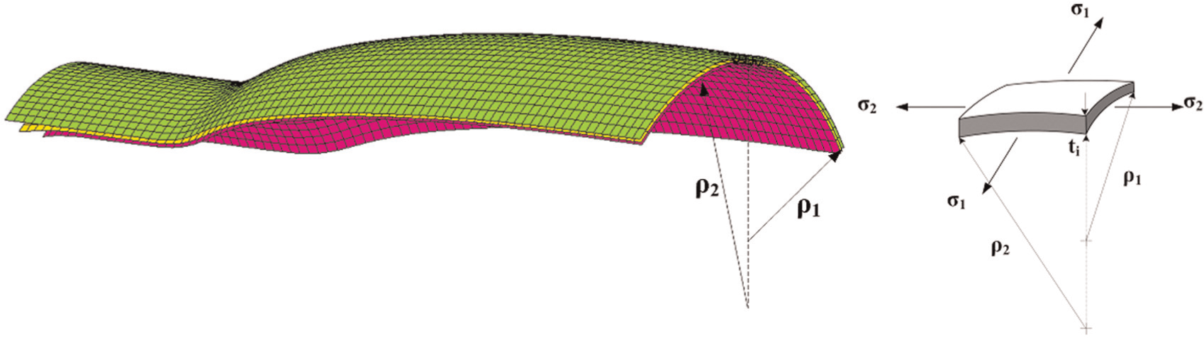
ρ 1 and ρ2 of final simulated product.
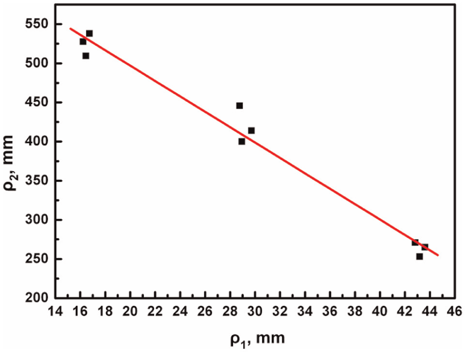
Relationship of ρ1 and ρ2 for final bulged product.
Prediction of the minimum pressure required to initiate hydroforming
To determine the minimum pressure needed to initiate hydroforming (yielding pressure), the tubes were assumed to be cylindrically shaped at the yield limit. Under the von Mises conditions, for the outer tube, tube conditions are given as
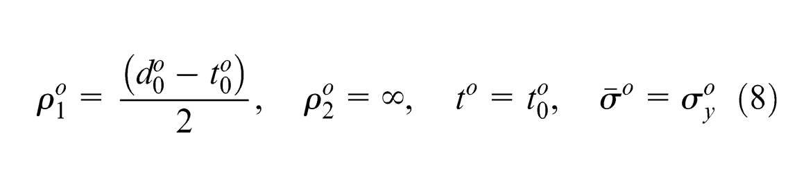
where
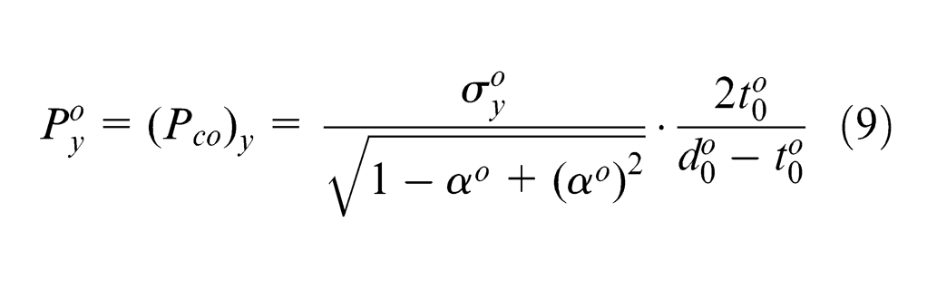
Combining equations (7) and (8)
At the yield limit, under von Mises conditions, for the center tube
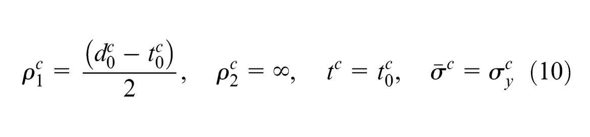
where
Combining equations (7) and (10) gives
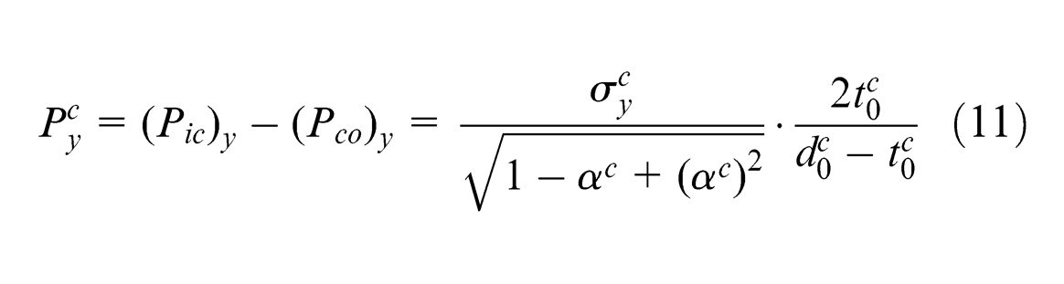
Combining equations (9) and (11)
At the yield limit, under von Mises conditions, for the inner tube
where
Combining equations (7) and (13) gives
Combining equations (12) and (14), the forming pressure to initiate hydroforming can be calculated as
Prediction of maximum pressure to avoid bursting
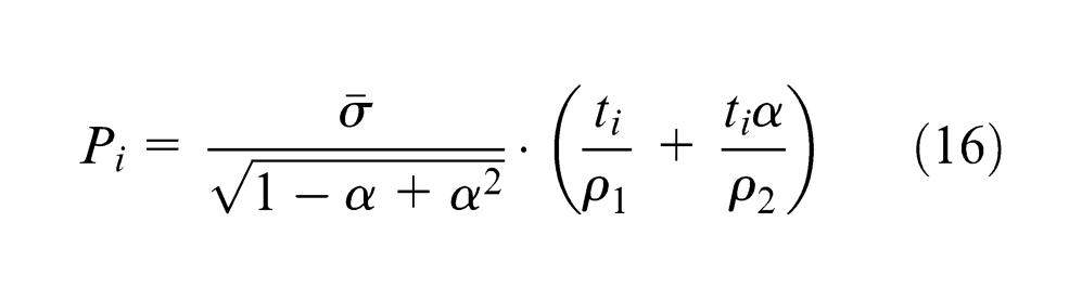
The tubes were assumed to expand in the shape, as shown in Figure 6. The hoop and axial profiles are assumed to be arc-shaped. With this assumption, the forming pressure equation is given by
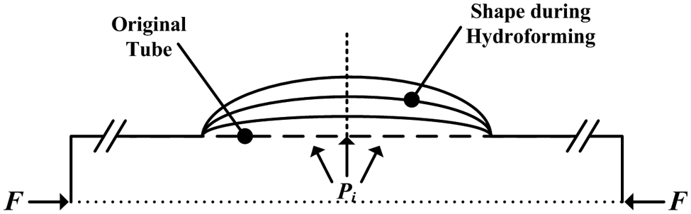
Deformation of tube in hydroforming process.
For the outer tube, the instantaneous radius is
For a small area unit of an element, it is assumed that
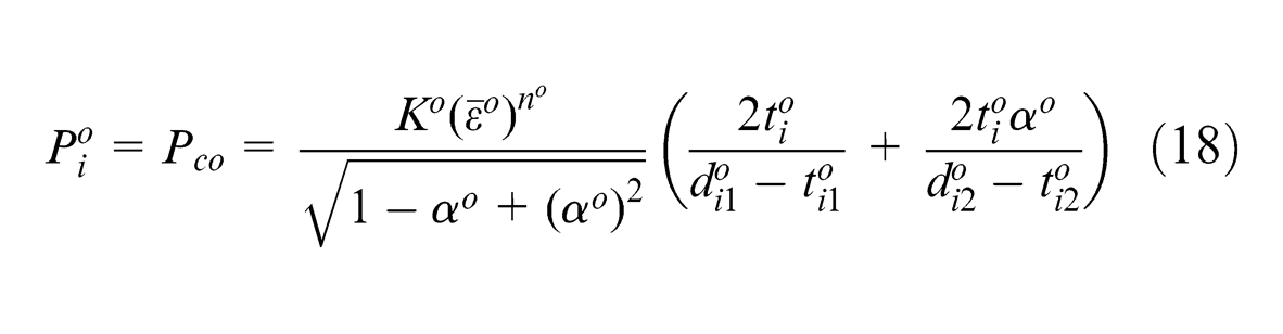
Based on equation (6), equation (18) can be modified as
According to equations (3) and (17)
Combining equations (4) and (20)
For the center tube, the instantaneous radius is
In a small area unit of an element, it is assumed that
According to equation (6), equation (23) can be modified as
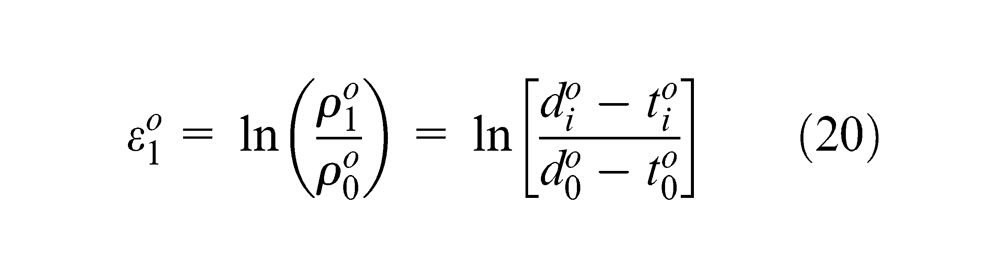
According to equations (3) and (22)
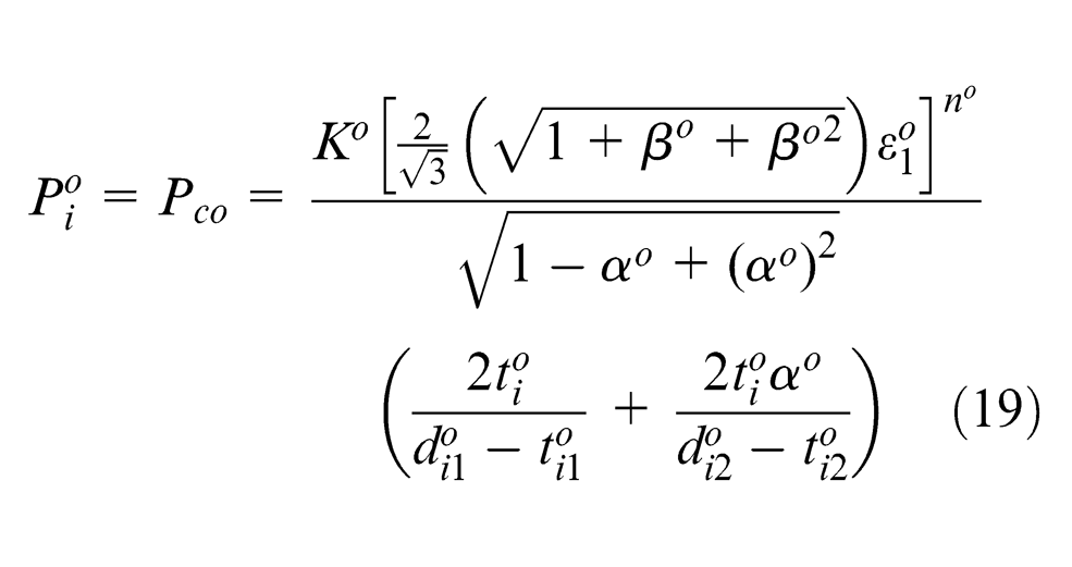
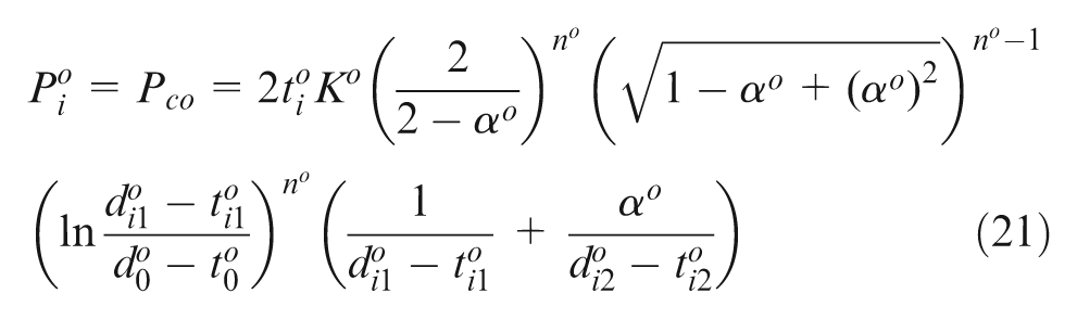
Combining equations (4) and (25) yields
Therefore, according to equation (26)
For the inner tube, the instantaneous radius is
In a small area unit of an element, it is assumed that
According to equation (6), equation (29) can be modified as
According to equations (3) and (28)
Combining equations (4) and (31)
Therefore
The pressure obtained using equation (33) is the final pressure needed for plastic deformation of the three tubes. To calculate
Analytical prediction of forming pressure
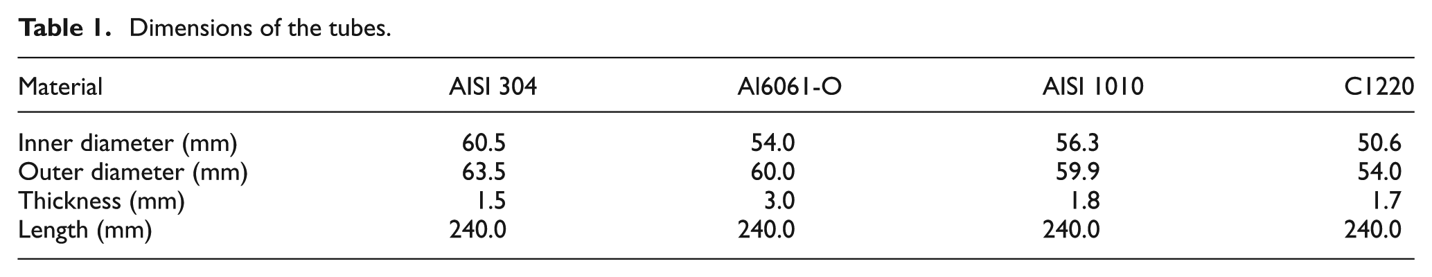
In order to validate the theoretical model, two cases of three-layered tubes were used in this study: (1) stainless steel (AISI 304)/aluminum alloy (Al6061-O)/copper alloy (C1220) and (2) stainless steel (AISI 304)/carbon steel (AISI 1010)/copper alloy (C1220), as shown in Figure 7. Table 1 shows the tube dimensions, and Table 2 shows the material properties obtained through a tensile test of a flattened part of the tube used in the experiments.
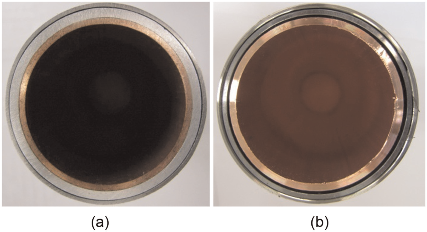
Three tubes used in the experiment: (a) Case 1: AISI 304/Al6061-O/C1220 and (b) Case 2: AISI 304/AISI 1010/C1220.
Dimensions of the tubes.
Material properties of the tubes.
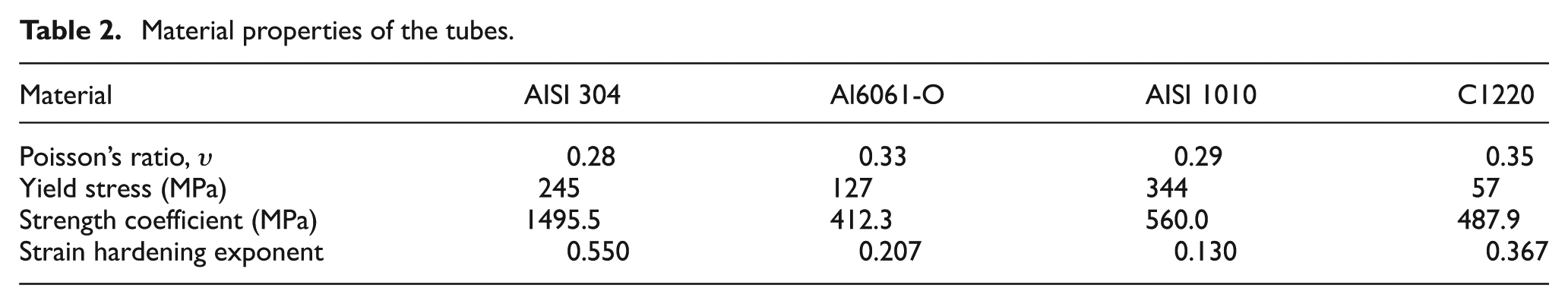
Figure 8 shows the predicted initiation and maximum pressures with respect to the stress ratio. It is seen that the minimum forming pressure was obtained in the pure shear state, whereas the maximum pressure was needed in the plane strain state. The pressure between the initiation pressure and maximum pressure can be applied as the forming pressure in three-layered THF.
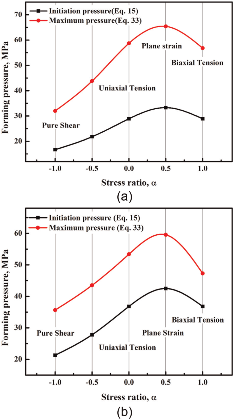
Forming pressure versus stress ratio: (a) Case 1: AISI 304/Al6061-O/C1220 and (b) Case 2: AISI 304/AISI 1010/C1220.
Experimental verification
The THF system was capable of applying preprogrammed paths of axial feed and internal pressure consisting of two 80-ton actuators mounted horizontally to supply the axial feed at both ends of a tube. A vertical hydraulic cylinder capable of delivering a clamping force of up to 80 tons provided the upper die movement. A pressure intensifier unit with a maximum capacity of 180 MPa was used to pressurize hydraulic fluid during the experiment, as shown in Figure 9.
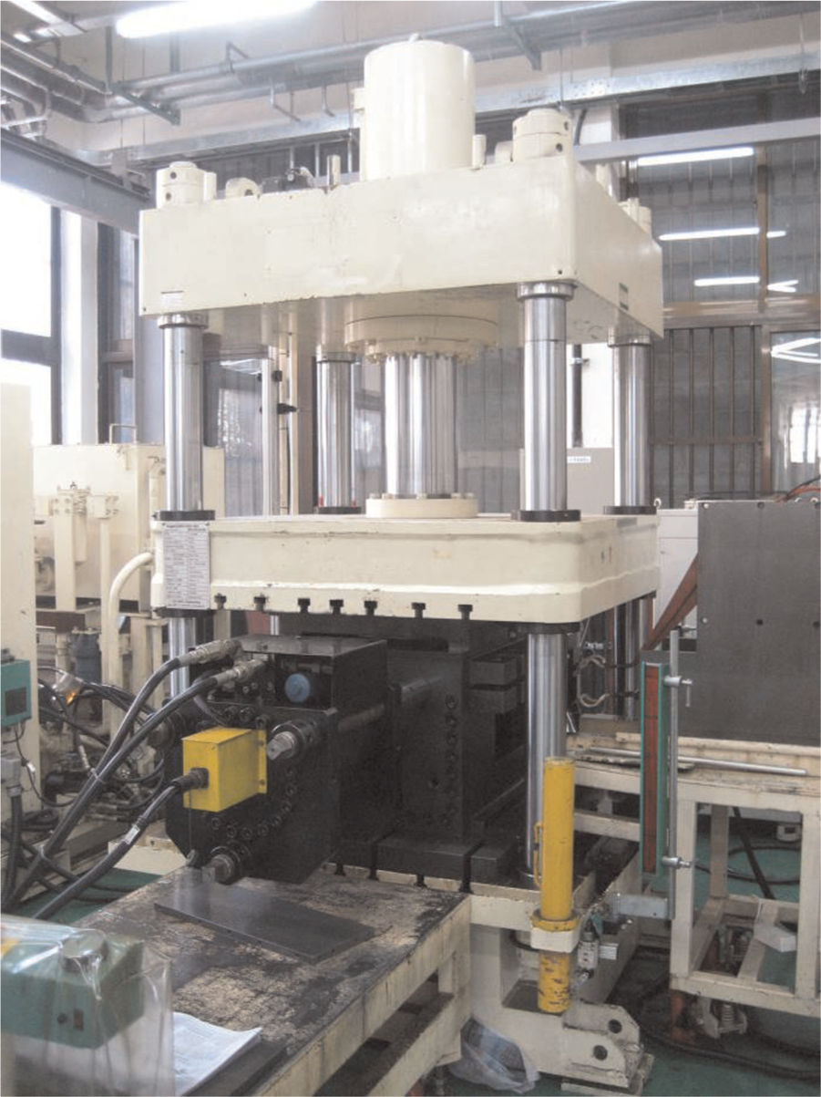
Tube hydroforming machine.
Figure 10 shows the final bulged products that were tested under experimental conditions. The internal pressure was increased until bursting occurred. The final geometric dimensions were substituted in the analytical equations, and the calculated pressures were compared to the final pressure obtained by experiments. For Case 1, the bursting pressures measured from four different three-layered tubes are 45.5, 46, 48.2, and 51.2 MPa, respectively. For Case 2, the bursting pressures of the different specimens are 48.3, 49.8, 51.4, and 55.2 MPa.
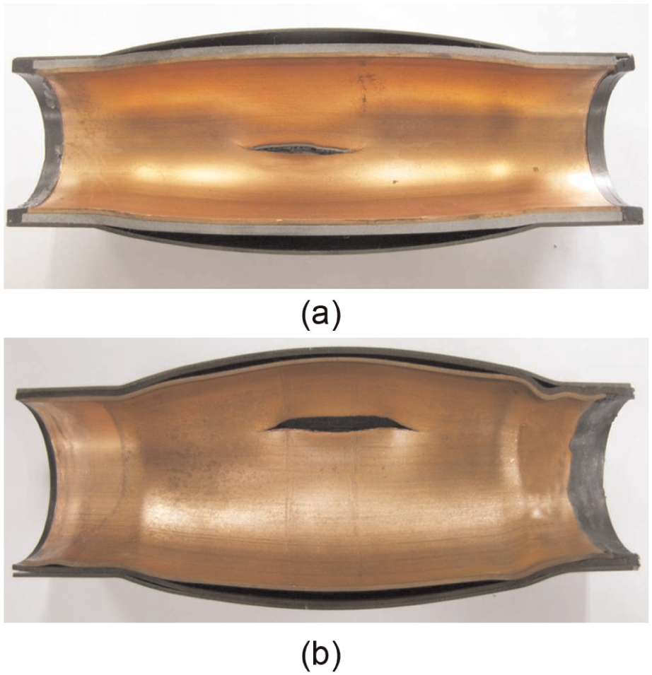
Bursting of final products in the experiment: (a) Case 1: AISI 304/Al6061-O/C1220 and (b) Case 2: AISI 304/AISI 1010/C1220.
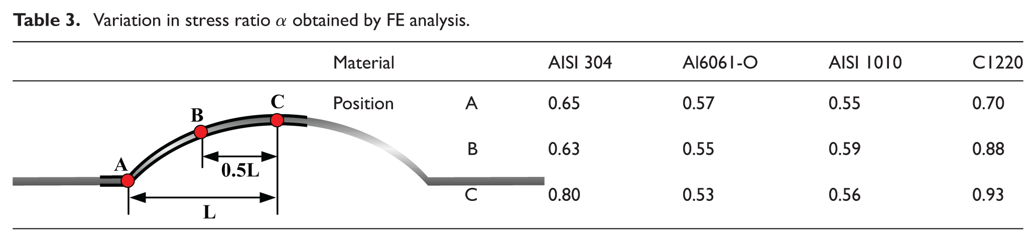
Figure 11 shows measured pressures from hydroforming experiments and analytically obtained pressures. As shown in Table 3, the values of stress ratio α obtained by FE analysis when the bursting starts lies in the range of 0.5 < α < 1; thus, the measured pressures were compared with analytical pressures obtained in the same α range. As shown in Figure 11, the measured pressures exceeded the hydroforming initiation pressure in both cases, which means that equation (15) (prediction of minimum pressure to initiate hydroforming) is reliable in terms of predicting the initiation pressure. There is some difference between the experimental forming pressure and theoretical bursting pressure in Case 1. Based on previous experience of the authors, this difference might be caused by the poor expansion ability of the Al6061 layer. The liquid medium filled inside the internal surface of the outer tube after the bursting of the inner and center tubes, and clearance existed between the center and outer tubes when the bursting of the outer tube occurred. The diagram for Case 2 shows that the experimental bursting pressure is in reasonable agreement with the theoretical bursting pressure obtained using equation (33) in the range from 0.5 < α < 1, which means that equation (33) (prediction of the maximum pressure to avoid bursting) is reliable in terms of predicting the maximum forming pressure. It can be conclude that a three-layered tube can be successfully formed using pressure between the initiation pressure and maximum pressure.
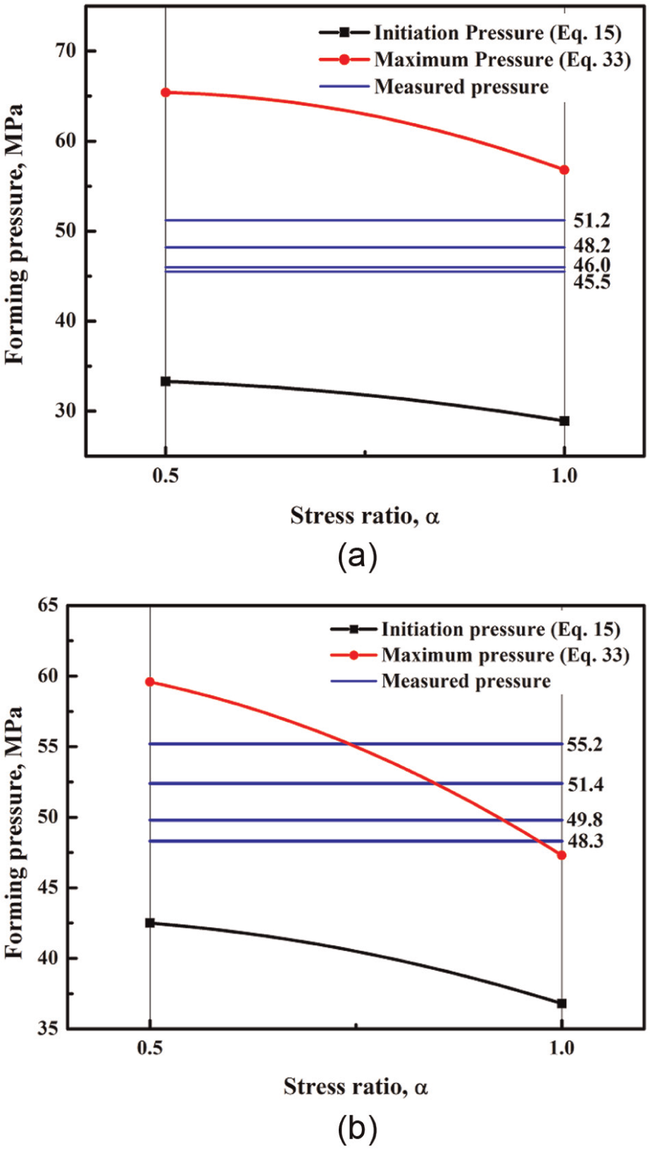
Effect of stress ratio on forming pressure: (a) Case 1: AISI 304/Al6061-O/C1220 and (b) Case 2: AISI 304/AISI 1010/C1220.
Variation in stress ratio α obtained by FE analysis.
Conclusion
In this study, the free bulging behavior of a three-layered tube was analytically investigated and experimentally verified. The calculated pressures were compared with experimental results. It showed that the measured bursting pressures are in reasonable agreement with those obtained from the analytical model, and that pressure between the initiation and maximum pressure can be applied as the forming pressure in three-layered free bulging. Actual tube sizes for other applications maybe different than those used in our investigation. However, fundamentally, the proposed analytical model can be applied to other three-layered tube free bulging applications.
Footnotes
Appendix 1
Declaration of conflicting interests
The authors declare that there is no conflict of interest.
Funding
This work was supported by the National Research Foundation of Korea (NRF) grant funded by the Korean government (MSIP) (no. 2012R1A5A1048294).