
Abstract
Friction-stir welding has emerged as an effective technique for the challenging task of welding aluminum alloys. This article presents a detailed experimental study on underwater friction-stir welding of 5083 marine-grade aluminum alloy. The effects of submersion, rotational speed, and translational speed were investigated. The thermal histories, void fractions, microhardness, and tensile properties of the welded alloy samples, as well as power consumption of the process, were measured and analyzed. The results showed that underwater friction-stir welding produced good tensile properties and led to a significant reduction in the void fraction.
Keywords
Introduction
Marine-grade aluminum alloys are specially designed alloys that contain 3%−5% magnesium and are known to be very resistant to corrosion by seawater, which makes it ideal for marine applications. Similar to welding other aluminum alloys, welding marine-grade aluminum alloys can be challenging because of their high thermal conductivity and low melting temperature. Although some conventional welding techniques could be used to weld aluminum alloys, some applications require the alloys to be welded underwater, which is very difficult and costly when these techniques are used. One welding technique that shows high potential in underwater welding is friction-stir welding (FSW). FSW is a relatively new welding technique introduced by The Welding Institute in 1991. 1 It uses a specially designed tool that consists of a pin and a shoulder. While the tool rotates, the shoulder rubs the alloy surface, generating enough heat to soften the material underneath, which allows the pin to stir the softened material and create a weld through plastic deformation. Unlike other welding techniques, FSW can be performed on samples submerged in water using the same procedure for in-air welding.
Many studies have investigated the effects of FSW and friction-stir processing (FSP) parameters on the resulting microstructure and mechanical properties of different alloys.2–7 Some researchers focused on studying the effects of thermal boundaries on the process. Upadhyay and Reynolds 8 compared the effect of thermal boundaries by FSW AA6063 samples in air and underwater. Submerged friction-stir welding (SFSW) results in a decrease in the average grain size owing to the higher cooling rates of samples that are welded underwater, as shown by the results presented by Fu et al. 9 In addition, the faster cooling rate in SFSW results in an increase in hardness measured at the stir zone and the heat-affected zone, while the hardness profile remains the same as that of a sample that was friction-stir welded in air. Liu et al. 10 also achieved similar results in terms of increased tensile strength of SFSW samples; however, it was noted that the plasticity of the samples deteriorated.
Zhang et al. 11 studied the effect of rotational speed on SFSW of AA 2219-T6. Mofid et al. 12 investigated the effect of submersion conditions in water and liquid nitrogen on the grain refinement in dissimilar welds. In their study, aluminum and magnesium plates were submerged and friction-stir welded; the results suggested that SFSW stopped the formation of brittle interatomic compounds in the weld, which the authors attributed to the lower temperature attained when the samples were submerged. Kim et al. 13 and Leal and Louriero 14 studied the formulation of defects in FSW samples. They reported that at a lower rotational speed, the material was not heated adequately, which caused the formation of a cavity or a groove-like defect. In contrast, at a relatively high rotational speed where excess heat was applied on the specimen, material was ejected outside the stir zone. Klobčar et al. 15 studied the effect of heat input on FSW of AA5083 by varying the rotational speed and feed rate. They concluded that higher hardness values were achieved at lower heat input owing to the smaller grains. Liu et al. 16 investigated the homogeneity of the material that was friction-stir welded underwater and in air. Underwater FSW and in-air FSW achieved very close tensile strengths in the upper layer of the alloy, while underwater FSW attained a significant increase in tensile strength compared to in-air FSW in the middle and lower layers, leading to better homogeneity of the mechanical properties in the welded material.
The effect of immersion conditions on the resulting microstructure and mechanical properties of an ultrafine-grained Al alloy after FSW was experimentally investigated by Hosseini and Danesh Manesh. 17 Their study showed that finer grains were attained in the stir zone by immersion, which led to less softening and noticeable improvement in the strength of the weld. A study by Hofmann and Vecchio 18 proved that submerging the sample could result in ultrafine grains because of the faster cooling rate. These findings were achieved using a modification of FSW known as FSP. In our previous study, 19 submerged FSP of AZ31 magnesium alloy was investigated, and we studied the effects of the immersion medium’s temperature on the resulting grain size and tensile properties of the FS-processed magnesium samples. The results indicated that cold water led to more grain refinement, while better tensile properties were obtained when hot water was used.
In this study, marine-grade aluminum alloy 5083 was friction-stir welded while it was submerged. As this alloy is heavily used in marine applications, the quality of underwater friction-stir welds was investigated and compared to that of in-air friction-stir welds. We also conducted a comprehensive experimental investigation on the effects of welding parameters on the resulting tensile properties, microhardness, microstructure, and power consumption.
Experimental details
The material used in this study was 5083 marine-grade aluminum alloy in the form of 4-mm-thick sheets. Each sample was 130 mm long and 60 mm wide. The chemical composition of AA5083 is given in Table 1. The tool used in this study had a featureless shoulder with a 15-mm diameter and a threaded pin with a length and diameter of 4 and 5 mm, respectively. FSW and SFSW were conducted using a vertical computer numerical control (CNC) machine. The aluminum sample was clamped onto a container that was specially designed for submerging the sample. Tap water at room temperature was used for the submersion. After FSW and SFSW of the sample, we obtained tensile specimens transverse to the weld direction, in addition to smaller samples for microstructural investigations, as shown in Figure 1.
Chemical composition of 5083 aluminum alloy (wt%).
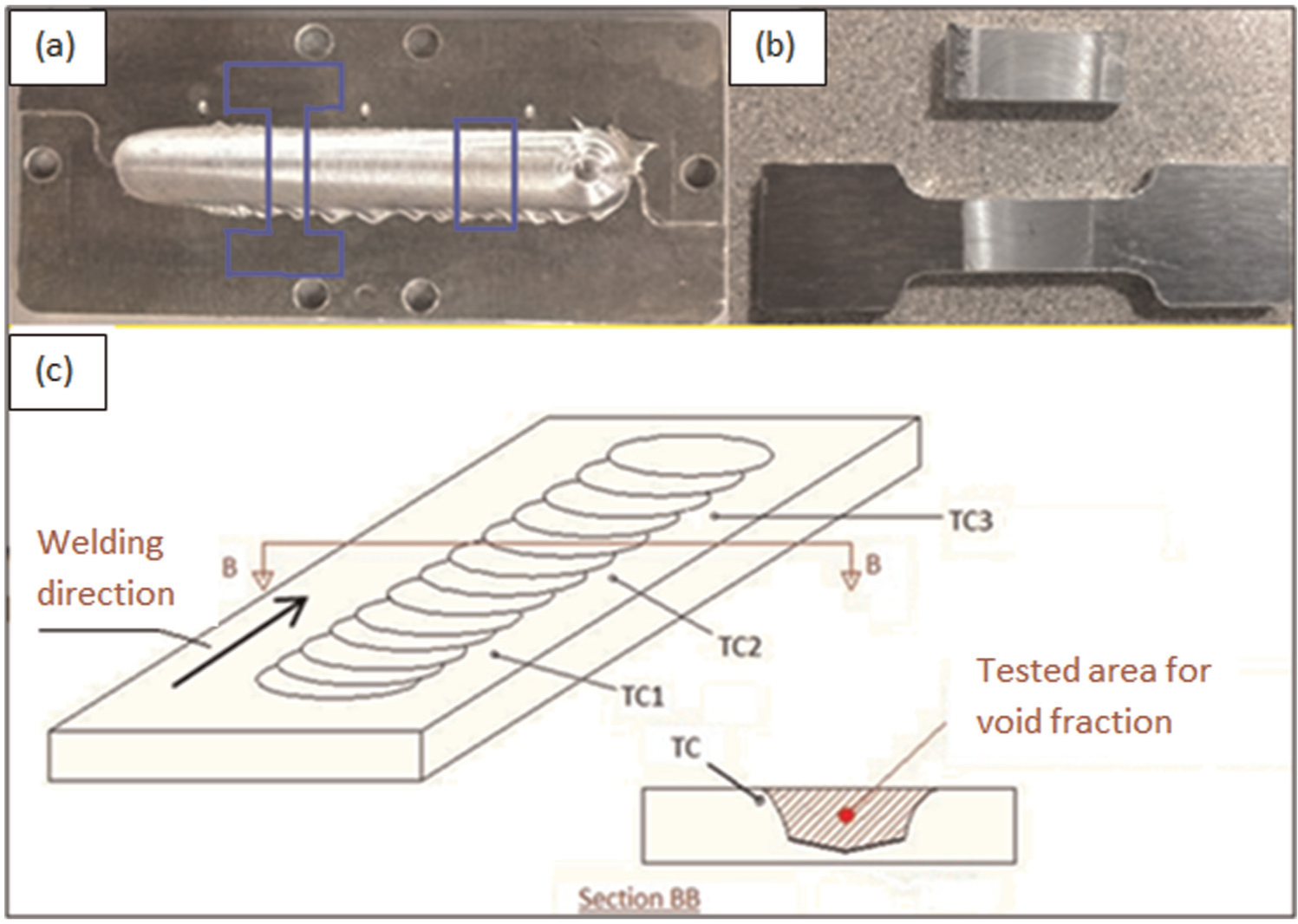
(a, b) Tensile and microstructural test specimens (c) positions of thermocouples TC1, TC2, and TC3 in a sample.
During FSW and SFSW, the temperature was measured at three different locations using K-type thermocouples. The three thermocouples were located 3 mm away from the stir zone and 1 mm from the top surface of each sample, as shown in Figure 1. The tensile tests were conducted using an Instron universal tensile testing machine at a speed of 2 mm/min. To ensure the accuracy and reliability of the experimental results, all tests were conducted under the same conditions. The microhardness was measured using a QV-1000DM (Qualitest, USA) digital microhardness tester, a load of 1000 g, and a dwell time of 10 s. The microhardness readings were taken in the middle of the stir zone and 1 mm from the top surface for all samples. The microhardness of one FSW sample and one SFSW sample was measured along the transverse surface of the weld. The average of four readings was used for each microhardness data point except for the transverse profile, where each data point represents a single reading. A PS3500 (Summit Technology, USA) power data logger was used to record the power consumption of the CNC machine during FSW and SFSW.
Results and discussion
Rotational speeds ranging from 800 to 1200 r/min and feed rates ranging from 25 to 100 mm/min were used for in-air FSW. The rotational speed was then increased to 2000 r/min for SFSW, as the samples at relatively low speed were defective because of insufficient heating. Figure 3 shows a comparison of three samples: one FSW sample and one SFSW sample prepared at the same rotational speed and feed rate; one SFSW sample prepared at a higher rotational speed. The sample in Figure 2(a) displays the effect of insufficient heating during SFSW: the material was not stirred properly as it was not softened enough owing to the small amount of heat applied. Figure 2(b) and (c) shows samples produced by FSW at 1000 r/min and SFSW at 1700 r/min, respectively. During in-air FSW, a rotational speed of 1000 r/min applied enough heat to soften and properly stir the material, while SFSW required a rotational speed of 1700 r/min to produce a good-quality weld.
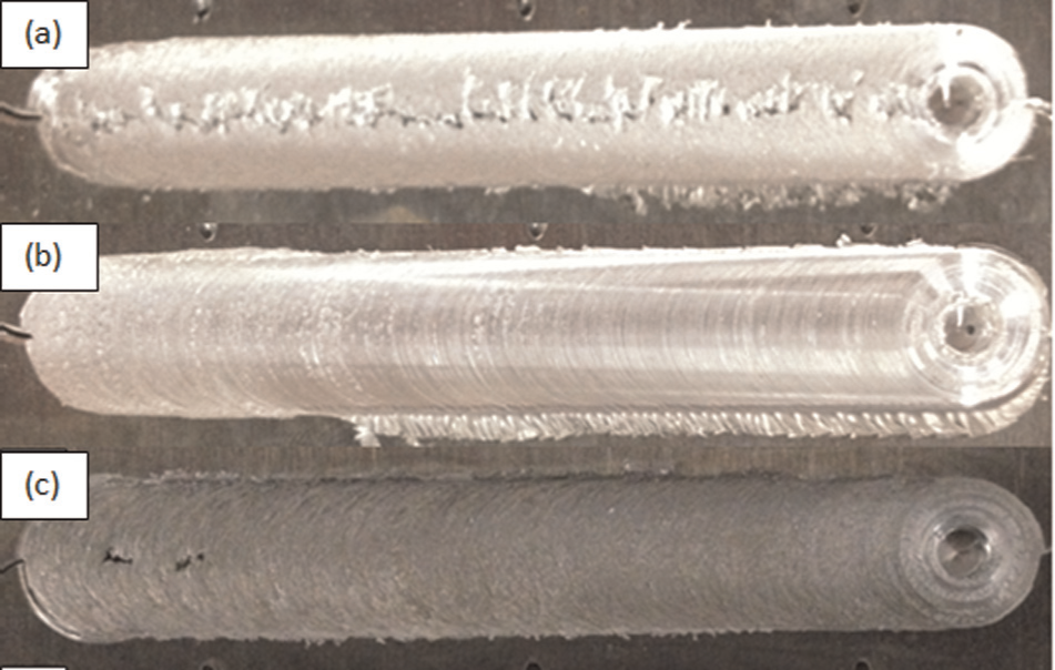
Weld samples produced by (a) SFSW at 1000 r/min, (b) FSW at 1000 r/min, and (c) SFSW at 1700 r/min.
Temperature
As FSW is a thermomechanical process, it is essential to understand the thermal aspects of the technique. The heat exerted on the samples during FSW and SFSW has a significant effect on the microstructure, microhardness, and tensile properties of the welded product.19–22 The thermal histories presented in Figure 3 were used to view and compare the peak temperature reached when welding different samples, the cooling rate, and how long the temperature stayed above a reference point. The results presented in this section were used to examine the effect of different process parameters on the resulting microstructure and mechanical properties.
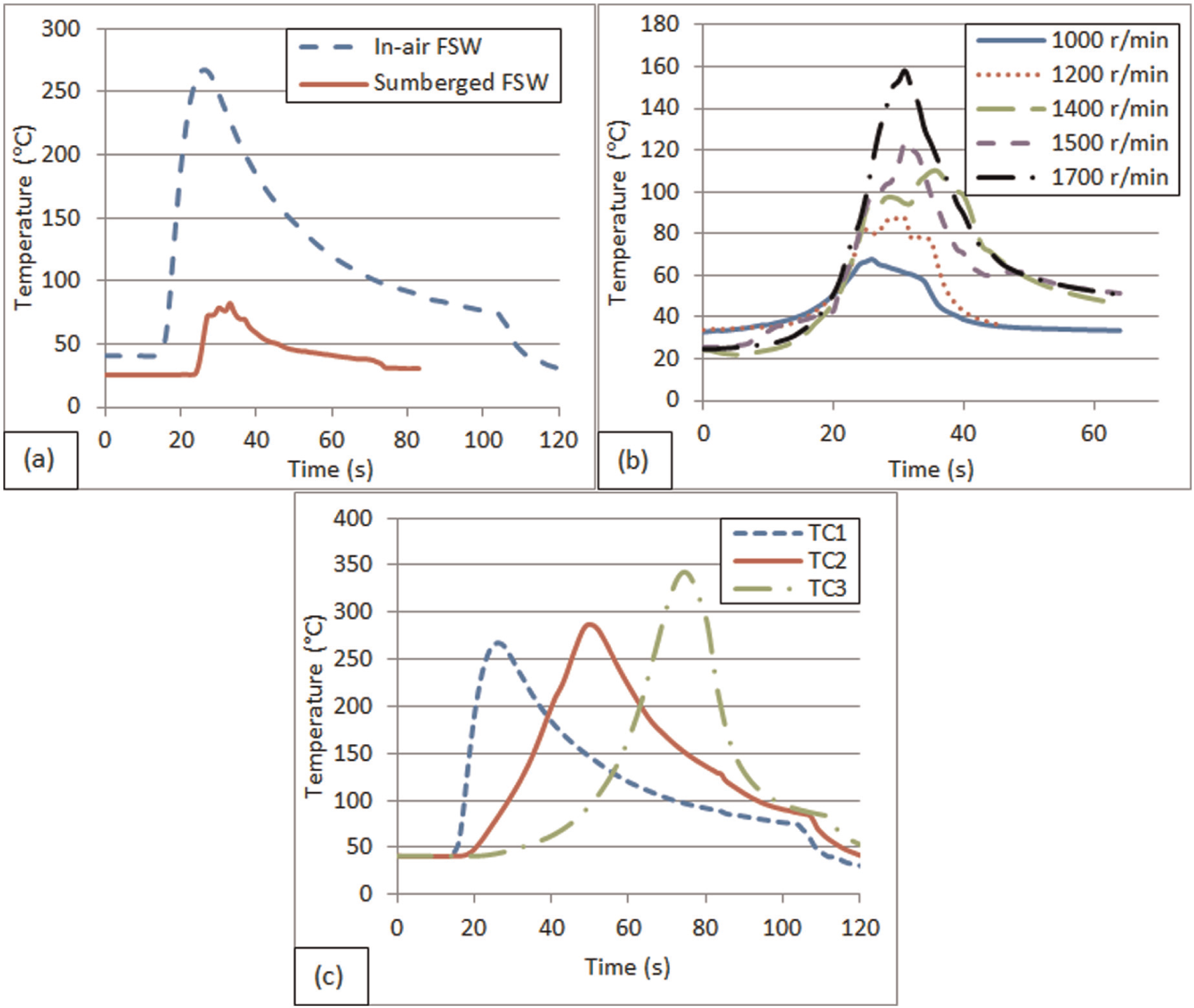
Temperature profiles of samples prepared by (a) FSW and SFSW at 1000 r/min and 75 mm/min and (b) SFSW at different rotational speeds and 100 mm/min. (c) Temperature profiles at three longitudinal positions within a welded sample.
Controlling the heat input to the weld is a very crucial step. We need to generate enough heat to soften the material while limiting significant grain growth, thus affecting the resulting mechanical properties of the weld. Figure 3(a) shows the thermal histories of two samples: one welded in air and the other while submerged; constant rotational speed and feed were used for both samples. For SFSW at 1000 r/min, the heat input to the weld was not even enough to soften the material, producing the defective weld shown in Figure 2(a). It is also clear that the SFSW sample experienced a very low peak temperature and a higher cooling rate compared to the FSW sample. This can be explained by the higher heat capacity of water compared to air. 18 The results are in agreement with those from our previous study, 19 in which FSW of a sample submerged in hot or cold water resulted in a lower peak temperature and a faster cooling rate. Figure 3(b) shows the effect of the rotational speed on SFSW: as the rotational speed increased, the peak temperature increased; however, there was no significant effect on the cooling rate of the samples.
In general, the cooling rate is mainly affected by the medium, be it air, water, or other coolants, as well as the time during which heat is applied to the weld, which is controlled by the feed rate. The increase in peak temperature is due to the increase in frictional heat and heat resulting from severe plastic deformation in the material, both of which increase with increasing rotational speed. The thermal profile also explains the formation of void defects owing to insufficient heating in SFSW at lower rotational speeds, where the material is not heated enough and thus not soft enough to be perfectly stirred.13,14
Figure 3(c) shows the temperature histories for three thermocouples positioned along the sample, as shown in Figure 1. An increase in peak temperature was measured by the thermocouples farther away owing to lateral conduction, which was boosted by the high thermal conductivity of the alloy. 21 As a result, changes to the uniformity of the weld’s microstructure and consequently its mechanical properties were expected (see the section on “Microhardness”).
Void-area fraction
Figure 4 shows optical microscope images of the parent material and an SFSW sample. Our results showed that the void-area fraction in the stir zone decreased significantly in all SFSW samples. A void-area fraction of 4.1% was estimated in the parent material, which was significantly reduced to as low as 1.3% in the stir zone when it underwent SFSW at 1700 r/min and 25 mm/min. All the other SFSW samples exhibited a decrease in average void-area fractions compared to the parent material. Not only was the void-area fraction reduced, the average size of the voids was also reduced by SFSW. Compared to an average void size of 38 µm in the parent material, a void with average dimensions in the range of 5–10 µm was observed in different SFSW samples prepared under various conditions. The reduction in void-area fraction and void size played an important role in delaying the cavity-induced failure during the plastic deformation of the material.
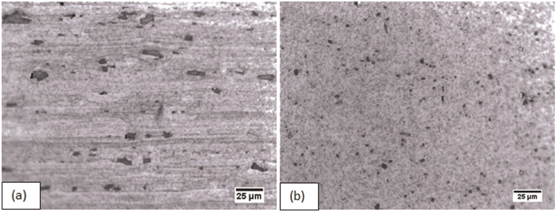
Optical microscope images showing voids in (a) unprocessed material and (b) an SFSW sample.
Microhardness
Figure 5(a) shows the hardness profiles of transverse sections of samples subjected to in-air and submerged FSW. The measurements were obtained at a depth of 2 mm from the top surface of the sample. The advancing side of the weld attained lower microhardness than the retreating side in all cases, which can be explained by the higher heat input on the advancing side. 15 It is known that hardness is directly related to the grain size and grains experience more growth with increasing temperature. At a constant rotational speed and feed rate, SFSW yielded higher hardness readings than FSW because of the lower peak temperature and higher cooling rate. The sample prepared by SFSW at 1000 r/min and 75 mm/min exhibited a maximum hardness of 121.6 HV, while the sample prepared by FSW at the same rotational speed and feed rate showed a maximum hardness of 89.6 HV, compared to an average hardness of 85.7 HV for the parent material. Variations in the microhardness throughout the thickness of the weld were also observed. As shown in Figure 5(b), the average microhardness increased with increasing distance from the top surface. Again, this can be explained by the top surface’s exposure to higher heat input, which led to more grain growth and consequently lower microhardness. Figure 5(c) shows the difference in microhardness measured along the weld line of the FSW sample. These results are in agreement with the thermocouple readings, which prove that the later part of the welding process attained higher heat input than the earlier part, as shown in Figure 3(c). The increase in heat input in the final part of the process led to a lower microhardness because of grain growth.7,23 The effect of rotational speed on the microhardness of the welded material is shown in Figure 5(d). In both FSW and SFSW samples, the increase in rotational speed caused an increase in the microhardness measured. This can again be attributed to the increase in heat input as the rotational speed increased. Grain growth occurred in the welded samples because of heat input, causing the microhardness to decrease as the grain size increased. 24
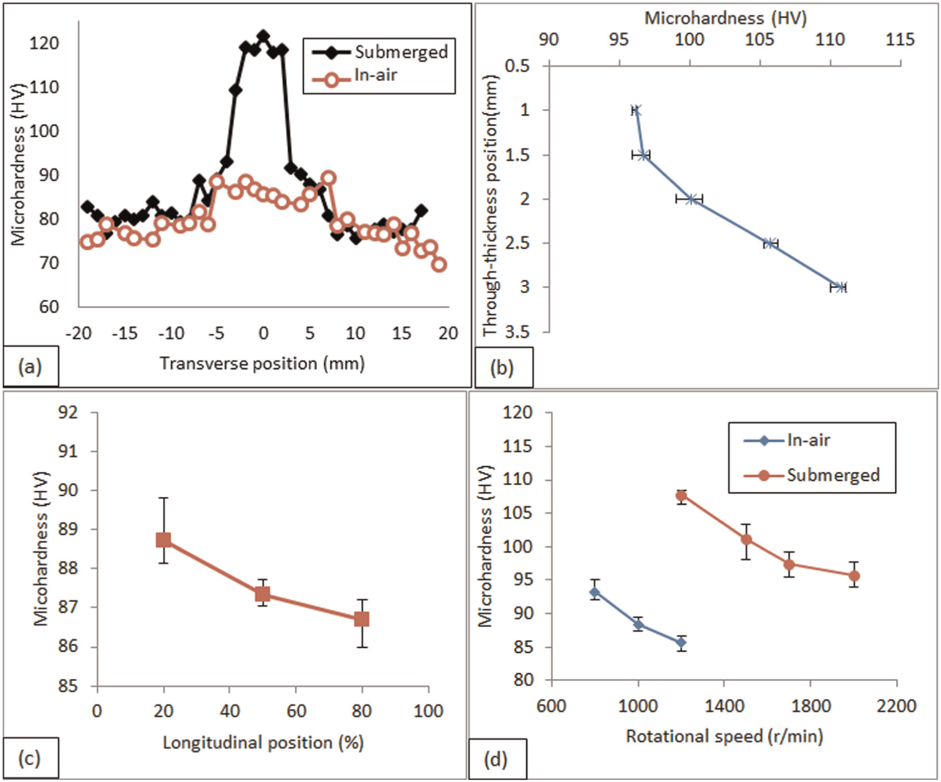
Microhardness at different positions and under different settings: (a) transverse sections of FSW and SFSW samples; (b) along the weld thickness; (c) along the weld; and (d) variation with rotational speed.
Tensile properties
Figure 6 shows the stress–strain curves of an unprocessed sample; FSW samples prepared at 1000 r/min and 75 mm/min; and SFSW samples prepared at a feed rate of 75 mm/min and rotational speeds of 1000, 1500, and 1700 r/min. As discussed in the previous sections, when the same conditions that produced a good weld in air were used for SFSW, a defective weld was produced because of insufficient heating. As a result, the tensile properties of the in-air FSW sample were significantly better than those for the SFSW sample prepared under the same conditions. When good-quality welds produced by both in-air FSW and SFSW were compared, clearly better tensile properties were attained in the SFSW samples, whose tensile strength was as high as 300 MPa compared to 315 and 240 MPa for theas-received material and the in-air FSW sample, respectively. The SFSW samples exhibited up to 32% elongation compared to the 16% elongation of the as-received material and the 27% elongation of the in-air FSW sample. The increase in rotational speed resulted in more proper stirring of the SFSW samples and thus better tensile properties. The improved mechanical properties attained with submersion are believed to be related to the microstructural changes (grain size, orientation, void evolution, etc.) resulting from the change in thermal boundaries. A lower peak temperature and a higher cooling rate led to less grain growth, and consequently, finer grain structure and better mechanical properties. Void evolution is believed to have played an important role as well. The lower void fraction and average void size in the SFSW sample probably delayed the cavity-induced failure during plastic deformation. The results are in agreement with previous studies in which submersion caused an increase in the cooling rate and led to better tensile properties.18,19 A summary of the tensile properties of all samples is presented as a bar-chart in Figure 7.
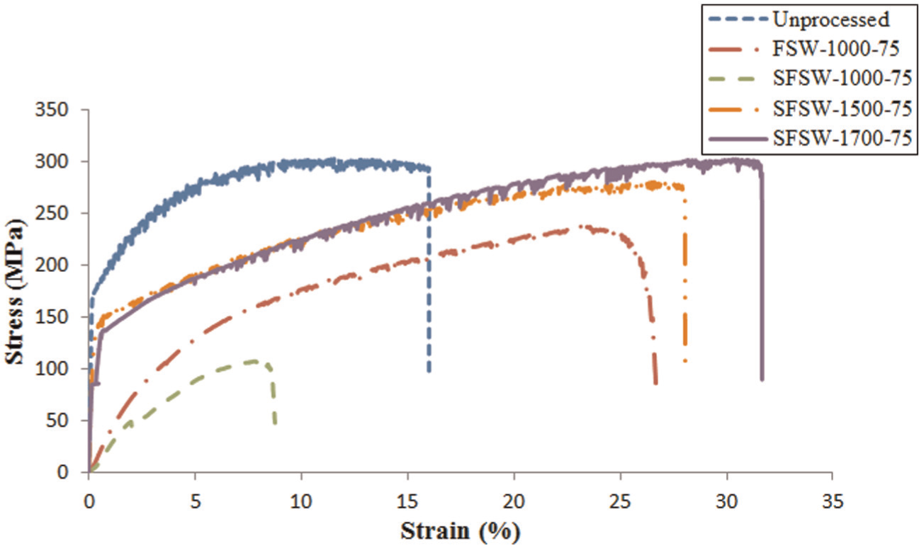
Stress–strain curves of unprocessed material and FSW and SFSW samples prepared at different rotational speeds.
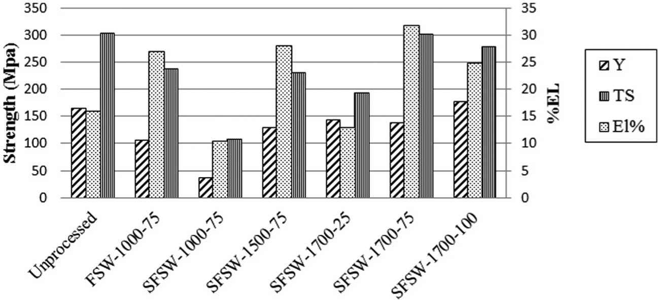
Tensile properties of unprocessed material and FSW and SFSW samples prepared under different conditions.
Power consumption
The power consumption of the CNC machine, shown in Figure 8, was directly related to the rotational speed of FSW. At the lowest rotational speed of 800 r/min, the average power consumption was 734 W; at the highest rotational speed of 1700 r/min, the average power consumption was 961 W. The recorded data also showed a direct effect of the submersion conditions on the power consumption. Nonetheless, as discussed earlier, extra heat input through an increase in the rotational speed was required to obtain good-quality welds in SFSW, which led to higher power consumption.
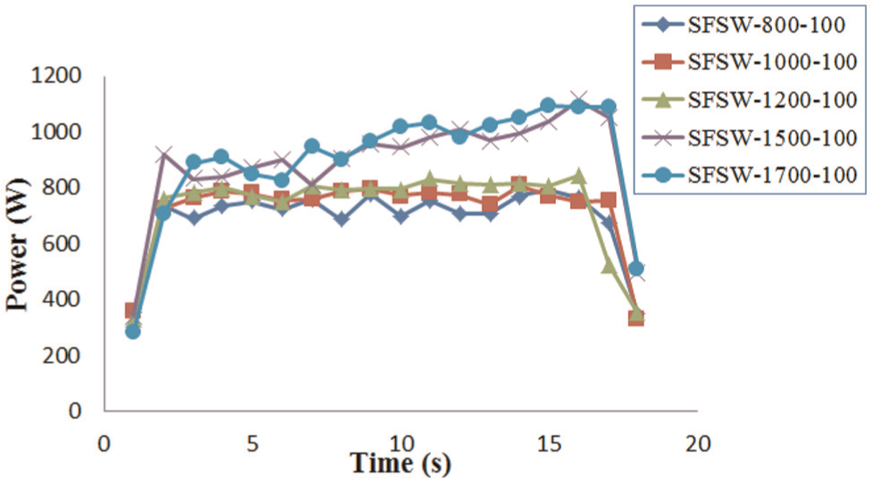
Power consumption of the SFSW process at different rotational speeds.
Conclusion
Marine-grade 5083 aluminum alloy samples were friction-stir welded in air and underwater. The effects of different process parameters on the temperature, void fraction, and mechanical properties of the welded samples were investigated. The results of this study led to the following conclusions:
Compared to in-air FSW, underwater FSW required higher rotational speed to produce high-quality welds because of the relatively high thermal capacity of water compared to air. Submerging the sample in water also caused a reduction in the peak temperature and an increase in the cooling rate.
Compared to the parent material, the void-area fraction decreased significantly in the stirred material in the SFSW sample. The estimated void-area fraction in the stir zone of the SFSW sample was almost one-third of that in the parent material.
A significant increase in microhardness was observed in the SFSW samples. The highest microhardness measured was in the stir zone, whereas the lowest was on the retreating side. The lower surface of the stirred material reached higher microhardness values than the top surface owing to heat transfer to the backing plate, which reduced the grain growth.
The tensile strength of the underwater FSW sample was very close to that of the parent material. The elongation of the SFSW sample increased to approximately twice the elongation of the parent material.
Footnotes
Declaration of Conflicting Interests
The author(s) declared no potential conflicts of interest with respect to the research, authorship, and/or publication of this article.
Funding
The author(s) disclosed receipt of the following financial support for the research, authorship, and/or publication of this article: This study was supported by the Emirates Foundation, Science and Engineering Research Grant No. 2010/117 and the College of Engineering at the American University of Sharjah.