
Abstract
High-speed grinding experiments of particle reinforcing titanium matrix composites ((TiCp + TiBw)/Ti-6Al-4V) were carried out with vitrified cubic boron nitride wheel and electroplated cubic boron nitride wheel, at the wheel speed ranged from 80 to 140 m/s. The cutting behavior, that is, grinding force, grinding temperature, specific grinding energy, and ground surface morphology, and grinding chips are analyzed. The results indicate that compared to the workpiece speed and the depth of cut, the wheel speed has a more significant influence on the grinding forces. The grinding temperature and specific grinding energy obtained with the vitrified cubic boron nitride wheel are always larger than those with the electroplated cubic boron nitride wheel. Based on the comprehensive consideration in terms of grinding force, grinding temperature, and specific grinding energy, the electroplated cubic boron nitride wheel is more suitable than vitrified cubic boron nitride wheel for high-speed grinding particle reinforcing titanium matrix composites. The removal of the reinforcements of particle reinforcing titanium matrix composites is mainly by means of pullout, fracture or crushing, micro-cracks, voids, and smearing. The segment chips containing the reinforcements are formed during high-speed grinding of particle reinforcing titanium matrix composites.
Keywords
Introduction
Particle reinforcing titanium matrix composites (PTMCs) (TiCp + TiBw)/Ti-6Al-4V, as the newly developed metal-matrix composites (MMCs), have a broad application prospect in the aerospace industry due to their excellent comprehensive mechanical properties in terms of high specific strength and high temperature durability.1–3 Similar to other particle reinforcing MMCs, that is, SiCp/Al and Al2O3/Al, the PTMCs are also typical difficult-to-cut materials because of the low plasticity, non-uniformity, and abrasive nature of the reinforcements. In particular, the defects are easily formed on the machined surface of PTMCs, which has a significantly negative impact on the mechanical properties of the machined component. 4 Consequently, how to minimize the disadvantageous effects, that is, rapid tool wear, low material removal rate, and poor machined quality during cutting PTMCs, has been an important issue in the materials processing field.
In the recent years, some research work on the machinability of particle reinforcing MMCs has been carried out. Huan et al. researched the tool wear behavior during turning and milling PTMCs.5–7 It was found that the carbide tool was not suitable for machining PTMCs, while the service life of polycrystalline diamond (PCD) was only confined to 12 min for all the cutting conditions. Severe abrasive wear and adhesive wear were the main wear mechanisms of the cutting tools. Similar results were obtained in the turning, milling, and drilling experiments of SiCp/Al composites by Muthukrishnan et al. 8 and Huang and colleagues.9,10 Bian et al. 11 carried out the precision milling of SiCp/Al composites. The primary tool wear pattern included chipping and cleavage on monocrystalline diamond edge. El-Gallab et al. studied the machined surface of SiC/Al particulate MMCs in the dry high-speed turning test. The grooves and holes were formed due to the pullout of SiC particles. 12 Zhong and Hung investigated the grinding process of aluminum-based MMCs reinforced with Al2O3 particles using vitrified SiC grinding wheel and resin-bonded diamond grinding wheel. The smearing of aluminum on the ground surfaces was observed for rough grinding, but was negligible for fine grinding. 13 Blau and Jolly 14 found that the particles were fractured and pulled out, with some clusters of fragments remaining on the surface or trapped in cracks occurred during the conventional speed grinding tests of titanium-based MMCs. This indicates the difficulty to cut the particle-reinforced MMCs.
High-speed grinding with cubic boron nitride (CBN) abrasive wheels has been regarded as one of the most effective means to machine difficult-to-cut materials.15–18 It is reported that the increase in wheel speed in the high-speed grinding reduces the undeformed chip thickness, thus resulting in a desirable control of force and temperature.19,20 Moreover, the ductile removal mode of the brittle reinforcements perhaps takes place during the high-speed grinding processes. 21 As a result, high-speed grinding can not only improve the machining efficiency but also suppress the formation of the machined effects and raises the surface quality.22–24 Under such condition, the difficulty in machining PTMCs is expected to be solved based on high-speed grinding techniques.
In this investigation, high-speed grinding experiments of PTMCs are carried out using vitrified CBN wheel and electroplated CBN counterpart. Comparative analysis is carried out on grinding force, specific grinding energy, grinding temperature, grinding chips, and surface morphology. Accordingly, the grinding wheel is chosen and the grinding parameters are optimized. The formation mechanism of the defects on the grinding surface is discussed.
Experimental details and procedures
The workpiece material used is (TiCp + TiBw)/Ti-6Al-4V composites (PTMCs), which contains 10 vol.% (TiCp + TiBw) reinforcements and Ti-6Al-4V metal matrix. The mechanical properties are listed in Table 1. In particular, the reinforcements, that is, TiC particles and TiB whiskers, are synthesized by means of powder metallurgy in the fabrication process of the PTMCs. 1 As can be seen from Figure 1, the size of the spherical TiC particles ranged from 1.2 to 8.4 μm. The average ratio of the length versus the diameter of the needle-like TiB whiskers is 7. Figure 2 illustrates schematically the experimental setup for high-speed grinding PTMCs. The dimension of the ground PTMC block specimens is 30 mm (length) × 25 mm (width) × 5 mm (height).
Composition and mechanical properties of PTMCs.
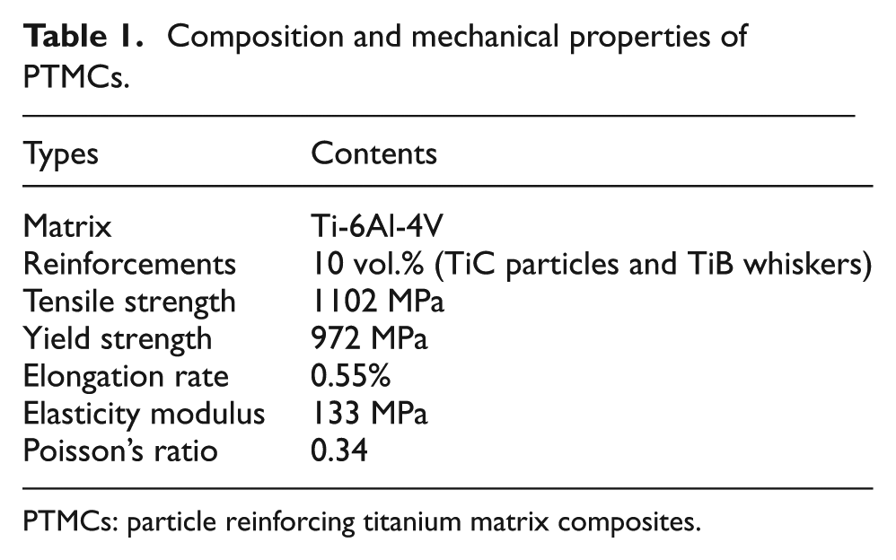
PTMCs: particle reinforcing titanium matrix composites.
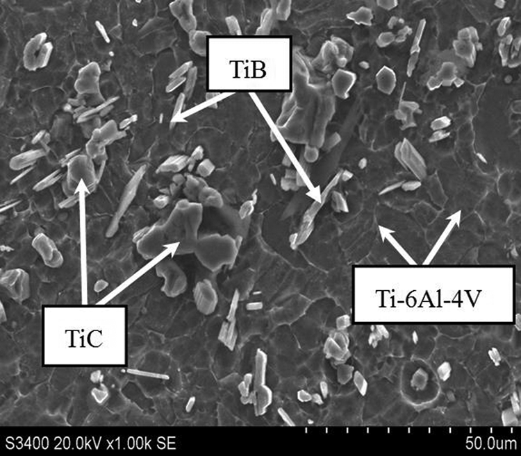
SEM microstructure of (TiCp + TiBw)/Ti-6Al-4V composites (polished and etched).
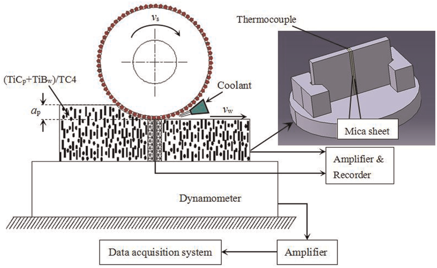
Illustration of the experimental setup.
The vitrified CBN wheel and electroplated CBN wheel, which have an identical wheel diameter and grain sizes, are shown in Figure 3. Prior to each grinding test, the vitrified CBN wheel was freshly dressed with a single-point diamond dresser at a grinding speed of 20 m/s, workpiece speed of 3 m/min and depth of cut of 0.005 mm. The cumulative dressing depth was 0.050 mm. Grinding experiments were performed on the grinding machine model BLOHM PROFIMAT MT-408. The maximum rotational speed was 8000 r/min and the output power was 45 kW. The conditions for the grinding tests are presented in Table 2. Table 3 displays the specification of the two CBN wheels.

CBN wheels used in high-speed grinding PTMCs: (a) vitrified CBN wheel and (b) electroplated CBN wheel.
Conditions for the high-speed grinding process.
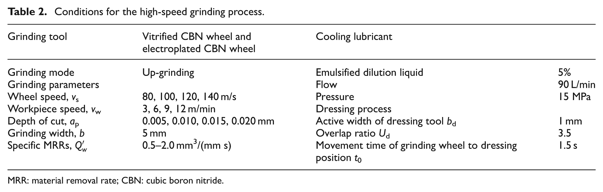
MRR: material removal rate; CBN: cubic boron nitride.
Specification of CBN wheels.
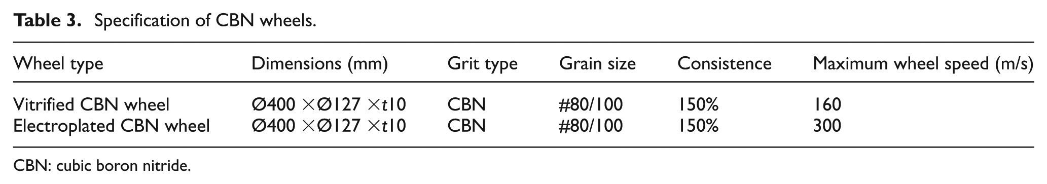
CBN: cubic boron nitride.
The grinding forces were measured with a piezoelectric dynamometer (Kistler 9272), coupled to charge amplifiers and a PC running Dynamometer software. A constantan wire–workpiece semi-natural thermocouple was applied to measure grinding temperature. The surface roughness was measured with a Mahr M1 surface roughness tester. The morphology of the ground surface and defects was characterized using KH-7700 optical microscope and scanning electron microscopy (SEM; Quanta 200) coupled with an energy-dispersive spectrometer (EDS).
Experimental results and discussion
Comparison of grinding forces in high-speed grinding
The grinding forces, that is, normal force and tangential force, play a significant role in quantitatively analyzing the grinding performance. 25 Comparative analysis on the grinding forces of the vitrified CBN wheel and electroplated CBN wheel was carried out under the identical conditions in the current investigation. Here, the wheel speed was between 80 and 140 m/s, the depth of cut ranged from 0.005 to 0.020 mm, and the workpiece speed was between 3 and 12 m/min.
Figure 4 displays the measured grinding forces as functions of the workpiece speed, the depth of cut, the wheel speed, and the specific material removal rates. As can be seen from Figure 4(a), the increase in workpiece speed leads to an increase in both the normal and tangential grinding forces. When the depth of cut is 0.010 mm and the workpiece speed is fixed at 3 m/min, the normal force is 18.37 N with vitrified CBN wheel and 19.26 N with electroplated CBN one. The tangential force is 5.11 N with vitrified CBN wheel and 4.37 N with electroplated CBN one. However, when the workpiece speed is increased from 3 to 12 m/min, the normal force is increased remarkably by 120% to 39.90 N with vitrified wheel and by 100% to 38.78 N with electroplated CBN one. In addition, the tangential force is raised by 80% to 9.34 N and by 100% to 8.63 N.
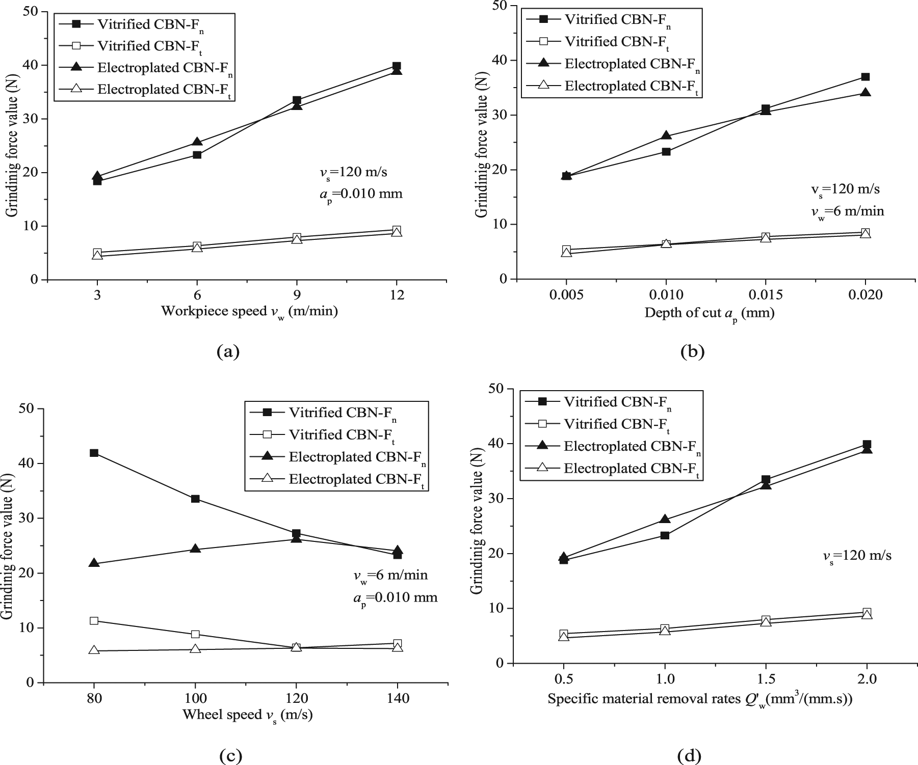
Influence of machining parameters on grinding force: (a) workpiece speed, (b) depth of cut, (c) wheel speed, and (d) specific material removal rates.
When the depth of cut is increased from 0.005 to 0.020 mm, the normal force is raised rapidly by 100% from 18.79 to 36.98 N and the tangential force is also increased by 60% from 5.42 to 8.48 N using vitrified CBN wheel (Figure 4(b)). For the electroplated CBN wheel, the recorded normal force is raised rapidly by 80% from 18.76 to 33.99 N, and the tangential force is also increased approximately by 70% from 4.63 to 8.07 N.
A higher wheel speed results in a smaller grinding force with vitrified CBN wheel (Figure 4(c)). When the wheel speed is increased from 80 to 140 m/s, the normal force is decreased by 80% from 41.92 to 23.30 N and the tangential force is also decreased by 110% from 11.28 to 5.38 N. At the same time, for the electroplated wheel, the normal force is merely increased by 10% from 21.72 to 24.07 N and the tangential force is always kept in a rather narrow scale, that is, 5.79–6.23 N.
Figure 4(d) shows the variation of the grinding forces with respect to the specific material removal rate
Comparison of grinding temperature in high-speed grinding
In the grinding process, a large amount of energy is consumed at the interface between the wheel and the workpiece due to the frictional heat and localized plastic deformation. 26 The energy consumed leads to a significant increase in the temperature associated with the onset of thermal deformation and thermal damage of the ground material, that is, softening, burning, micro-cracks, and reduced fatigue strength. 27 Figure 5 displays the grinding temperature versus the machining parameters. The increasing tendency of the grinding temperature is plotted against the workpiece speed and the depth of cut, which is correlated with the specific grinding energy in the current investigation. Particularly, it is found that the grinding temperature values with the vitrified CBN wheel are always higher compared to those with the electroplated CBN wheel. When the workpiece speed is 3 m/min and the depth of cut is 0.01 mm, the experimental grinding temperature is 805 °C with the vitrified CBN wheel.
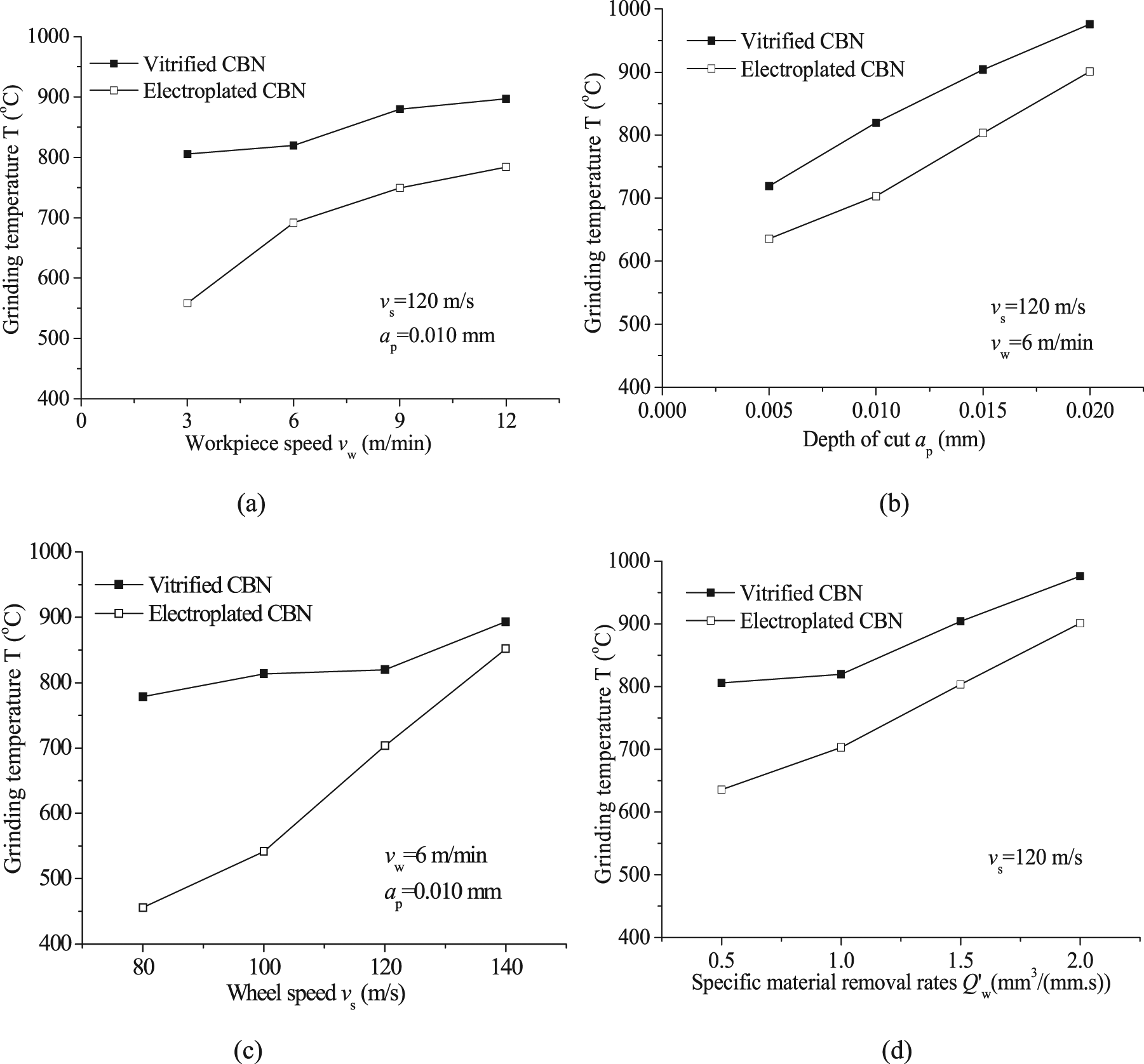
Influence of machining parameters on grinding temperature: (a) workpiece speed, (b) depth of cut, (c) wheel speed, and (d) specific material removal rates.
As can be seen from Figure 5(a), when the workpiece speed is increased from 3 to 12 m/min, the grinding temperature is increased weakly by 12% to 900 °C for the vitrified CBN wheel. Meanwhile, the recorded grinding temperature for the electroplated CBN wheel is increased remarkably from 560 °C to 780 °C, which is increased approximately by 40% with the identical grinding parameters. Furthermore, when the depth of cut is 0.005 mm and the workpiece speed is fixed at 6 m/min, the grinding temperature is 720 °C for vitrified CBN wheel and 635 °C for electroplated CBN wheels.
In addition, it is observed that when the depth of cut is increased to 0.020 mm, the temperature is increased approximately by 36% to 980 °C for the vitrified CBN wheel and by 42% to 900 °C for the electroplated CBN wheel, as shown in Figure 5(b). Figure 5(c) demonstrates the measured grinding temperature as a function of wheel speed. Here, the workpiece speed is 6 m/min and the depth of cut is 0.010 mm, while the wheel speed is increased from 80 to 140 m/s. The grinding temperature is merely increased by 14% from 780 °C to 890 °C for the vitrified wheel, while the recorded temperature is raised rapidly by 90% from 450 °C to 850 °C for the electroplated wheel. As can be seen from Figure 5(d), when the specific material removal rate is 0.5 mm3/(mmċs), the grinding temperature is 805 °C for the vitrified CBN wheel and 635 °C for the electroplated CBN wheel. Meanwhile, it is found that when the specific material removal rate is increased to 2 mm3/(mmċs), the temperature is increased approximately by 22% to 980 °C for the vitrified wheel and by 42% to 900 °C for the electroplated wheel. Based on the grinding temperature shown in Figure 5, it is known that the electroplated CBN wheel is more suitable for grinding PTMC materials compared to the vitrified CBN counterpart.
Comparison of specific grinding energy in high-speed grinding
The specific grinding energy es, which is the ratio of the grinding power to the material removal rate, is one of the most important indices for characterizing the grinding process.28,29 The specific grinding energy obtained with the grinding parameters and the recorded tangential force Ft is represented by 30

where b is the width of ground zone, that is, 5 mm in this investigation.
In this investigation, the random distribution of the abrasive grains of the vitrified CBN wheel and electroplated CBN wheel is considered and the maximum undeformed chip thickness (ag, max in short) is written as 31
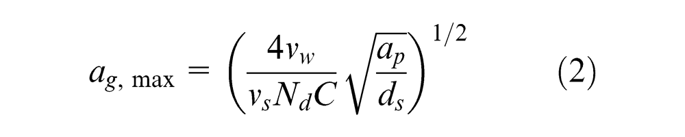
where Nd is the active cutting point density, which is 7.90 mm−2 for the vitrified CBN wheel and 11.68 mm−2 for the electroplated CBN wheel. C is a constant correlated with the angle of the grain tip, which can be taken to be 6.928. 32
Based on the tangential grinding force and the grinding parameters presented in Figure 4, the specific grinding energy of PTMCs is obtained and plotted against the undeformed chip thickness for the vitrified CBN and electroplated CBN wheels, as displayed in Figure 6. The specific grinding energy in this investigation using the least-squares curve-fitting technique to the experimental data is written as follows.
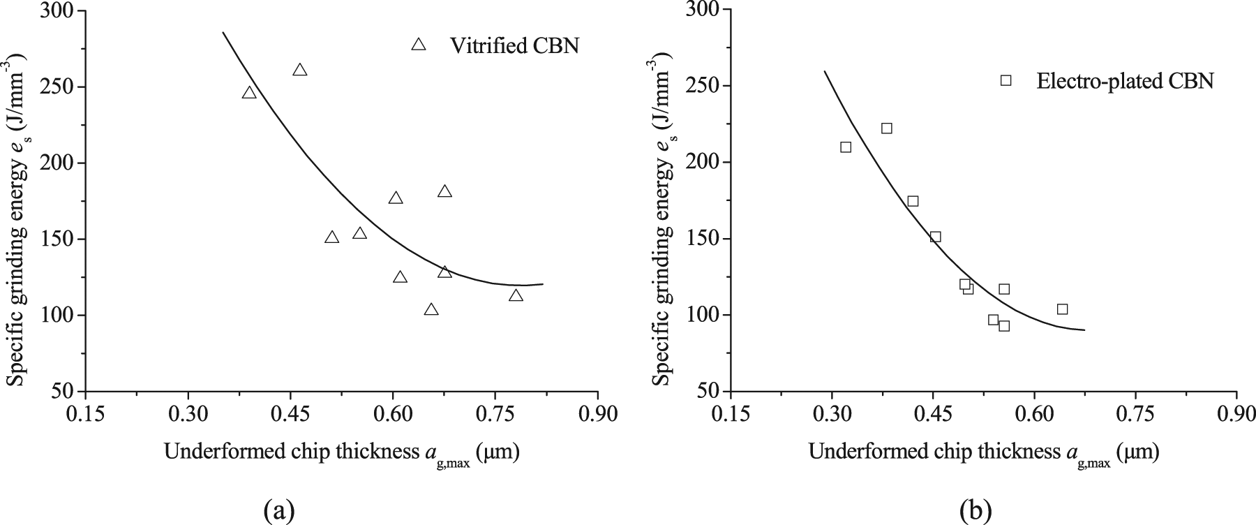
Effect of undeformed chip thickness on specific grinding energy: (a) vitrified CBN wheel and (b) electroplated CBN wheel.
For the vitrified CBN wheel

For the electroplated CBN wheel

As can be seen from Figure 6, it is evident that the specific grinding energy is gradually decreased with the increase in the undeformed chip thickness. This phenomenon can be explained by the fact that the high specific grinding energy of PTMCs is mainly attributed to high plowing and sliding energies with a small undeformed chip thickness. It is expended in grinding in excess of energy of chip formation by cutting. The percentage contributions from sliding and plowing diminish with the increase in the undeformed chip thickness, and hence, the specific grinding energy decreases with the undeformed chip thickness as well.
In general, less specific grinding energy is required for the electroplated CBN wheel to machine PTMCs. For example, when the workpiece speed is 3 m/min, the depth of cut is 0.010 mm, and the wheel speed is 120 m/s, the specific grinding energy, 210 J/mm3, with the electroplated CBN wheel is remarkably lower than that, 245 J/mm3, with the vitrified CBN wheel. That is to say, the electroplated CBN wheel is more suitable for grinding PTMCs compared to the vitrified CBN wheel according to the specific grinding energy.
Comparison of ground surface in high-speed grinding
The surface roughness is an important quantitative indicator to assess the ground surface quality.33,34 In this investigation, surface roughness values of the ground specimens were measured five times for each set of grinding parameters. When the electroplated CBN wheel was used to grind PTMCs, the surface roughness Ra was varied in the range of 1.2–1.4 μm. Here, the wheel speed range is between 80 and 140 m/s, the workpiece speed is 6 m/min, and the depth of cut is 0.010 mm. A slightly larger value of the ground surface roughness Ra, that is, 1.5–1.7 μm, is obtained for the vitrified CBN wheel under identical conditions.
Figure 7 shows the typical two-dimensional (2D) surface morphology and three-dimensional (3D) contour curved surface of the specimens ground with the vitrified CBN wheel and the electroplated CBN counterpart. Here, the wheel speed is 120 m/s, the workpiece speed is 6 m/min, and the depth of cut is 0.010 mm. As can be seen from Figure 7, the grooves of the ground profile curve are deeper with the vitrified wheel compared to those with the electroplated one, which corresponds to the larger value of the ground surface roughness using the vitrified CBN wheel. Therefore, better ground surface is obtained when the electroplated CBN wheel is applied. The defects of the surface ground with the electroplated CBN wheel are analyzed in detail in the following investigation.
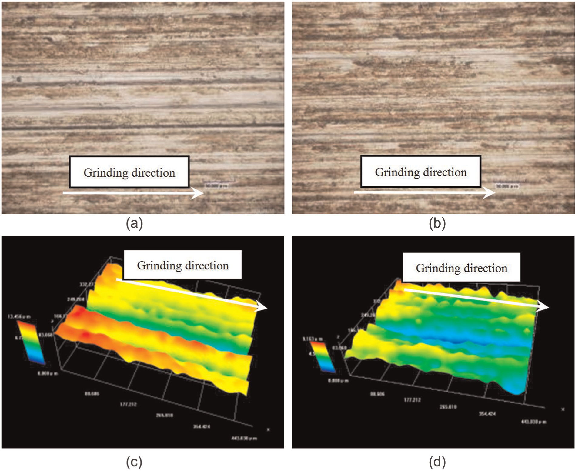
2D image and 3D profiles of the ground surface: (a) 2D image with vitrified CBN wheel, (b) 2D image with electroplated CBN wheel, (c) 3D morphology of grooves scratch with vitrified CBN wheel, and (d) 3D morphology of grooves scratch with electroplated CBN wheel.
Figures 8 and 9 show the typical ground surface morphology with the electroplated CBN wheel. The grinding direction is illustrated in these images. It is observed from Figure 8(a) that holes and grooves emerge due to the decohesion between the reinforcements and the Ti-6Al-4V matrix. The images of the amplification of A and B are shown in Figure 8(b) and (c), respectively. The 3D morphology of the grooves is shown in Figure 8(d), which indicates the existence of the long grooves parallel to the grinding direction on the machined surface (Figure 8(b)). 35 The 3D morphology of holes is presented in Figure 8(e), which indicates the hole corresponding to Figure 8(c). Figure 8(f) shows the schematic image of the holes on the ground PTMCs surface. As can be seen from Figure 8(b), the grooves are formed due to the reinforcements being pulled out from the matrix and becoming dragged along the surface for a distance, which result in the formation of scratches of various lengths. Meanwhile, the tested point of the particle in Figure 8(b) was analyzed using the energy-dispersive spectrometry (EDS). The EDS result of the reinforcing particle is displayed in Figure 8(g), according to which the reinforcing particles containing C and Ti are identified to a certain extent. Meanwhile, the alloy elements of the matrix, that is, Ti, Al, and V, always exist around the TiC particle. In Figure 8(c), some holes emerged on the ground surface region, which is because that the pullout behavior of the reinforcements was partially or totally detached from the machined surface and left behind cavities of various sizes and shapes.12,36
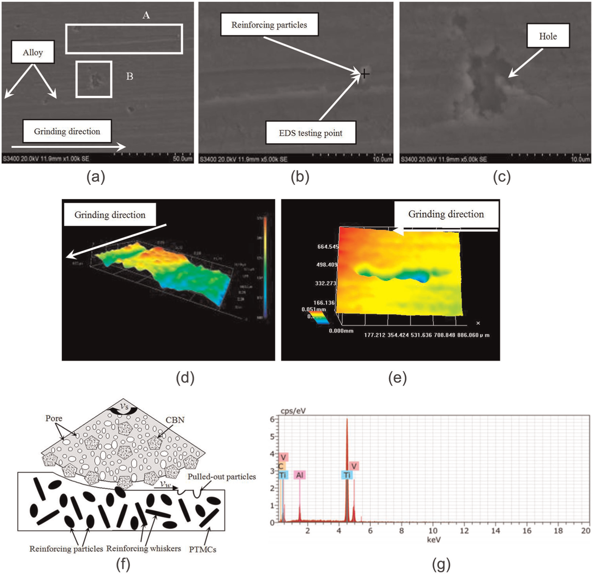
Typical ground surface morphology and EDS microanalysis: (a) machined surface, (b) local amplification of A, (c) local amplification of B, (d) 3D morphology of groove scratch, (e) 3D morphology of pulled-out particles, (f) schematic, and (g) EDS result of the testing point.
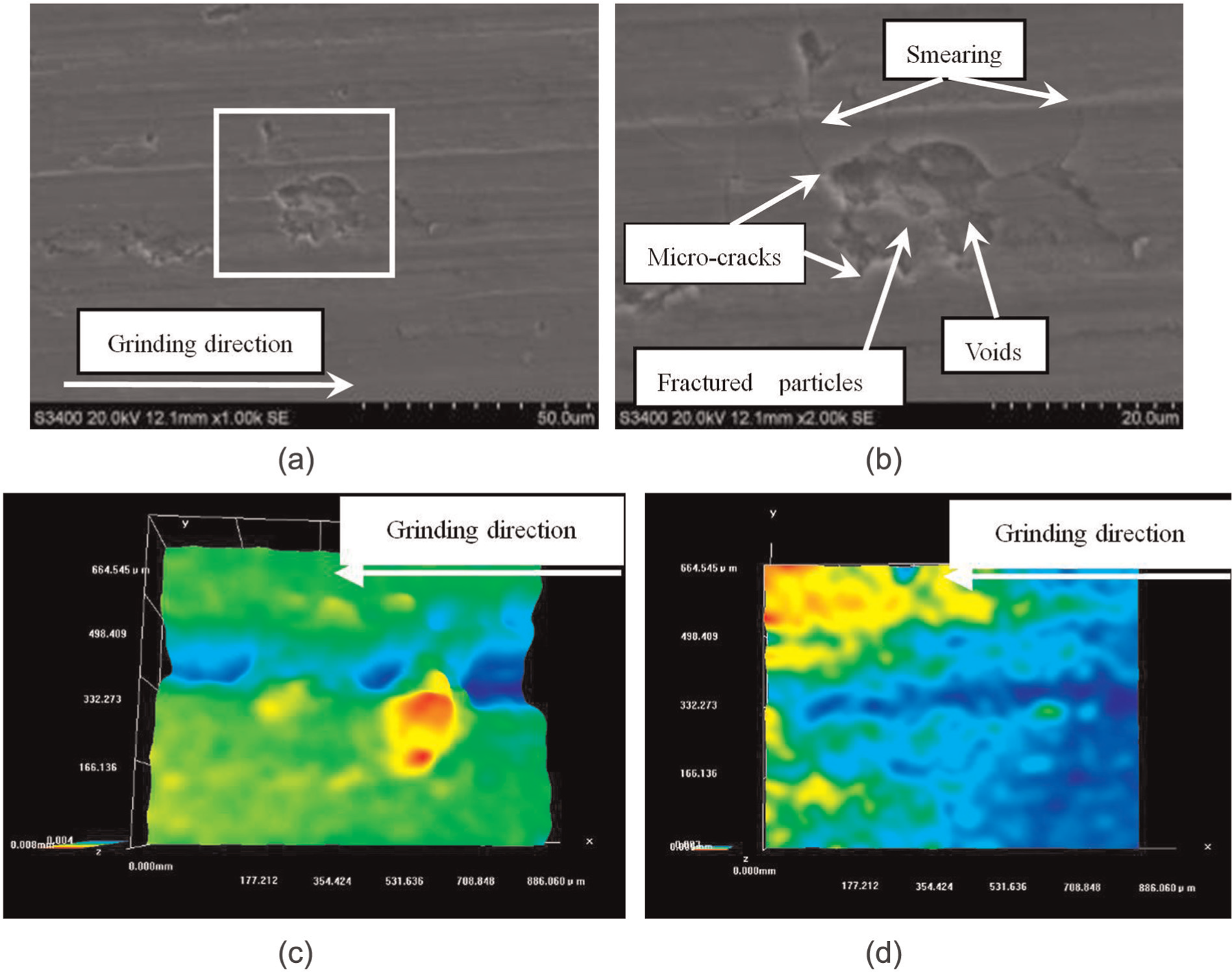
Voids and smearing on the ground surface morphology: (a) machined surface, (b) regional morphology, (c) 3D morphology of the voids, and (d) 3D morphology of the smearing.
The magnified image of the regional morphology of the machined surface in Figure 9(a) is shown in Figure 9(b). As can be seen from Figure 9(b), the voids are generated around the reinforcing particles. The 3D morphology of the voids is shown in Figure 9(c), which indicates the voids’ profile. The phenomenon can be explained by the fact that some reinforcing particles or whiskers were partially detached from the machined surface and the dislocation pile-ups near the ground surface region, which is owing to the fact that the fractured reinforcing particles were pressed into the machined surface. 33 At the same time, the smearing on the machined surface is observed as shown in Figure 9(b). The reason is that the machined surface is covered with the molten Ti-6Al-4V alloy matrix material due to the redistribution and cooling on the ground surface under the high grinding temperature and the residual chips excluded incompletely. The 3D morphology of the smearing is shown in Figure 9(d). It is found that the micro-cracks were initiated around the voids and extended to the Ti-6Al-4V alloy matrix, which perhaps decrease the fatigue life of the material.
Chips in high-speed grinding
In order to analyze the surface generation mechanism from the viewpoint of the material removal process, the grinding chips of PTMCs obtained using the electroplated CBN wheel were collected and observed. Here, the wheel speed was 120 m/s, the workpiece speed was 6 m/min, and the depth of cut was 0.010 mm. The grinding parameters were selected based on the comprehensive consideration of the specific material removal rate and the appropriate grinding temperature to avoid the burn of the machined surface. Figure 10(a) shows the morphology of the typical segmental chip, which can be explained based on the grain–workpiece interaction. 37 During grinding, the side swelling gradually forms along both the sides of a groove due to the extrusion action between the abrasive grains and the workpiece material, which results in the creation of a stagnation zone and subsequent upsetting of the workpiece material. The side swelling becomes larger with an increase in the deformation of the main deformation zone. When the shear strain rate of the main deformation zone is increased, the shear zone becomes smaller. A short segmental chip is generated. Furthermore, the longer segmental chips are produced with the continuing slippage of the short segmental chip in the grinding process. 38 Meanwhile, the reinforcing particles or whiskers partially detached from the machined surface probably flow with the grinding chips. As can be seen from Figure 10(b), the reinforcing particles emerge on the surface of the grinding chips.
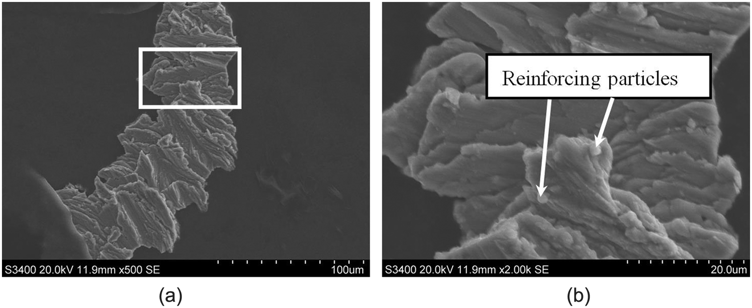
Morphology of the PTMC chips obtained in high-speed grinding: (a) grinding chip and (b) regional morphology.
Conclusion
High-speed grinding experiments of (TiCp + TiBw)/Ti-6Al-4V composites (PTMCs) were carried out with the vitrified CBN wheel and electroplated CBN wheel. The cutting behavior, that is, the grinding force, grinding temperature, specific grinding energy, and ground surface morphology, and grinding chips are investigated. Based on the results obtained from the high-speed grinding experiments, the following conclusions could be drawn:
Compared to the workpiece speed and the depth of cut, the wheel speed has more influence on the grinding forces for both the vitrified CBN wheel and electroplated counterpart. The grinding forces obtained with the vitrified wheel are generally larger than those obtained with the electroplated wheel regardless of the wheel speed when the workpiece speed and depth of cut are fixed.
The grinding temperature and specific grinding energy obtained with the vitrified CBN wheel are always higher than those with the electroplated CBN wheel, which indicated that the electroplated CBN wheel is more suitable for high-speed grinding of PTMCs.
The reinforcements of PTMCs are removed in the form of pullout, fracture or crushing, micro-cracks, voids, and smearing, which results from the plowing and shearing behavior during high-speed grinding. The segmental chips containing the reinforcements are formed during grinding PTMCs.
Footnotes
Declaration of Conflicting Interests
The author(s) declared no potential conflicts of interest with respect to the research, authorship, and/or publication of this article.
Funding
The author(s) disclosed receipt of the following financial support for the research, authorship, and/or publication of this article: This study was co-supported by the National Natural Science Foundation of China (No. 51235004 and No. 51375235), the Fundamental Research Funds for the Central Universities (No. NE2014103), Qinglan Project, and 333 Project of Jiangsu Province.