
Abstract
Geometrical error in abrasive waterjet turned parts is an important challenge toward the commercialization of abrasive waterjet turning process. A systematic study has not been done yet to investigate the effects of process parameters on geometrical error in abrasive waterjet offset-mode turning. In this article, a comprehensive study has been performed to investigate the influence of several machining parameters on the geometrical error (part diameter percent error) in turning AA2011-T4 aluminum alloy round bars. Water pressure, cutting head traverse speed, workpiece rotational speed, abrasive mass flow rate and depth of cut were considered as the main machining parameters in a five-level statistical experimental design. Based on central composite rotatable design, a total of 52 experiments were carried out. The main effects of the parameters and interactions among them were analyzed based on the analysis of variance technique, and the response contours for the part geometrical error were obtained using a quadratic regression model (i.e. response surface methodology). The model predictions were found to be in good agreement with experimental data. Furthermore, among the significant parameters, water pressure, depth of cut and traverse speed are the most influential parameters, with percent contribution of almost 25% each. Abrasive mass flow rate is the least influential parameter with a percent contribution of 4%.
Introduction
Abrasive waterjet turning (AWJT) is an innovative non-traditional machining technique that enables using advantages of waterjet in producing axisymmetric parts.1–5 In the AWJT process, the workpiece revolves while the cutting head axially moves with a definite depth of cut (DOC) to produce the required geometry (Figure 1). AWJT has superior benefits in comparison with a conventional turning. Material removal takes place by means of a flexible cutting tool (AWJ), so AWJT is less sensitive to the workpiece shape. It allows to machine at high depths of cut in one pass and offers fairly higher material removal rates (MRRs), especially for hard-to-machine materials.5,6 The process involves low cutting forces, so it is quite independent of the workpiece length-to-diameter ratio and therefore enables to turn long parts with small diameters. 7 Since abrasives have the capability to erode almost any materials, this process is ideally suitable for materials with low machinability such as ceramics, composites, glass and titanium alloys.6,8,9 However, this process involves some challenges that limit its rapid growth and use in industries. Experimental investigations of this technique by pioneers, Ansari 2 and Hashish, 1 show that AWJT is a near-net shape machining process. It was reported that the final diameter of the turned part is usually more than the desired diameter because of the jet deflection and its instability. 10 However, from a visualization study, Ansari et al. 11 pointed out how the AWJ does not undergo any significant radial deflection in the region where material removal takes place. Axinte et al. 5 utilized AWJT as an efficient method to profile and dress grinding wheels and proved its technological and economical capability. They could turn parts up to ±0.1 mm accuracy. Studies on precision turning with AWJ showed that the accuracy of turned parts is affected by the jet trail-back and deflection.10,12 Machining at high traverse speeds and depths of cut causes jet instability, which results in rougher surfaces, striation marks, poorer roundness and inconsistency in achieving the desired diameter.
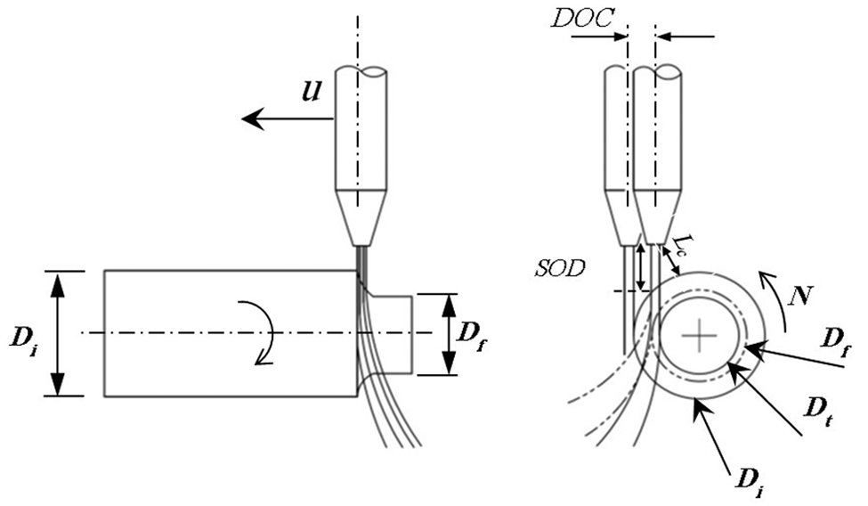
AWJ offset-mode turning process schematic.
Depending on the position of the nozzle/jet relative to the workpiece, Li et al. 13 classified AWJT as “radial-mode” or “offset-mode.” They evidenced the advantages of radial-mode turning over the offset-mode turning, including more jet energy utilization, higher surface speeds, capability of nozzle tilt angle variations and smaller nozzle stand-off distances. These factors enable the process to provide higher MRRs. However, controlling the DOC seems to be still an important challenge for radial-mode turning.
Some mathematical models capable of estimating the workpiece diameter continuous change in AWJT were also presented.2,7,14–16 An analytical model suggested by Ansari 2 relates the volume swept by the combined specimen rotation and cutting head traverse in the time unit (defined as the volume sweep rate (VSR)) to the MRR. This model could predict the workpiece final diameter for various sets of AWJT parameters. Despite the continuous variation in impact angle during the workpiece diameter reduction, Hashish’s analytical model does not consider impact angle modifications. An erosion-based approach considering the varying local impact angle was presented by Manu and Babu 7 to predict the workpiece final diameter. However, their model does not accurately predict the final diameter at various traverse speeds. Moreover, when the impact angle tends to 0, their model overestimates the removed material volume. By applying Hashish’s erosion model, Zohourkari and Zohoor15,17 presented a model with better estimation in terms of final diameter prediction. Hlavac and Palicka 16 presented a very comprehensive model, even if all the mentioned models do not consider the reduction in jet energy utilization at depths of cut lower than the jet diameter, the exact material flow stress and the focusing nozzle wear. Analytical models are still in their early stages and must be developed to become practical. Thus, statistical models that are capable of including the effects of controllable and uncontrollable parameters can be useful to model the AWJT process.
To develop the applicability of AWJT and to improve its accuracy, it is important to study the effects of operational parameters on the turned parts’ geometrical error and look for strategies to reduce it. Up to now, the lack of a systematic experimental study on AWJT able to show the effect of parameters on geometrical error is sensible; therefore, the effects of several machining parameters on the part geometrical error in AWJ offset-mode turning of AA2011-T4 are investigated in this article. Five major machining parameters such as water pressure, cutting head traverse speed, workpiece rotational speed, abrasive mass flow rate and DOC were considered in a five-level statistical experimental design. Based on central composite rotatable design (CCRD), a total of 52 experiments were carried out. The main effects of parameters and interactions among them were analyzed based on the analysis of variance (ANOVA) technique by Minitab 16® software. The response contours for the geometrical error, defined as the part diameter percent error, were obtained using a quadratic regression. All parameters investigated in this research can be adjusted to the desired levels, and their continual change is possible. It must be noted that there are other effective parameters such as orifice and focusing tube diameter, focusing tube length, abrasive material, size and shape, but this study is devoted to act on the most controllable parameters in a standard waterjet machining center, keeping other parameters at a representative and significant level. This work aims to obtain a valuable understanding of the effects of parameters in the AWJ offset-mode turning process and presents a statistical model suitable to improve its accuracy.
AWJT strategy
Based on the relative position of jet and workpiece, AWJT can be classified as radial-mode or offset-mode turning. Advantages of offset-mode turning compared to radial-mode turning are the ability of controlling the DOC 13 and better surface quality.1,4,18 Hence, AWJ offset-mode turning has been chosen for this study since it seems to be more suitable to meet industrial requirements. The schematic of the AWJ offset-mode turning is shown in Figure 1. In this process, the AWJ is adjusted in a desired position defining the nominal DOC and minimum distance between the focusing tube tip and the workpiece surface (Lc). The workpiece rotates at the rotational speed N, while the jet moves along the workpiece rotation axis at the traverse speed u and erodes the workpiece surface in one pass to the final diameter (Df). The direction of rotation plays an important role in the surface quality of turned parts. It was reported that the surface quality is better when the sample is turned so that the relative velocity between the jet and the part is lesser.1,18 When the sample is turned in the counterclockwise (CCW) direction (Figure 1), better surface quality would be expected. Because of low cutting forces and no cutting tool wear, since the AWJ is the tool, it is possible to turn parts at high depths of cut in one pass. 6 Ideally, at the end of the part exposure to the jet, the jet becomes tangent to the surface of the workpiece. But, in practice, the final part diameter is more than the target diameter (Dt), which introduces a geometrical error.
Experiments
The AWJT experimental apparatus was prepared by applying an AWJ machine (Tecnocut 5-axis handling system with a Flow 9XV-S 380 MPa pump) that is equipped with a custom-built lathe with maximum rotational speed equal to 1000 r/min (Figure 2).
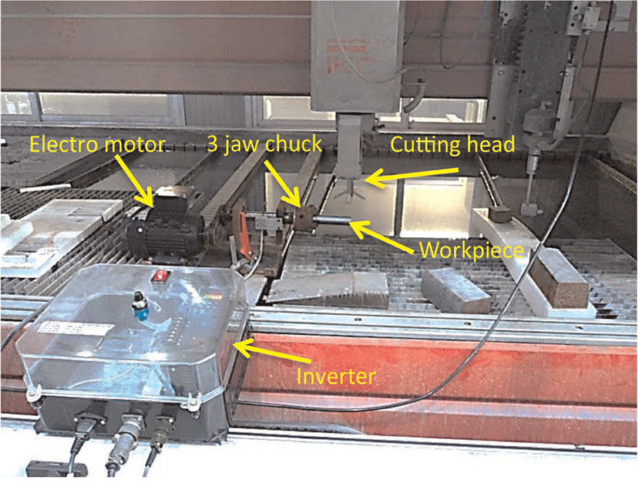
The experimental setup for abrasive waterjet turning.
AA2011-T4 round bars of 30 mm diameter were selected for this study. The bars were cut to 10 cm length parts and carefully cleaned with ethanol alcohol. The material composition of AA2011-T4 is given in Table 1.
AA2011-T4 composition.
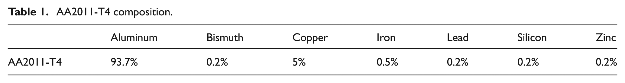
Based on previous researches by Hlavac and colleagues,19–22 the shape and size of abrasives are changed due to their fragmentation while mixing and accelerating in the AWJ cutting head. This phenomenon depends on several parameters such as pressure, abrasive mass flow rate, orifice size, mixing chamber inner shape and focusing tube length and internal diameter. Since the final size and shape of abrasives involved with the machining process are not independent of other selected process parameters, their effects were not investigated in this study separately. Mesh #80 GMA Australian Garnet was used for all the experiments (Figure 3). A standard 0.3-mm-diameter orifice and a standard 1.02-mm-diameter focusing tube were used for all the tests.
Image of the mesh #80 GMA Australian Garnet used for the experiments taken by Alicona InfiniteFocus®.
DOC adjustment
To obtain the required workpiece geometry, it is important to accurately adjust the DOC. The reference system applied to set the DOC at each experimental run has been defined by carrying out an accurate workpiece alignment procedure, allowing the jet traverse line to be parallel to the workpiece axis and the jet to be tangent to the workpiece circumference. Low water pressure has been used during such a procedure in order to obtain a very thin and coherent jet. After the DOC adjustment, the distance between the focusing tube tip and the workpiece surface (Lc) was set to 1 mm to avoid any collisions.
Experimental design
The ranges of the selected factors, that is, water pressure (P), cutting head traverse speed (u), workpiece rotational speed (N), abrasive mass flow rate (
The distance of the axial points from the center point is determined by the α value.
23
For a CCRD,
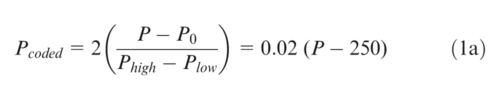
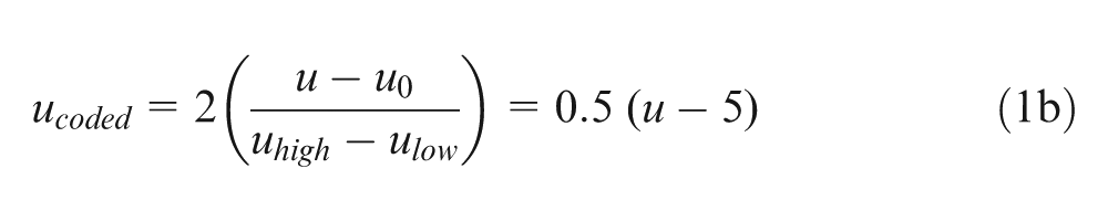
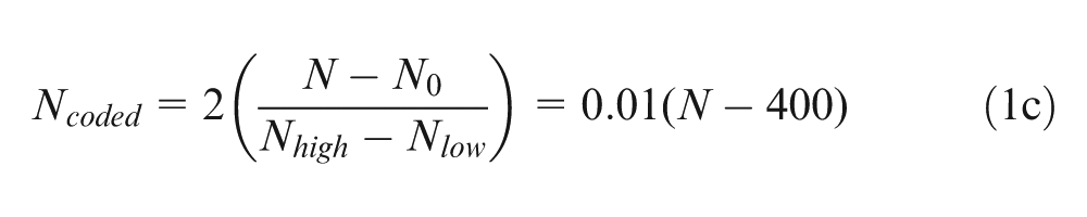
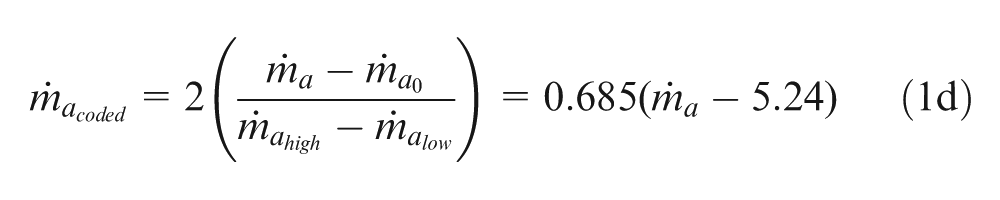
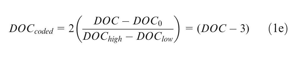
The experimental factors are given in Table 2, where their coded and actual values are reported. Coding factor is an important step in response surface analysis which allows a direct comparison of the factors’ weight on the process response.23,24 Thus, higher and lower levels of the corner points were coded to +1 and −1, respectively; the center points were coded to 0 and higher and lower levels of axial points were coded to +α and −α correspondingly. The linear relationships between the coded and the actual factor values are given in equations 1(a)–(e)
Variable factors of the AWJT experimental campaign.
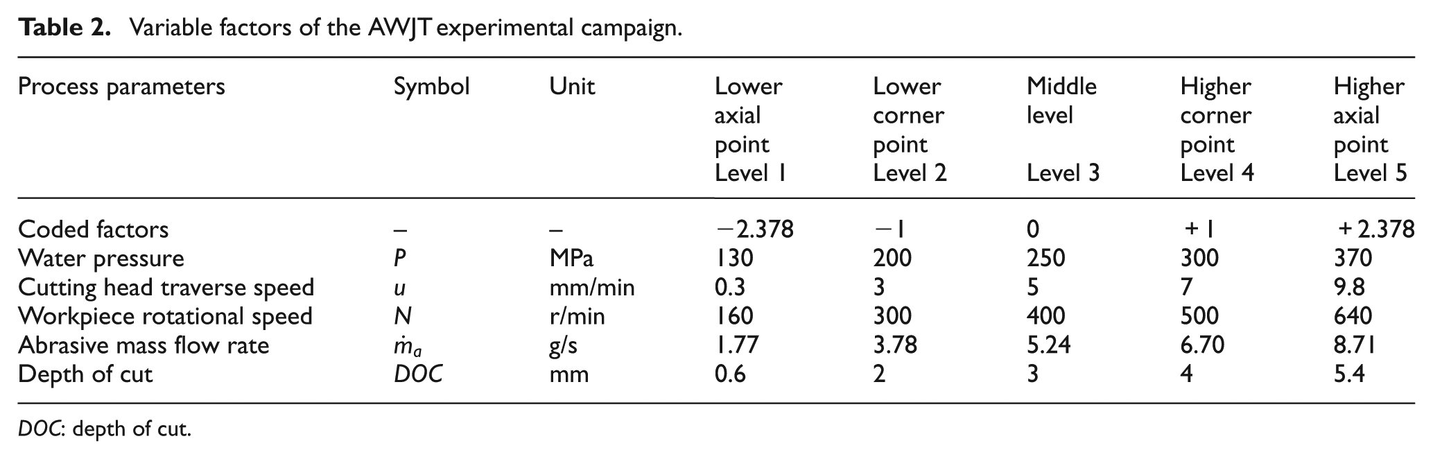
DOC: depth of cut.
Subscripts high and low represent the higher and lower levels of corner points, respectively, and subscript “0” indicates the center point.
The initial and final diameters, Di and Df, respectively, were measured by means of a Zeiss Prismo 5 HTG VAST coordinate measuring machine (Figure 4), and the geometrical error GE, defined as the part diameter percent error, was calculated according to equation (2)
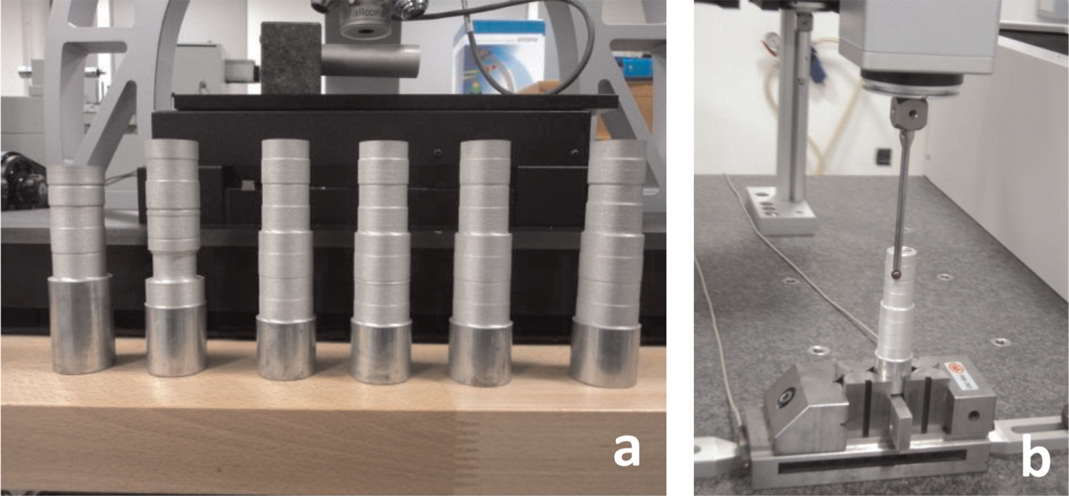
(a) Abrasive waterjet turned parts and (b) measurement of the final diameter of turned parts by the Zeiss Prismo 5 HTG VAST CMM.
Response surface methodology
Response surface methodology (RSM) is a statistical approach to find a mathematical form of the relationship between the process responses and the process parameters using statistical and mathematical techniques.23,25–27 The mathematical equation stating the relationship between the AWJT process parameters and the geometrical error response can be expressed as
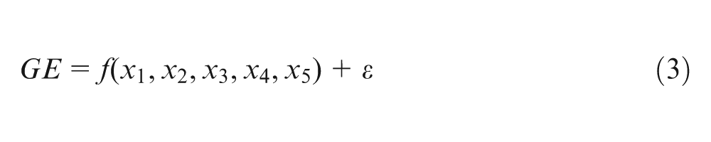
where f is the response function;
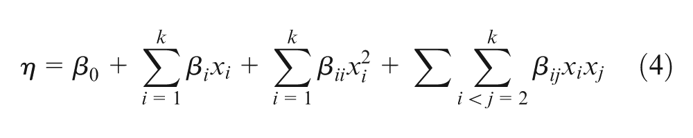
where
Results and discussions
Statistical modeling of part geometrical error
AWJ turned parts obtained from planned experiment (i.e. 32 corner points (nF = 32), 10 center points (nc = 10) and 10 axial points (na = 10)) are shown in Figure 4.
According to the model defined by equation (2), a statistical analysis was accomplished considering the part geometrical error as process response. The ANOVA results for the geometrical error are shown in Table 3. As shown in this table, it is possible to conclude that the second-order regression model is significant since its respective p value is sufficiently less than 0.05. Moreover, the null hypothesis of no lack of fit cannot be rejected (p value higher than 0.05), which shows that no other predictors are required.
ANOVA table for the regression model of geometrical error.
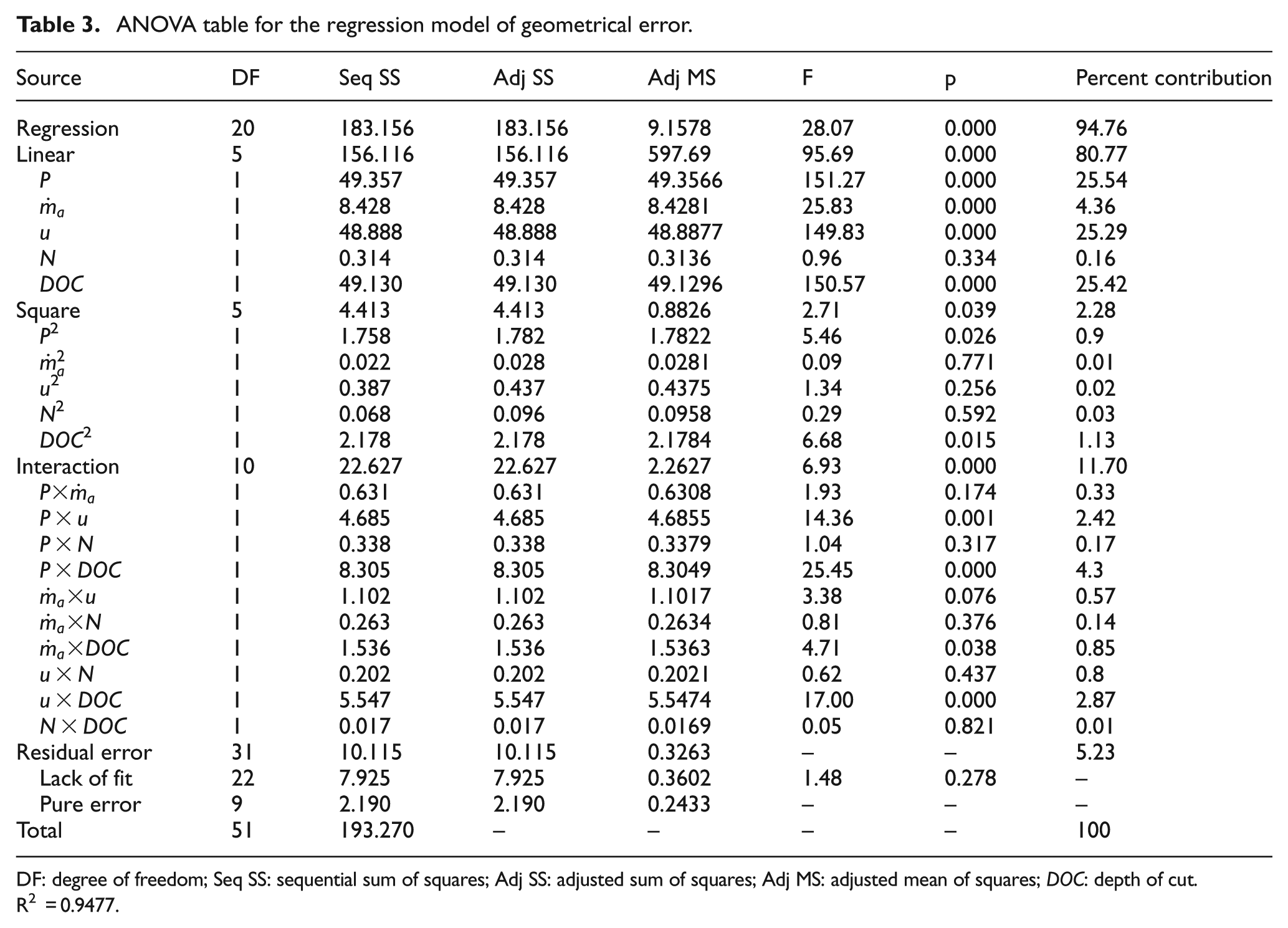
DF: degree of freedom; Seq SS: sequential sum of squares; Adj SS: adjusted sum of squares; Adj MS: adjusted mean of squares; DOC: depth of cut.
R2 = 0.9477.
It has been found that among the input process parameters, water pressure, cutting head traverse speed, abrasive mass flow rate and DOC are significant and workpiece rotational speed is insignificant. In addition, second-order terms of water pressure (P2) and DOC (DOC2) and interaction between water pressure and traverse speed (P × u), water pressure and DOC (P × DOC), abrasive mass flow rate and DOC (
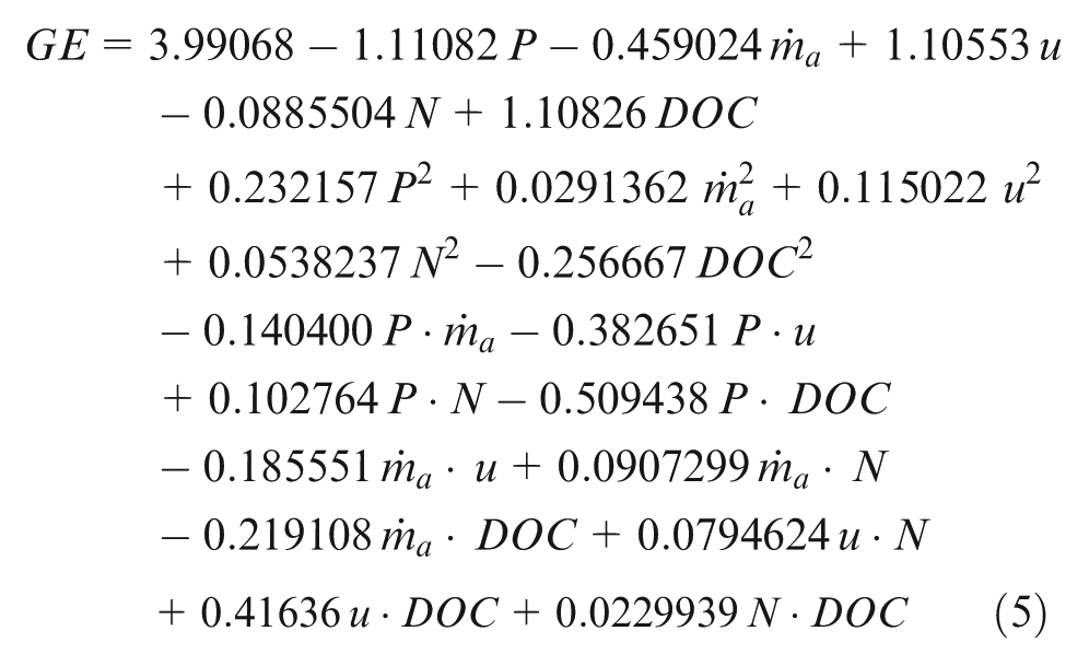
The experimental data (observed responses) and the predicted values (fitted responses) are shown in Figure 5. As seen in the figure, the obtained model describes the experimental data well. Upon this, the final model for geometrical error is given in equation (5)
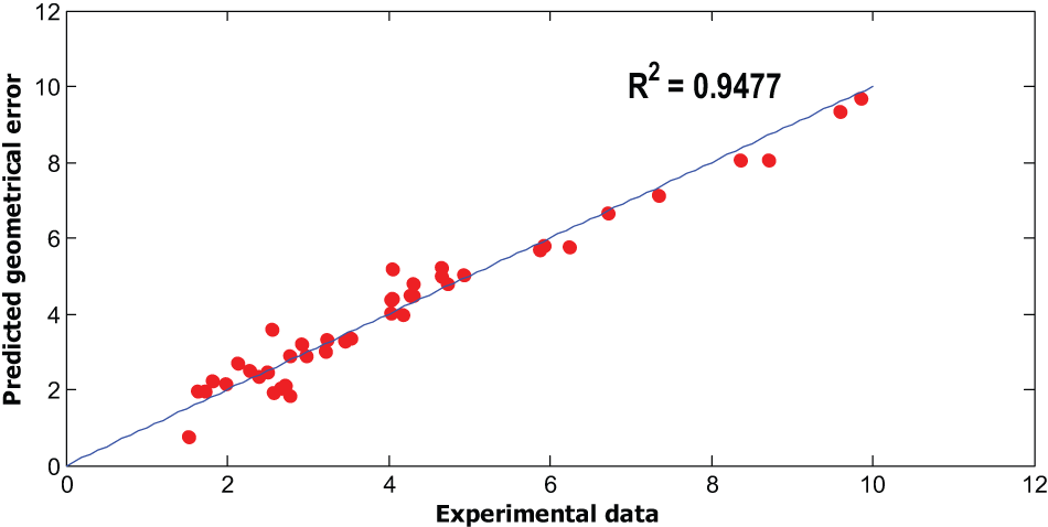
Predicted values versus experimental data.
To evaluate the fitting adequacy of the model, the coefficient of determination R2 has been calculated. The R2 value indicates that 94.77% of the total deviations in the process response can be explained by the model. While the R2 approaches unity, the model fits the experimental data accurately. 23
Effects of the process parameters on geometrical error
Percent contributions of the model effects have been calculated from their sequential sum of squares (Seq SS) as shown in Table 3 and are graphically shown in Figure 6. It illustrates that among process parameters, water pressure, cutting head traverse speed and DOC are the most influential parameters in controlling the part geometrical error and the abrasive mass flow rate is the least influential parameter with a percent contribution less than 1%. As the workpiece rotational speed did not have any significant influence on AWJT results in the tested ranges, it was excluded from further consideration in this article.
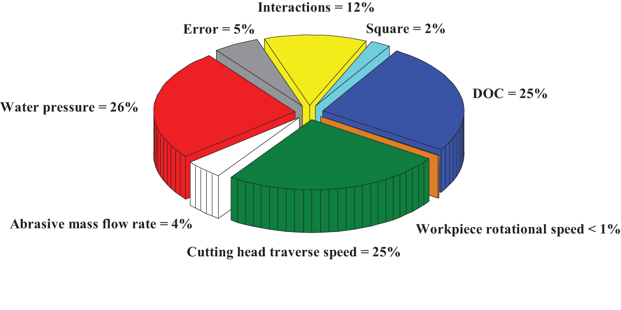
Percent contribution of AWJT model effects.
Response contour plots of the geometrical error are illustrated based on the response regression equation in coded factors (equation (5)). The effects of two significant factors are investigated simultaneously, while other factors are kept constant at their middle levels.
Figure 7 shows the contour plot of the geometrical error response with respect to the water pressure and the workpiece traverse speed at constant levels of workpiece rotational speed (400 r/min), abrasive mass flow rate (5.24 g/s) and DOC (3 mm). It illustrates that a geometrical error reduction is generally obtainable by decreasing the workpiece traverse speed and increasing the water pressure. An increase in the traverse speed causes a decrease in the jet exposure time with the surface of the workpiece. Lesser abrasive particles impact the surface, and the removed volume from the periphery of the workpiece decreases. According to Bernoulli’s law and the momentum transfer from water to the abrasives, higher pressures produce more energy and more acceleration of abrasive particles. This condition results in higher erosion rate during the limited exposure time and reduces the workpiece diameter more.
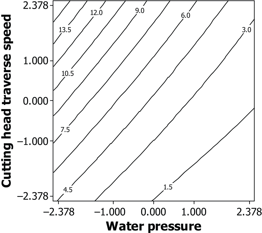
Effect of pressure and traverse speed on the geometrical error (
Figure 8 displays three-dimensional (3D) surface and contour plot of the geometrical error response in relation to the water pressure and DOC, while other parameters are kept constant at their middle levels. The opposite effect of DOC and pressure on geometrical error is noticeable in the hyperbolic paraboloid (saddle) response surface. Higher DOC results in higher geometrical error due to more material to be eroded 2 and jet instability.10,12 Higher pressures reduce the geometrical error as discussed in Figure 7. At the saddle point, the effect of each parameter compensates the opposite effect of the other one. In this condition, keeping the water pressure constant and increasing or decreasing the DOC lead to reduction in the geometrical error. In turning at high depths of cut, if the jet energy is high enough (high pressures), it is possible to turn the workpiece until reaching a similar condition to turn at low depths of cut. Thus, the produced parts at high and low depths of cut have almost the same geometrical error. Instead, if the water pressure decreases, it is not sufficient to efficiently erode the whole material volume. So, increasing DOC at low pressures increases the geometrical error.
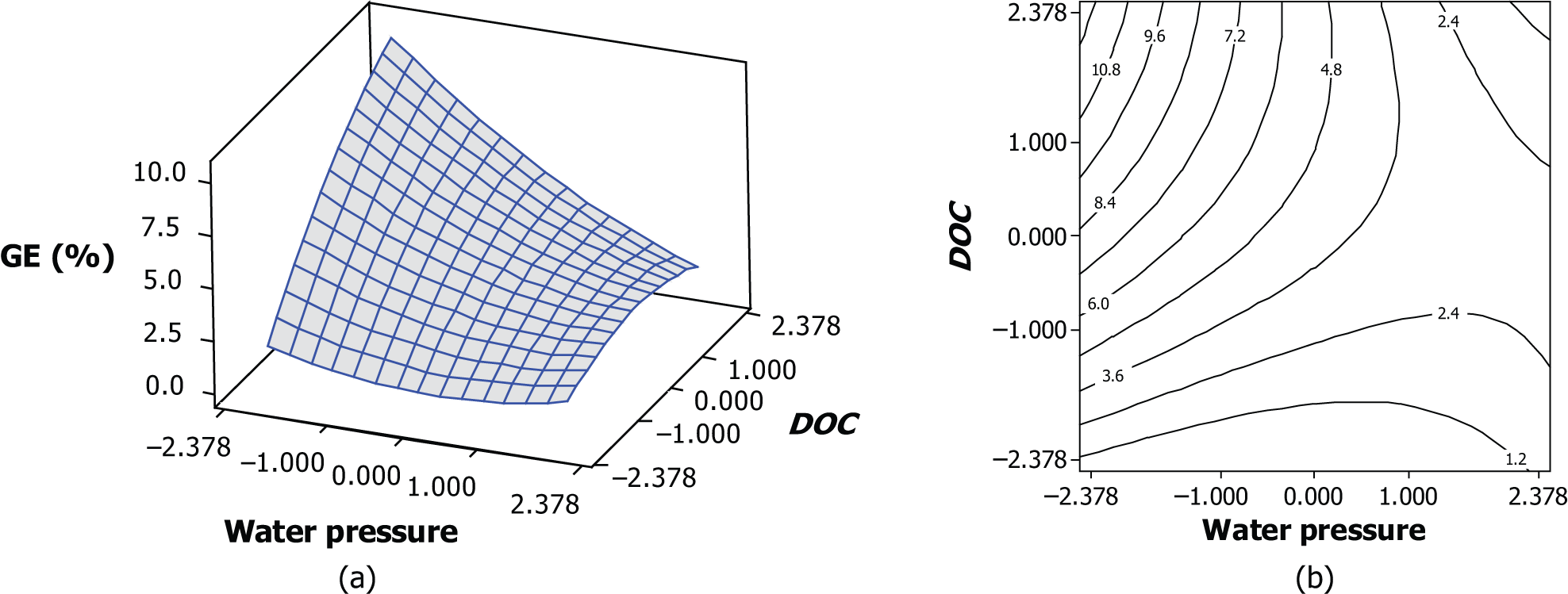
Effect of pressure and depth of cut on the geometrical error (
The effects of abrasive mass flow rate and traverse speed on the geometrical error are illustrated as contour plot in Figure 9. It is concluded that lower geometrical error is achievable at high abrasive mass flow rates and low traverse speeds. Additionally, at high traverse speeds, the effect of abrasive mass flow rate on reducing the geometrical error is higher than when machining at low workpiece traverse speeds. Similar results were reported by Ansari. 2
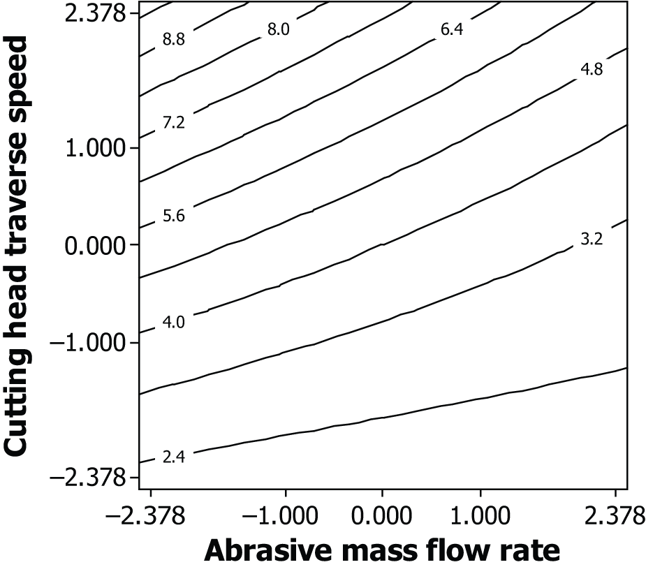
Effect of abrasive mass flow rate and traverse speed on the geometrical error (P = 250 MPa, DOC = 3 mm and N = 400 r/min).
The simultaneous effects of abrasive mass flow rate and DOC are depicted in Figure 10. In agreement with the previous research by Ansari, 2 increasing abrasive mass flow rate and decreasing DOC reduce the geometrical error. It is worth noting that increasing the abrasive mass flow rate while machining at low depths of cut does not have a meaningful effect on the geometrical error. It means that the material that must be eroded is low enough than higher abrasive mass flow rate, which implies that higher erosion rate is not utilized effectively in the material removal.
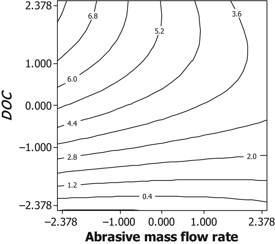
Effect of abrasive mass flow rate and depth of cut on the geometrical error (P = 250 MPa, u = 5 mm/min and N = 400 r/min).
The effects of pressure and abrasive mass flow rate on the geometrical error, while other parameters are kept constant, are demonstrated in Figure 11. Increasing pressure and abrasive mass flow rate leads to a reduction in the geometrical error. At low pressures, variations in abrasive mass flow rate almost have no effect on the geometrical error, while at high pressures abrasive particles are accelerated enough to turn the part with closer tolerances. These findings confirm the previous investigations by Ansari and Hashish.2,3,29
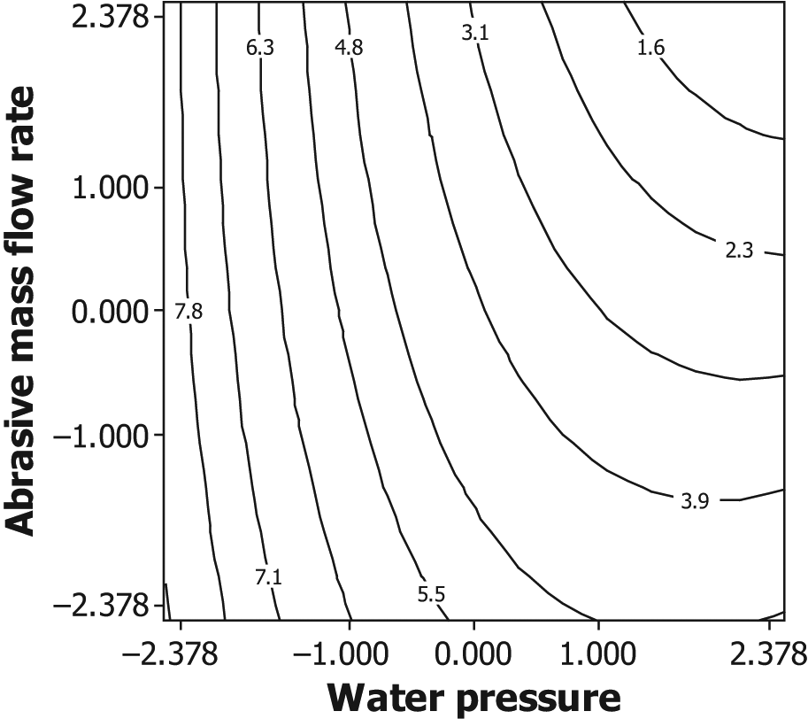
Effect of pressure and mass flow rate on the geometrical error (DOC = 3 mm, u = 5 mm/min and N = 400 r/min).
Figure 12 shows contour plot of the geometrical error response with respect to traverse speed and DOC at constant levels of pressure, abrasive mass flow rate and rotational speed. It illustrates that for higher depths of cut, decreasing traverse speed can highly reduce geometrical error. However, decreasing traverse speed increases the time of machining. In practice, turning parts at low DOC and high traverse speed in multi-passes can be a practical way to increase the process efficiency.
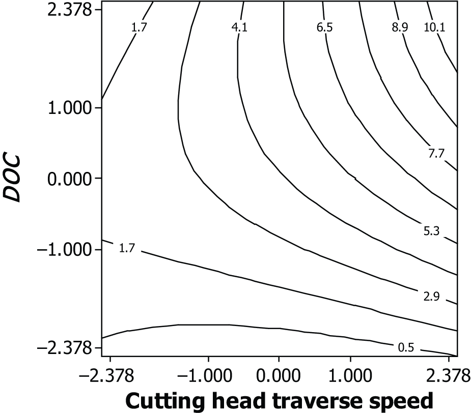
Effect of traverse speed and depth of cut on geometrical error (P = 250 MPa,
Conclusion
An experimental study was conducted to investigate the effects of major process parameters and their interaction on geometrical error in AWJT. A five-level experimental design was carried out based on CCRD. The main effects of parameters and also the interaction between them were analyzed based on an ANOVA. It is found that among the input process parameters, pressure, abrasive mass flow rate, traverse speed and DOC are significantly effective, while workpiece rotational speed has not so significant effect on the geometrical error of AWJ turned parts. Pressure, traverse speed and DOC were detected as the most significant parameters with almost the same percentage of contribution. Workpiece rotational speed is the least significant parameter. In addition, interactions between pressure and traverse speed, pressure and DOC, abrasive mass flow rate and DOC and traverse speed and DOC were found to be significant. Besides, a mathematical model for relationship between the process parameters and geometrical error response has been presented based on a quadratic regression. The model could successfully predict the geometrical error of AWJ turned parts.
This study activates a potential to improve the precision of AWJT. This requires further investigations to examine reducing geometrical error in relation to improvement in MRR and surface quality.
Footnotes
Declaration of conflicting interests
The authors declare that there is no conflict of interest.
Funding
This research received no specific grant from any funding agency in the public, commercial or not-for-profit sectors.