
Abstract
This paper aims to develop a finite element (FE) model precisely simulating the multi-particle impact in the radial mode abrasive waterjet turning (AWJT). An explicit dynamic analysis was carried out to predict the crater profile resulting from the impact of the abrasive particles along a limited segment of the jet pass over the workpiece surface. The effect of both momentum transfer loss and abrasive load ratio was taken into consideration while calculating the impact velocity of the abrasive particles. To build a user-friendly model, the scripting feature of ABAQUS was involved to automatically perform all the repetitive modeling procedures. The presented FE model considers four variable turning parameters tested at five levels each, including impact velocity, abrasive mass flow rate, traverse rate, and workpiece speed. The obtained crater profile from the simulation process was utilized to calculate the depth of cut (DOC) at different parameter combinations. A comparison between the numerical and experimental results shows a good agreement with an average absolute relative error of 9.74%.
Keywords
Introduction
Abrasive waterjet (AWJ) is an advanced machining technology that employs a waterjet to accelerate the abrasive particles towards the workpiece. The waterjet is usually pressurized up to 620 MPa so that the abrasive particles can strike the target surface at a velocity between 300 m/s and 1000 m/s. Almost all the earlier theories and practices confirmed that the material removal in AWJ occurs based on the erosion principle. 1 AWJ machining is featured by high versatility, negligible cutting forces in the range 40–80 N, no heat-affected zone due to low temperatures in the range 10–40°C, simplicity of workpiece fixturing, and little burr formation. Therefore, it can machine difficult to cut, heat-sensitive and fragile materials, most notably ceramics, composites, Inconel, titanium alloys, and glass. 2 AWJ was initially utilized for linear cutting of plates, but it has kept evolving to performing controlled depth processes such as milling and turning. 3 Hashish 4 reported that abrasive waterjet turning (AWJT) can efficiently turn carbide-metal composites, glass, and ceramics. This process exploits the eroding action of AWJ to produce axisymmetric workpieces using the same principles of centre lathe turning where the AWJ replaces the traditional tool insert. According to the positioning mechanism of the AWJ nozzle with respect to the workpiece, AWJT is subdivided into radial or offset mode, as shown in Figure 1. Li et al. 5 pointed out that the radial mode is more efficient based on the rate of material removal since it allows the maximum utilization of the AWJ energy. Liu et al. 6 were able to achieve a higher material removal rate (MRR) up to 28% using the radial mode turning of alumina ceramics at the same turning conditions. On the other hand, the offset mode can provide better surface quality and easier control of the cutting depth.
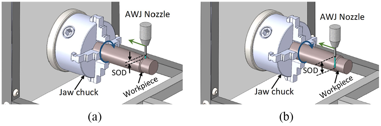
A schematic diagram of AWJT modes: (a) radial mode and (b) offset mode.
Several experimental studies have investigated the effect of the process parameters on the performance of AWJT. Hlaváček et al. 7 demonstrated the superiority of AWJ over the conventional techniques in turning cylindrical parts of sandstone. Nag et al. 8 confirmed the potency of AWJT in turning metal matrix composites due to the absence of changes in the microstructure or physical properties. Hlavacek et al. 9 clarified the significant effect of the rotation direction and abrasive type on the final diameter and surface roughness in the offset mode turning of Ti6Al4V. Ibrahim et al. 10 introduced the submerged AWJT technique that was useful for reducing the noise levels up to 20%. Cárach et al. 11 presented an empirical model to relate the process parameters to the surface roughness in the offset-mode of Monel K-500. Kartal et al. 12 employed the experimental design method to optimize the performance of the offset mode AWJT of low-density polyethylene. Manu and Babu 13 developed an analytical model based on Finnie’s erosion model for ductile materials, that could predict the final workpiece diameter under different levels of traverse rates and radial jet positions. Li et al. 14 created a semi-empirical model based on the Buckingham π theorem to predict the DOC in radial mode AWJT of AISI 4340. Yue et al. 15 combined the response surface methodology and sequential approximation optimization for optimizing the radial mode AWJT. Zohoor et al. 16 presented a quadratic regression model to examine the effect of process factors on the geometrical error in the offset mode turning of AA2011-T4 aluminum alloy.
The finite element method (FEM) was frequently used in the modeling of single and multi-particle impacts under AWJ machining conditions. The single-impact based models were utilized for many purposes. Anwar et al. 17 investigated the aspects of controlled depth machining in AWJ technology using the output crater profile. Li et al. 18 studied the response of ductile steel material due to the impact of a micro-abrasive particle. Lv et al. 19 proposed an explicit dynamic model to investigate the erosion rate in ultrasonic-assisted abrasive waterjet machining. Liu et al. 20 created a finite element (FE) model to estimate the resulted MRR during the high-velocity impact of a single abrasive particle. Two variable parameters were involved in the simulations: abrasive particle velocity and impingement angle. The comparison between the predicted and experimental results showed an average error of about 15%. Most of the previous FE models were similar in that both the impacting angle and velocity were the only considered process variables. Besides, the impacting particle was modeled using a spherical rigid body for simplicity.
More advanced models were inevitable to simulate the overlapping impacts while considering more realistic conditions and realizing the real removal mechanisms. Hence, the multi-impact models were also developed and utilized for many purposes. Li et al. 21 proposed a FE model to analyze the erosion behavior in AWJ machining of AISI 4340. The simulations considered three levels of traverse rate and two levels of impact angles with a constant abrasive mass flow rate of 3 g/s and waterjet pressure of 400 MPa. Anwar et al. 22 presented the first attempt to employ the real size and shape distribution of particles while modeling the footprints of the AWJ milling process. They demonstrated that only 82% of the abrasive particles are effective on the rate of material removal while using abrasive garnet #80. A new term “particle mix” was introduced to express a set of nineteen garnet particles that have a similar quality as the real particles in AWJ machining. The FE simulations considered three levels of waterjet pressure up to 276 MPa, and two levels of traverse rate, and a single level of abrasive mass flow rate at 0.33 g/s. Torrubia et al. 23 carried out an investigation to simulate the AWJ footprints resulting from either single or overlapped jet passes. The only process parameters included in the numerical investigation were nozzle diameter, traverse rate, and impact angle. Both waterjet pressure and abrasive mass flow rate were kept constant at 138 MPa and 0.5 g/s, respectively. Nyaboro et al. 24 developed a numerical model based on computational fluid dynamics and FEM to simulate AWJ drilling of carbon fiber reinforced polymers. Their results revealed the mechanisms of delamination in carbon fiber reinforced polymers machined by AWJ. Abdelhameed et al. 25 simulated the multiple-impacts in AWJT to investigate the crater geometry in the radial-mode of AWJT. They investigated the effect of both the traverse rate and jet impact angle using three levels for each factor. One drawback of the discussed multiple-impact models is simulating the AWJ machining over a limited range of parameters. Another drawback is neglecting the effect of both the waterjet pressure and abrasive mass flow rate on the momentum transfer. Meanwhile, these models introduced new methodologies to assign the shapes and sizes of the impacting particles instead of using spherical bodies.
The present paper aims to extend the previous FE work in order to create a user-friendly model precisely simulating the erosion process in AWJT under realistic conditions. The current FE model investigated the radial mode AWJT to facilitate the precise control of DOC in this efficient mode. The effect of the process factors on momentum transfer was taken into account during the calculation of the impact velocity.
Finite element model description
A three-dimensional (3D) model was built and assembled to simulate the impact of the abrasive particles over a limited portion of the jet pass, as shown in Figure 2. The aim of that present model is to calculate the DOC using the resulting geometry of the crater. The FE model was developed using ABAQUS (version 6.14-1) where the explicit dynamic module was involved because of its ability to solve high-speed impact problems. The scripting feature of ABAQUS was employed to create an automatic and user-friendly model to reduce the modeling time and efforts.
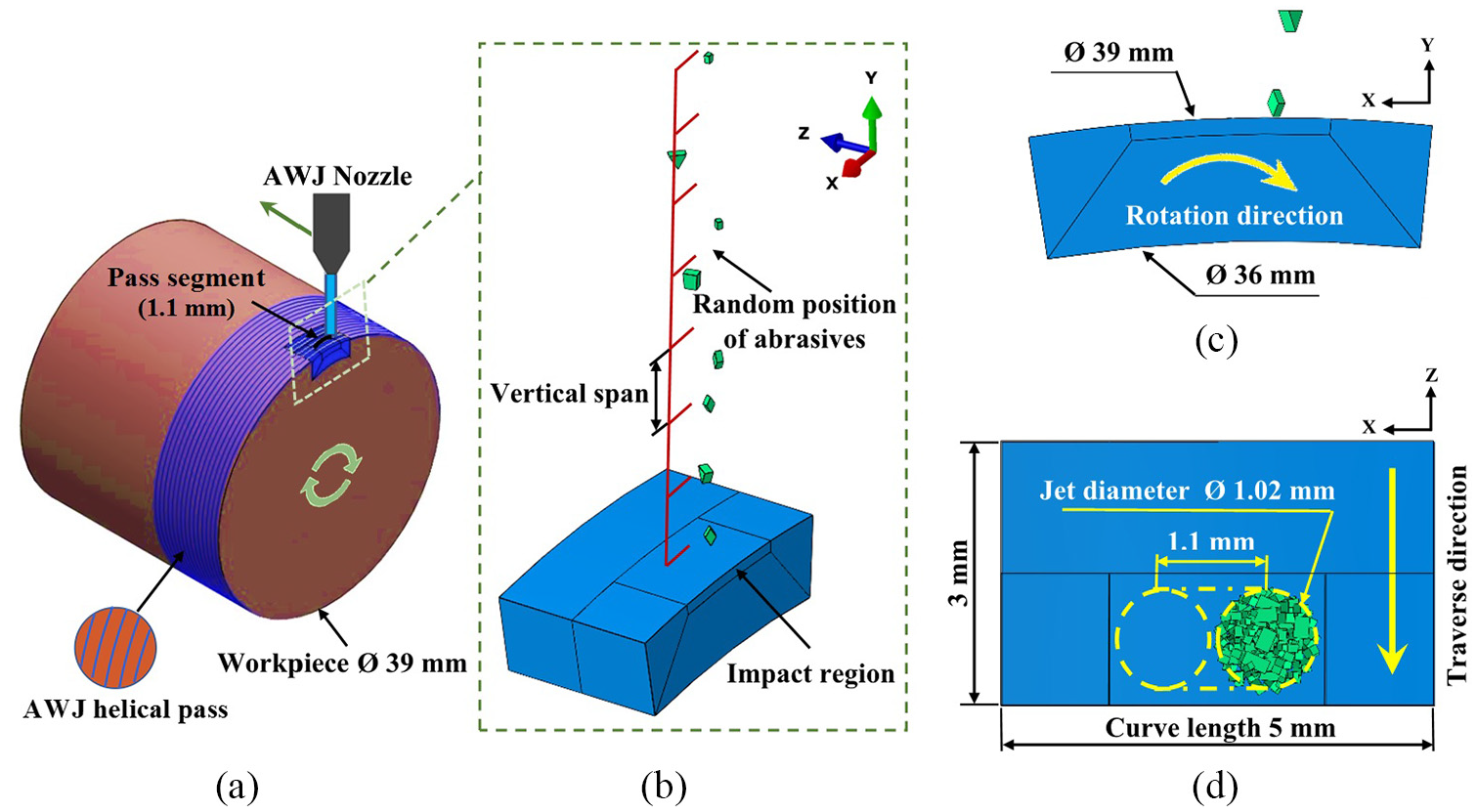
Model assembly: (a) a schematic for the radial mode turning, (b) 3D view of the FE model assembly, (c) elevation view, and (d) plan view.
Model geometry and assembly
Abrasive particle distribution
Dong et al.
26
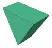
reported that the amount of removed material due to an impact depends on the shape and orientation of the impacting particle. Generally, the abrasive particles possess many geometric shapes like spherical, triangular, rectangular, rhombic and trapezoidal.
1
In the present study, the same particle mix found in the literature
22
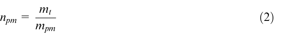
was involved. Table 1 shows the characteristics of nineteen particles of this particle mix. For modeling and positioning the abrasive particles, the total abrasive mass
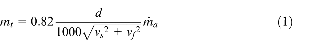
Where
where
where
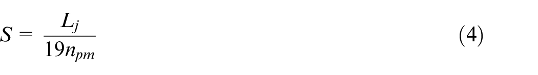
Abrasive particles characteristics in a particle mix. 22
Model geometry
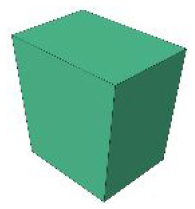
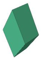
The workpiece was 3D modeled using a cylinder segment shape with an outer diameter of 39 mm, inner diameter of 36 mm, segment angle of 14.69° and cylinder width of 3 mm, as in Figure 2. The crater profile produced from the simulation is the result of many overlapped jet footprints in the movement direction. To achieve a stable depth region, the workpiece should be allowed to rotate by a specific angle so that the jet can cover a distance larger than the jet diameter, as presented in Figure 3.
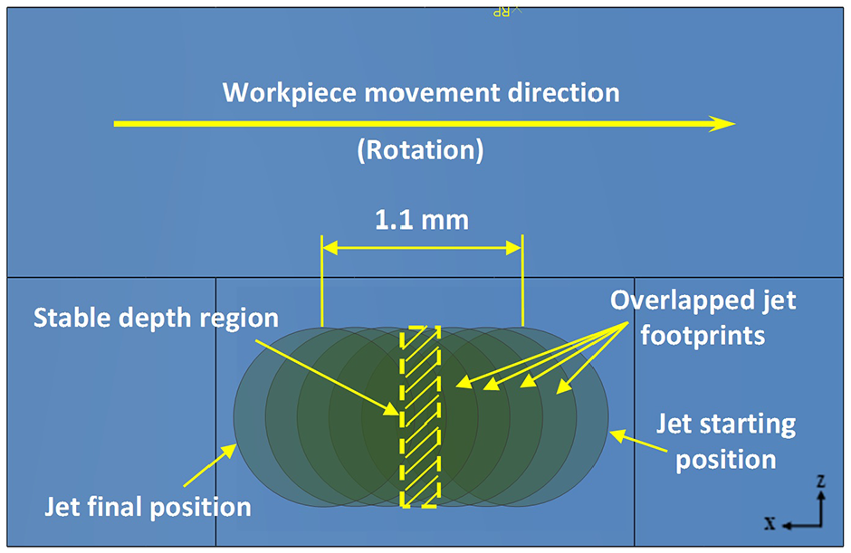
A schematic showing the overlapped jet footprints (plan view).
Material modeling
Workpiece material
In the current study, the workpiece material (AISI 4140) is expected to exhibit high strain rates up to 106 s−1 under AWJ machining conditions.
27
Therefore, the empirical model developed by Johnson and Cook
28
was employed to describe the behavior of workpiece material where von Mises flow stress
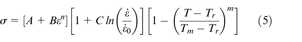
Where
The damage model proposed by Johnson and Cook 29 is capable of accurately expressing the fracture behavior of ductile materials at high levels of strain rates. This model is based on the equivalent plastic strain criterion in which the equivalent plastic strain rate at fracture is determined by the following equation:
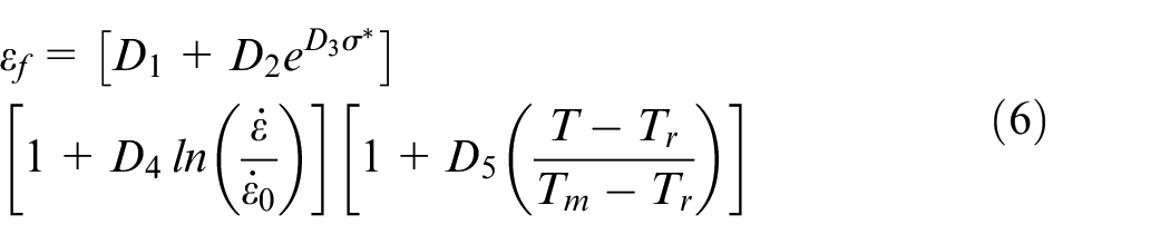
Where
where
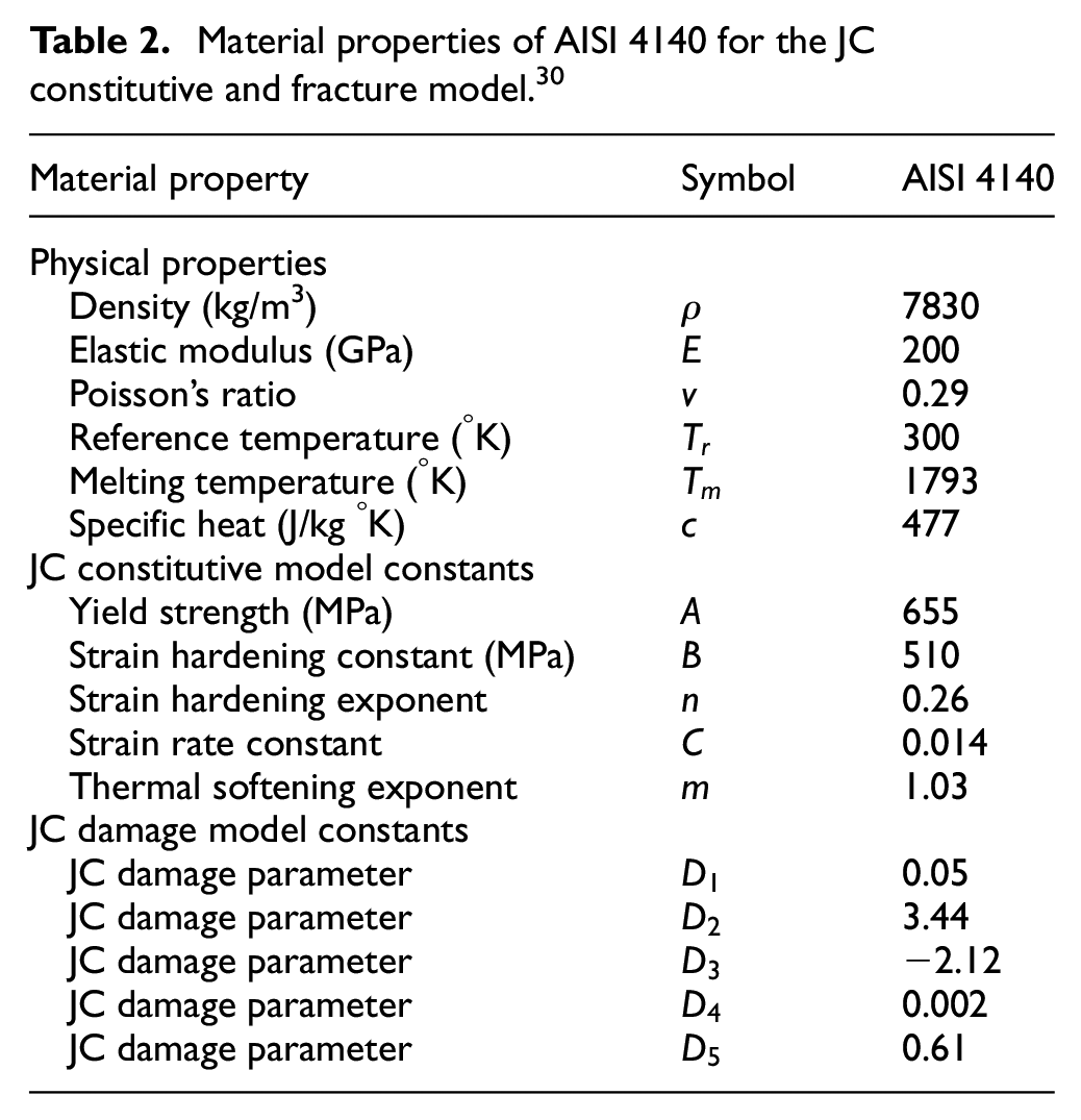
Material properties of AISI 4140 for the JC constitutive and fracture model. 30
Abrasive material
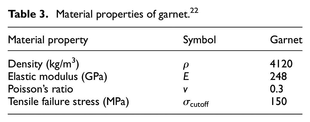
It was reported that abrasive particles are exposed to fracture as a result of the impacting forces in the AWJ machining process. 31 The tensile failure model was utilized in the present work to define the garnet material using the constants shown in Table 3.
Material properties of garnet. 22
Meshing
The mesh size was iteratively refined until obtaining adequate results. The workpiece mesh was refined in the impact region where the element size was 16 × 7 × 16 µm3, as shown in Figure 4. All the elements of abrasive particles were the same size with an edge length of 25 µm. Linear 3D stress elements (C3D8R) with hourglass control were assigned for both the workpiece and abrasive particles. The element deletion option was activated to allow the removal of the damaged elements from the mesh.
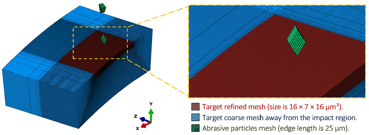
Meshing of the workpiece and abrasives.
Contact mechanism
The interaction between the workpiece and abrasive particles was defined by the general contact mechanism in ABAQUS. An element set for all interior surfaces was created in ABAQUS/CAE interface, and the input file was edited to allow the interior surfaces inclusion in contact. The nodal erosion control was added to the contact algorithm to remove the remaining contact nodes after the deletion of failed elements. The tangential interaction property was assigned using the penalty formulation with a friction coefficient of 0.1.
Boundary conditions
Workpiece
The kinematic coupling constraint was introduced to allow the workpiece rotation. By this method, four workpiece surfaces were restrained with the target center point while keeping the nodes of the upper and front surface free, as illustrated in Figure 5. The reference point was free to move only in two degrees of freedoms: rotation about the negative z-axis and translation in the negative direction of the same axis.
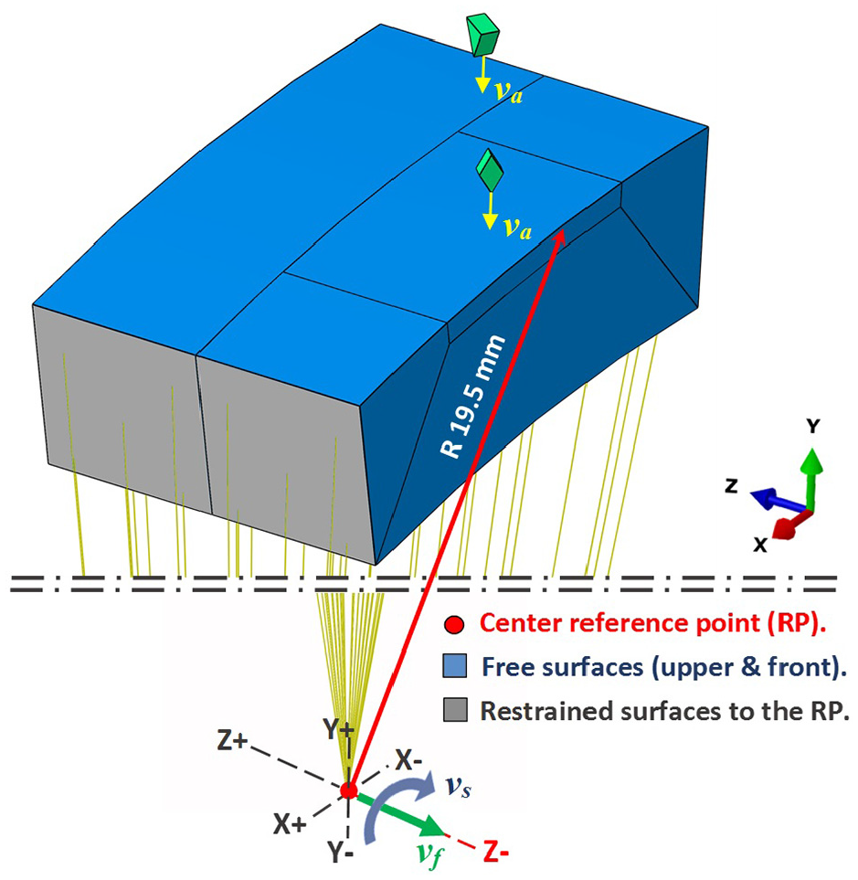
Interactions and boundary conditions.
Abrasive particles
It was demonstrated by Momber and Kovacevic
1
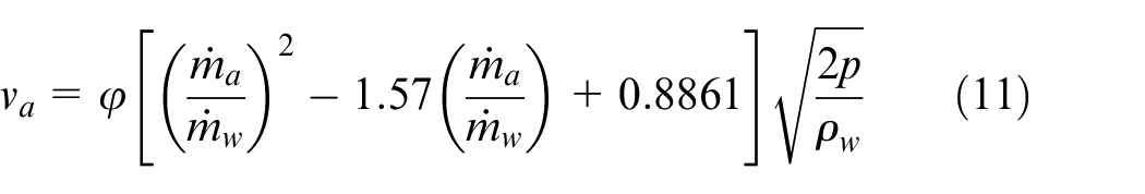
that Bernoulli’s equation is valid for estimating the theoretical waterjet velocity, and that the effective waterjet velocity
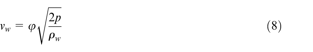
where
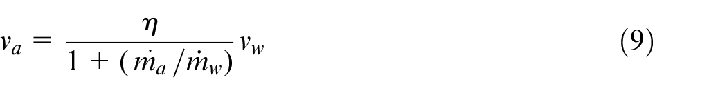
where
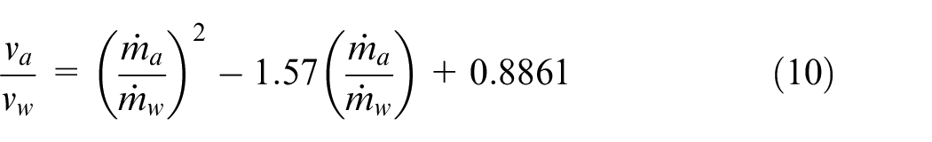
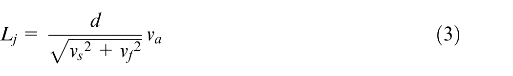
The general relationship between the impact velocity of the abrasive particles and the waterjet pressure can be given by:
ABAQUS scripting
ABAQUS scripting is an interesting feature that enables its user to exploit the power of the Python programming language to automatically execute the modeling actions through a group of commands. In the present work, all the modeling procedures were recorded to generate the subroutine files containing their corresponding commands. These subroutines were modified to allow the automatic repetition of modeling tasks. Another program called IDLE Python 3.5 was utilized to test the main programming algorithms and to edit the final compiled subroutine before being executed.
Experimental work
Materials and specimens
AWJT machining experiments were conducted on cylindrical specimens of AISI 4140 alloy steel to validate the results of the FE model. All the specimens were turned to the dimensions of Ø 39 mm × 70 mm. Indian Garnet with #80 mesh size and an average diameter of 180 µm was used as the abrasive agent in the experiments. The length of cut was 10 mm along the workpiece axis within all tests.
Experimental setup
A special turning fixture was manufactured and mounted on a four axis CNC AWJ machine (Suprema 620), as shown in Figure 6. A KMT pressure intensifier with a maximum water consumption rate of 5.5 l/min and operating pressure up to 620 MPa was used. The cutting head of the AWJ machine was equipped with a nozzle of 1.02 mm diameter. Nozzle SOD was kept constant at 3 mm in all the experimental tests. For each test, the final workpiece diameter was measured at three different positions using a Mitutoyo Digimatic outside micrometer of 0.001 mm then the average values were taken.
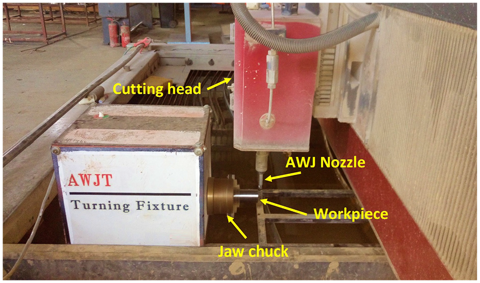
AWJT experimental setup.
Experimental design
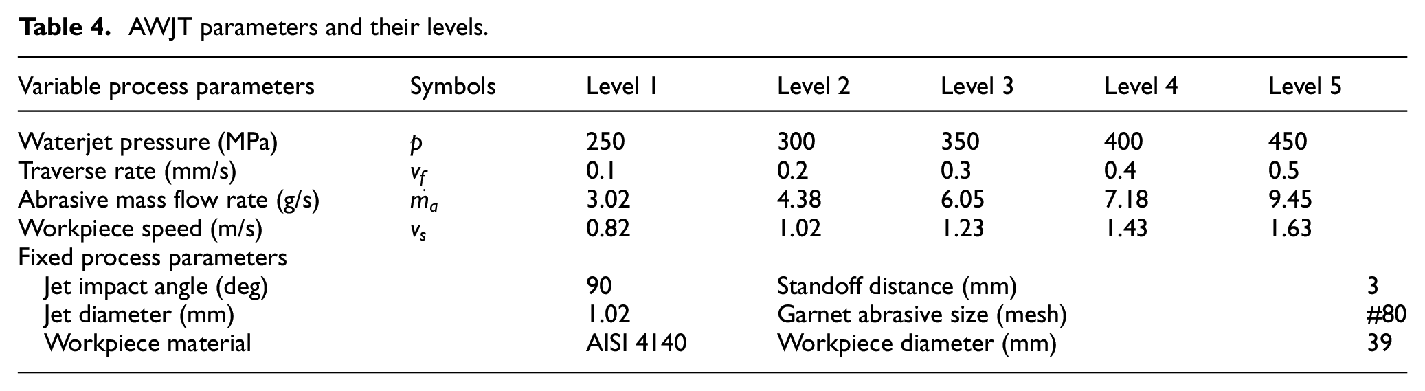
Most of the previous experimental studies showed that waterjet pressure, traverse speed, and abrasive mass flow rate have the greatest effect on the DOC in AWJT. Therefore, these three parameters along with the surface speed of the workpiece were considered in the present FE study. Each parameter was tested at five levels, as shown in Table 4. To reduce time and cost of both experimental and numerical procedures, a Taguchi et al. 34 orthogonal design can be adopted to study the process parameters effect with less number of experiments. Thus, a standard L25 orthogonal array was employed to design the experiments plan.
AWJT parameters and their levels.
Results and discussion
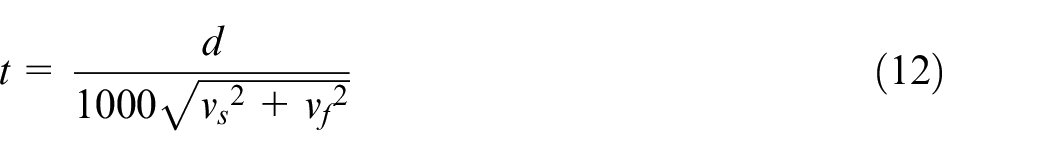
A total number of 45 models were created in ABAQUS/CAE interface. It took only from 30 to 150 s to complete the entire modeling procedures for each model. The simulations were conducted on a desktop computer with an Intel® Core™ i7-4790K (4.4 GHz) processor and 32 GB RAM, running under a 64-bit operating system (Windows 10 Professional). The problem size was in the range between 1.6 e 6 and 2.2 e 6 degrees of freedom, and it took from 18 to 27 h on average to complete the simulation process in each run. It should be noted that the simulation step time was obtained according to following equation:
Effect of AWJT parameters on the erosion rate
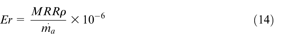
In this section, the effect of tested parameters on the erosion rate was studied to provide an inclusive overview of the erosion process in AWJT. The influence of each parameter on the erosion rate was individually analyzed while keeping the other parameters constant at their mid-values. This investigation was conducted using two different strategies. In the first one, the number of deleted elements within the impact region was counted by employing the ABAQUS report files. These counted numbers were utilized to calculate the material removal rate (mm3/s) at different intervals of the simulation time as follows:
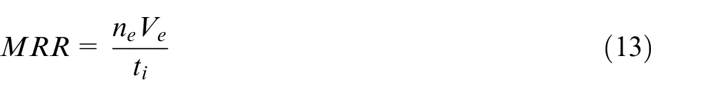
Where
In Figures 7 to 10, it can be observed that the erosion rate grows exponentially from zero at 0% time until reaching its final stable value. Therefore, it can be deduced that single- or limited multi-impact models cannot precisely express the erosion process under AWJ machining conditions. Figure 7 shows that the erosion rate is continuously rising as the waterjet pressure increases. The erosion rate is greatly enhanced by 0.0216 g/g (197.96%) as the pressure changes from 250 to 450 MPa. This increasing trend becomes sharper as the impact efficiency of the abrasives gets improved at higher pressures.
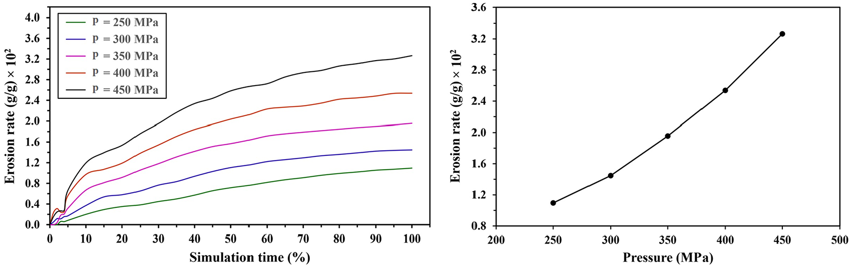
Variation of erosion rate with different waterjet pressures.
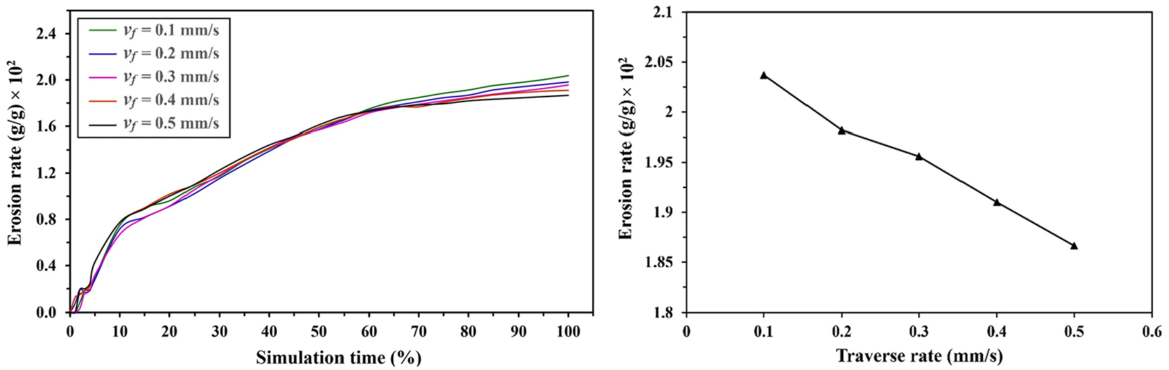
Variation of erosion rate with different traverse rates. p = 350 MPa,
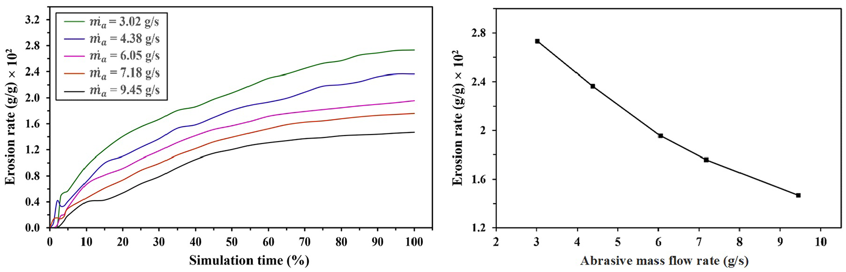
Variation of erosion rate with different abrasive mass flow rates. p = 350 MPa,
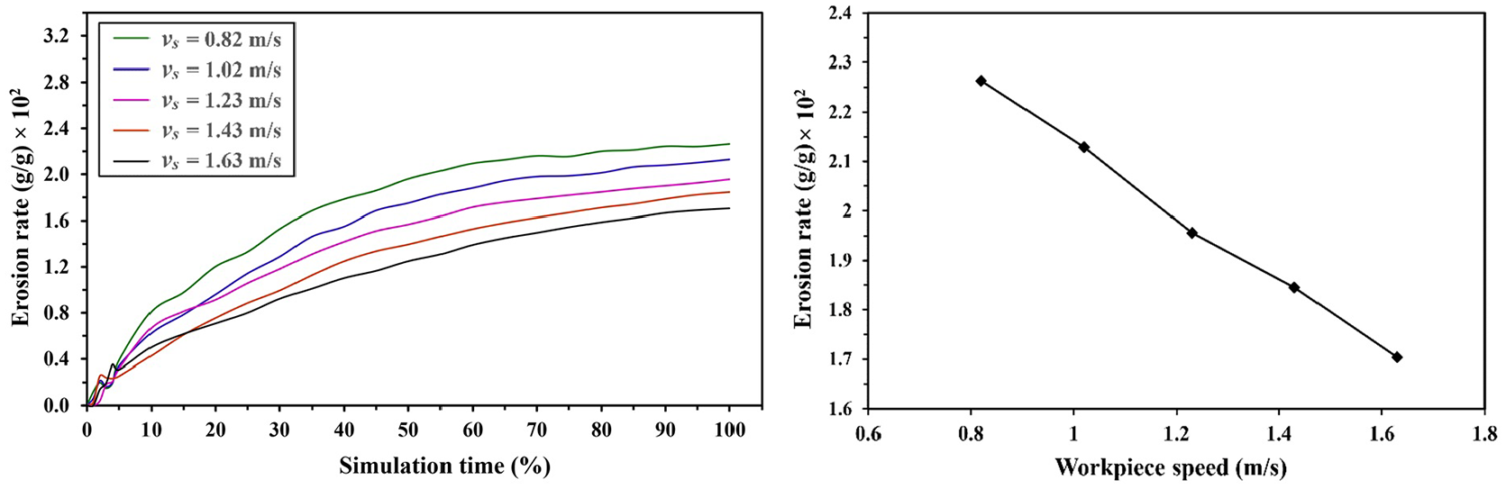
Variation of erosion rate with different workpiece speeds. p = 350 MPa,
Figure 8 indicates that as the traverse rate goes up, the erosion rate declines. An increase in the traverse rate from 0.1 to 0.5 mm/s would decrease the erosion rate by 0.0017 g/g (8.37%). This decreasing trend arises because the overlapping intensity of the neighboring impacts is reduced when increasing the traverse rate. Figure 8 also reveals that erosion rate trends at different traverse rates keep interfering until reaching 70% of the simulation time at which the difference between them gets more manifested.
Despite that an increase in MRR of 7.18 mm3/s (68.17%) was found upon rising the abrasive mass flow rate from 3.02 to 9.45 g/s, a drop of 0.0126 g/g (46.26%) was obtained in the erosion rate, as shown in Figure 9. Whereas the increasing trend of MRR could not neutralize the inverse effect of the abrasive mass flow rate on the erosion rate. Thus, the impact efficiency of the abrasive particles goes down at higher abrasive mass flow rates.
Figure 10 presents the effect of the workpiece speed on the erosion rate. It was observed that doubling the workpiece speed from 0.82 to 1.63 m/s would result in a fall of 0.0056 g/g (24.74%) in the erosion rate.
A second strategy was adopted to examine the erosion rate by using the eroded crater area in the stable depth region. A crater with a stable geometry can be achieved in the region at which the largest possible number of interfered impacts occurs. Figure 11(a) and (b) illustrates that the crater depth is gradually increasing until reaching its stable region. The stable crater geometry truly expressing the erosion rate could be extracted only from this region, as shown in Figure 11(c). Assuming that the crater area is constant along the jet pass, MRR (mm3/s) can be estimated as follows:
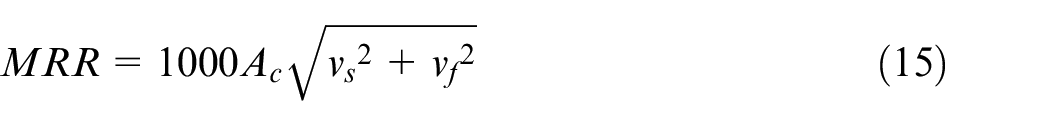
where
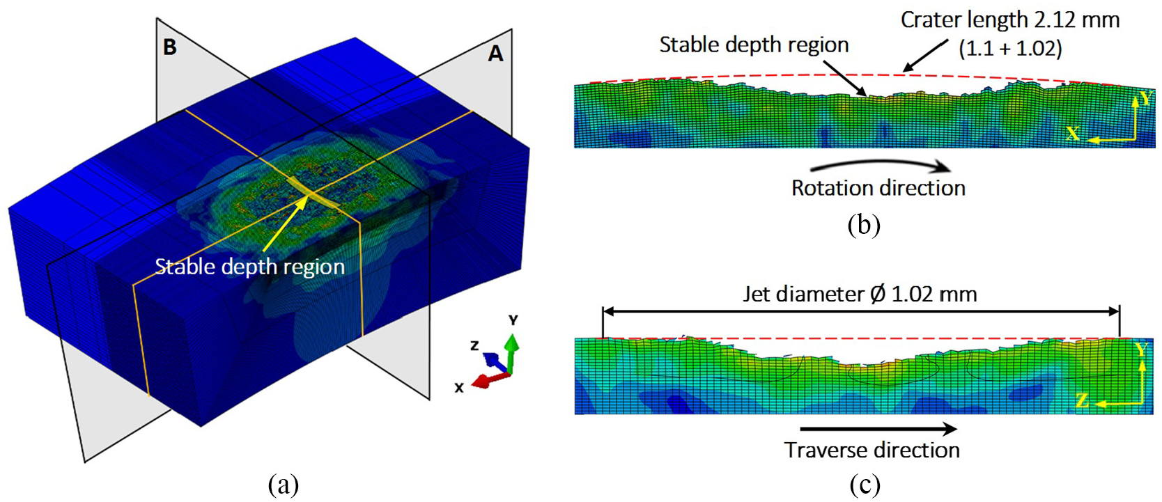
(a) 3D multiple cuts of the obtained crater profile, (b) zoomed in cross sectional elevation view at section A, and (c) zoomed in cross-sectional side view at section B.
Figure 12 shows a comparison that illustrates the difference between the erosion rates calculated by the two strategies. It can be concluded that the erosion rate obtained by utilizing the number of deleted elements within the second strategy is greater than that obtained using the first strategy with a percentage in the range of 4%–11%. In addition, the erosion rate calculated while considering the crater deformations always has the greatest value and is mostly the closest to the exact erosion rate. It can be observed that the relative percentage between the two erosion rates from the second strategy increases from 85.9% to 95.2% by increasing the pressure from 250 to 450 MPa. Hence, fewer deformations are to be found at higher pressures due to the occurrence of material failure at higher strain rates. On contrary, changing the traverse rate does not significantly affect the relative percentage between that two erosion rates. It was also found that increasing the abrasive mass flow rate from 3.02 to 9.45 g/s would increase the relative percentage between the two erosion rates from 86.02 to 93.08%. This indicates that the final crater profile is less deformed at a larger number of overlapped impacts. Finally, an increase in the workpiece speed from 0.82 to 1.63 m/s decreases the relative percentage from 93.6% to 91.4%.
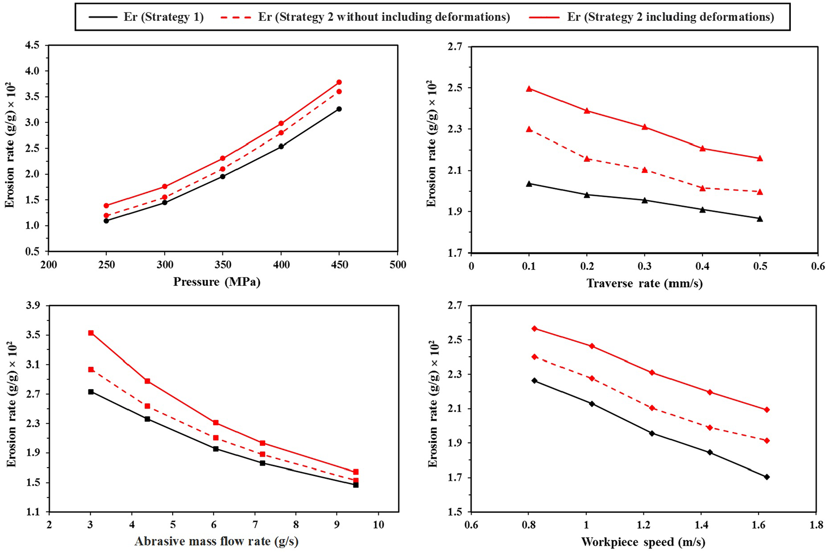
Comparison of the erosion rates by the two proposed strategies under different AWJT conditions. Constant parameters conditions: p = 350 MPa,
Experimental verification of the FE model
The DOC was estimated using the MRR calculated from the resulting deformed crater in the stable region as follows:

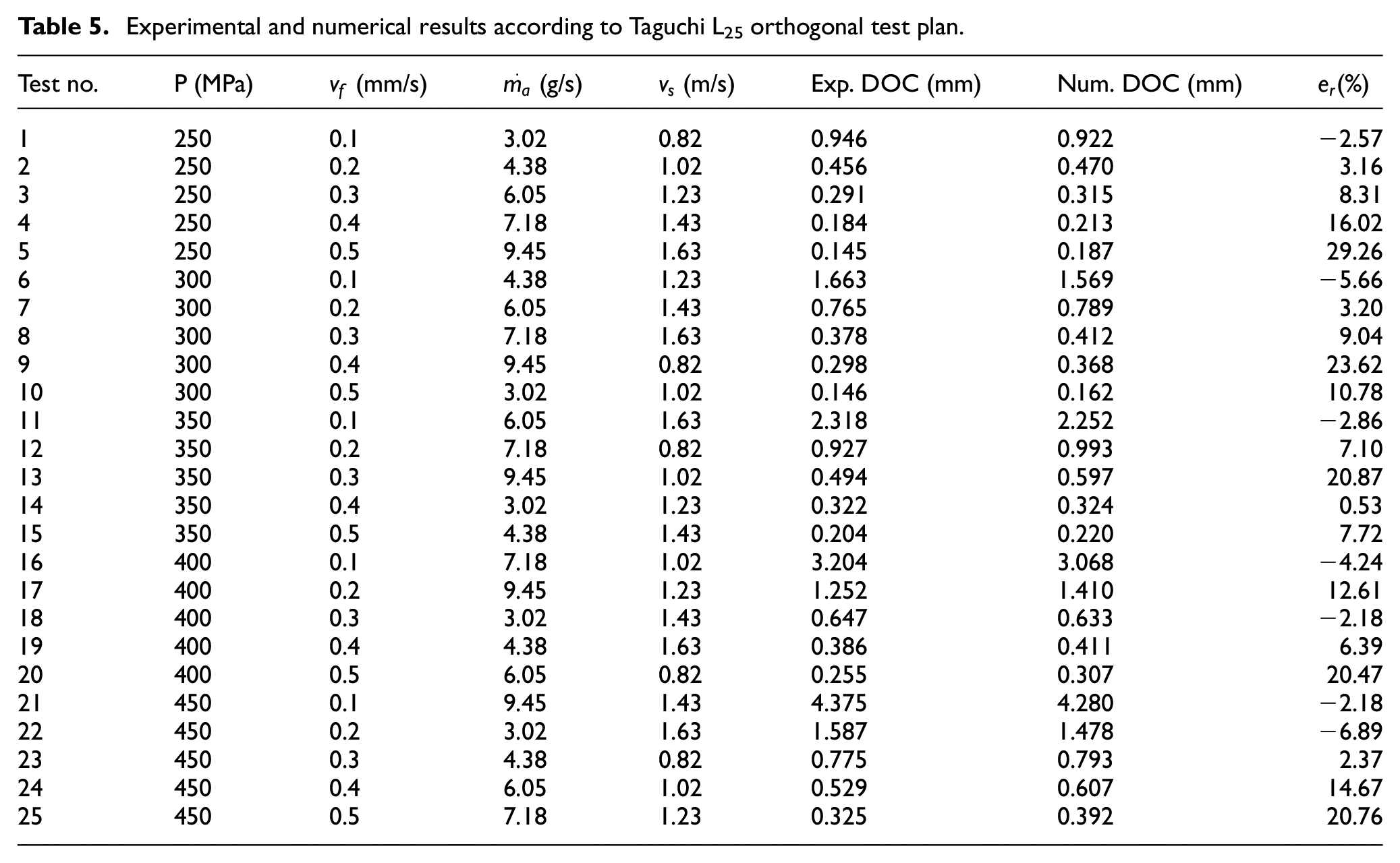
The model accuracy was then evaluated by comparing the numerical and experimental data of DOC under the same machining conditions, as presented in Table 5. The maximum and minimum values of absolute relative error were found to be 29.26% (0.042 mm) and 0.53% (0.002 mm), respectively. A high level of prediction accuracy was achieved with an average absolute error of 9.74%.
Experimental and numerical results according to Taguchi L25 orthogonal test plan.
Analyzing the experimental results
Figure 13 demonstrates the effect of input parameters chosen for the experimental analysis on the measured response factor (DOC). It can be observed that increasing the waterjet pressure from 250 to 450 MPa would increase the DOC by 300%. On the other hand, the DOC decreases by 91% after increasing the traverse rate from 0.1 to 0.5 mm/s. A higher DOC of 80% is obtained when increasing the abrasive mass flow rate from 3.02 to 9.45 g/s. It can be demonstrated that a non-uniform increasing trend in the DOC occurs when increasing the workpiece speed.
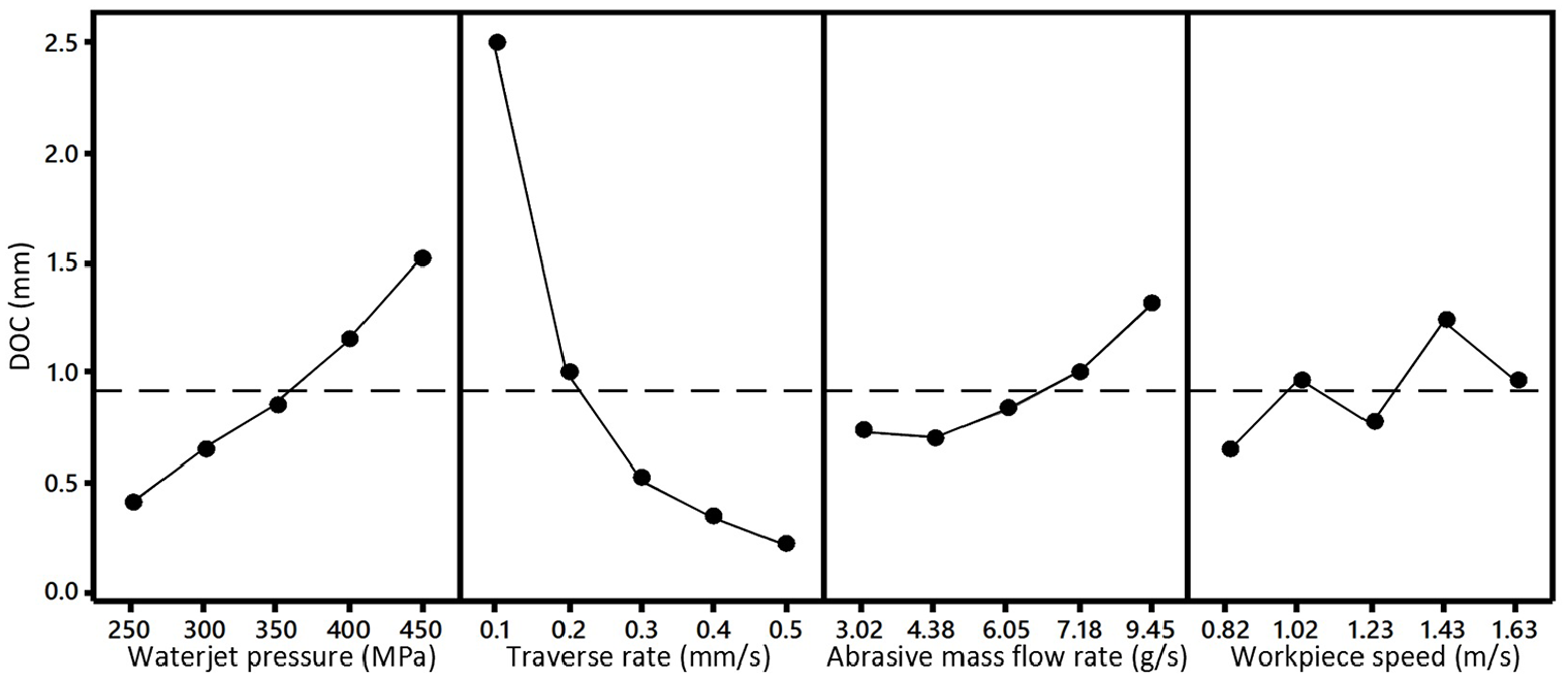
Main effect plot for means of DOC.
Table 6 shows the results of the ANOVA test which was carried out at a 95% confidence level. It is seen that traverse rate and waterjet pressure are the most significant factors on DOC, respectively. It is also noted that abrasive flow rate and workpiece speed have a negligible significance on the DOC since they have P-value higher than 0.05. The ANOVA table demonstrates that the highest factor contributing the response factor is traverse rate by 80.9% trailed by waterjet pressure over 17.9%.
Analysis of variance for S/N ratios of DOC.
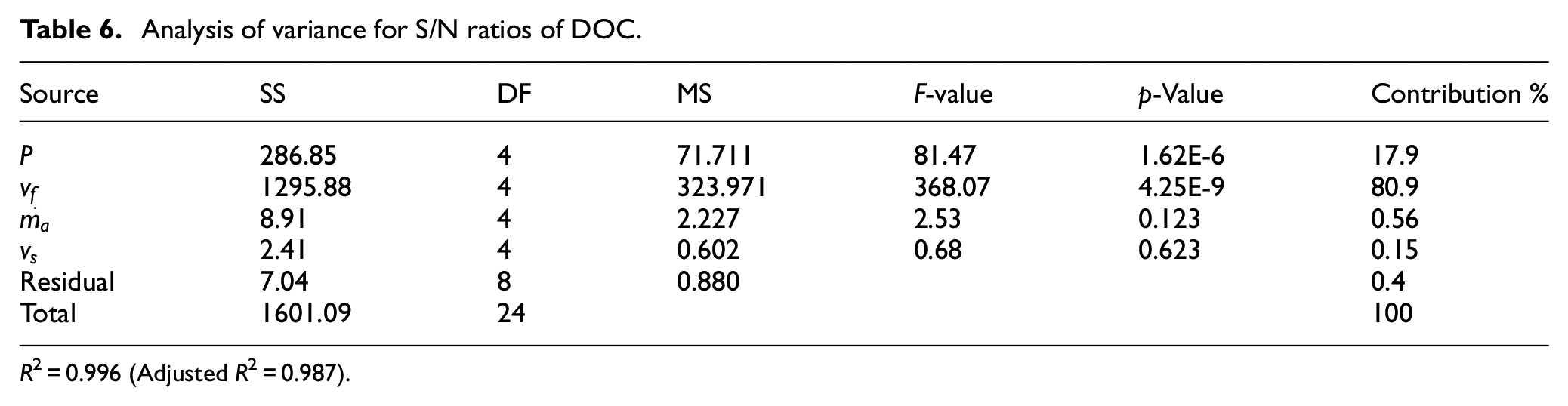
R2 = 0.996 (Adjusted R2 = 0.987).
Analysis of the signal-to-noise (S/N) ratio was conducted using the larger the better criterion. Figure 14 reveals that the S/N ratio of DOC decreases upon increasing traverse rate while it increases by increasing waterjet pressure. On contrary, the S/N ratio is neutrally affected by abrasive mass flow rate and workpiece speed. From the given figure, the optimal parameter combination that yields the maximum DOC value can be found at p = 450 MPa, vf = 0.1 mm/s, ma = 9.45 g/s, and vs = 1.43 m/s; accordingly, the optimum DOC can be estimated as 4.375 mm.
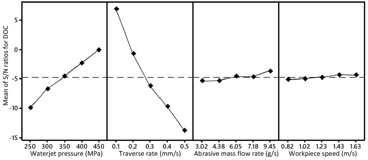
Main effect plot for S/N ratios of DOC (Larger is better).
Figure 15 presents the interactions among the process parameters affecting the output DOC. A significant interaction effect is found between each of these factors: waterjet pressure and abrasive mass flow rate, traverse rate and workpiece speed, and abrasive mass flow rate and workpiece speed. Less interaction is observed among the other parameter combinations.
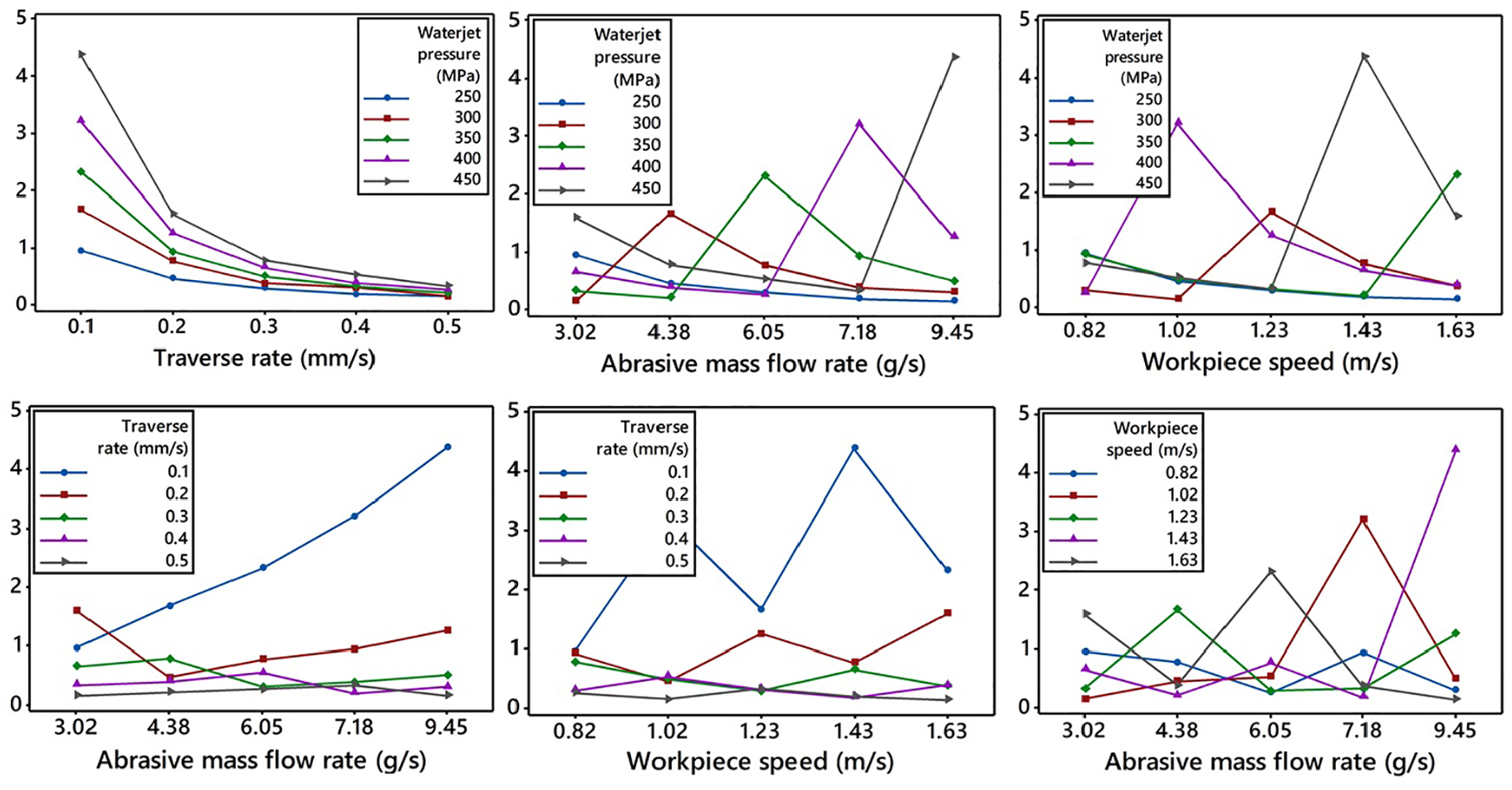
Interaction plots of process parameters for DOC.
Conclusion
In the present study, a user-friendly FE model was developed to simulate the radial mode AWJT of AISI 4140 steel. Four variable AWJT parameters were considered in this model, including waterjet pressure, traverse rate, abrasive mass flow rate and workpiece speed. Two methodologies were proposed to inclusively investigate the erosion rate under different turning conditions. The simulated crater profile was utilized to obtain the numerical DOC and a comparison was made between the FE and experimental results. The following conclusions can be drawn as follows:
According to the observation of erosion rate with simulation time progression, the single-impact or limited multiple-impact models cannot competently express the erosion process under AWJ machining conditions.
Less deformed craters by percentages of 9.3% and 7%, respectively, were obtained when increasing the waterjet pressure and abrasive mass flow rate to their highest levels. Higher deformed craters by a percentage of 2.2% were produced when doubling the workpiece speed. The influence of the traverse rate on deformation was negligible.
The developed methodology of determining the DOC showed a good agreement between the FE and experimental results with a mean absolute error of 9.74% while using different pressures (250–450 MPa), traverse rates (0.1–0.5 mm/s), abrasive mass flow rates (3.02–9.45 g/s), and workpiece speeds (0.82–1.63 m/s).
The application of Python scripting feature saves a lot of time spent in modeling, editing, and testing the model where the whole modeling process no longer takes more than few seconds to complete.
The most significant factors affecting the experimental DOC are the traverse rate and waterjet pressure with less significance for abrasive mass flow rate and workpiece speed, respectively.
Using Taguchi’s approach, the optimum parameter combination for maximum DOC was obtained at waterjet pressure of 450 MPa, traverse rate of 0.1 mm/s, abrasive mass flow rate of 9.45 g/s, and workpiece speed of 1.43 m/s.
The proposed FE model proved its ability to mimic the erosion process in the radial mode AWJT under a wide range of process factors. This model may be integrated with CAM software to produce near-net-shape parts by employing the radial mode as a rough turning process. The future modifications of this model may also include the effect of SOD on the kinetic energy and spreading of the abrasive particles. Further, the influence of abrasive recycling may be considered after analyzing the new sizes, shapes, and distributions of the abrasive particles used. Different materials should be integrated and tested with the current model, especially hard to cut materials.
Footnotes
Acknowledgements
The author(s) would like to thank Cladex Industries Co., El Obour City, Egypt, for providing technical support and assistance while performing the machining experiments.
Declaration of conflicting interests
The author(s) declared no potential conflicts of interest with respect to the research, authorship, and/or publication of this article.
Funding
The author(s) received no financial support for the research, authorship, and/or publication of this article.